
Index 226
Chip-composed Sequence Timer Circuit
Published:2011/5/9 9:27:00 Author:Joyce | Keyword: Chip-composed, Sequence, Timer
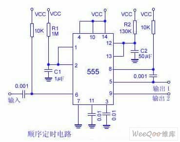
The 0.001 μF coupling capacitance will send the output of first half of the 556 double timer to the second half part and give the total delay equalling the sum of each individual delay . To connect foot 6 to the ground can start the first half of the timer. After 1.1 R1C1 has set the time interval, the second timer begins to delay, and the value isdecided by1.1R2C2. (View)
View full Circuit Diagram | Comments | Reading(700)
Weak Current Basic Amplification Circuit composed of CA3140
Published:2011/5/9 9:31:00 Author:Joyce | Keyword: Weak Current, Basic Amplification, composed of CA3140

Weak Current Basic Amplification Circuit composed of CA3140 (View)
View full Circuit Diagram | Comments | Reading(1396)
A/D Converter Output Interface Circuit Composed of uA741
Published:2011/5/9 9:33:00 Author:Joyce | Keyword: A/D, Converter, Output, Interface, Composed of uA741
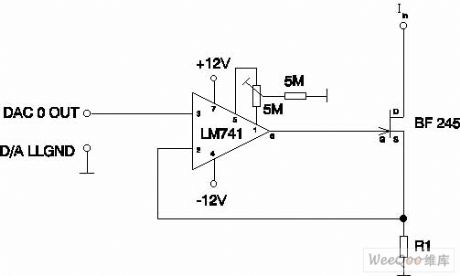
A/D Converter Output Interface Circuit Composed of uA741
(View)
View full Circuit Diagram | Comments | Reading(2748)
C1010 quartz monolithic integrated circuit diagram
Published:2011/5/9 2:28:00 Author: | Keyword: quartz monolithic
C1010 is a piece of quartz monolithic integrated circuit.It's widely used in various brands of quartz clock circuit, such as Polaris, rose film series.
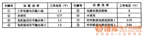
1. pin functions and data
C1010 integrated circuit uses 8-pin dual small package.The pin functions and data are listed in Table 1.
Table 1 C1010 integrated circuit's pin functions and data
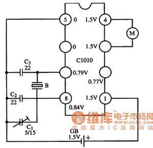
2.Typical application circuit
The typical application circuit of quartz's control circuit which is composedof C1010 integrated circuit is shown in Figure 1.
Figure 1 typical application circuit of C1010 integrated circuit
(View)
View full Circuit Diagram | Comments | Reading(2038)
The PC Intergrated Circuit of BDT306 Communication Single Sheet
Published:2011/5/9 21:51:00 Author:Borg | Keyword: Intergrated, BDT306, Communication Single Sheet
BDT306 is a kind of PC intergrated circuit of communication single sheet used in caller ID display phones.
1. Function Features
BDT306 intergrated circuits contain the generators of dialing pulse and two-tone dialing, LCD display drive circuit, the Codec circuit of key-matrix send-in signals, caller ID display decode circuit, hand-free control phones, tone drive circuit and mute control circuit. It can not only control the reception, treatment and display of caller data,but also be the pulse/two-tone dialing circuit, perpetual calendar circuit and other control circuit, fullfilling multiple functions of the phone itself.
2. Pin Functions and relevent data
BDT306 intergrated circuit encapsulated in 74 Pinning, and the lead pin and date of the circuit are as shown in the following tables.
Table 1 the pinning functions and data of BDT306 intergrated circuit (View)
View full Circuit Diagram | Comments | Reading(571)
Electric Heaters Like Electric Iron Current-limiting Thermostatic Circuit
Published:2011/5/7 2:16:00 Author:Joyce | Keyword: Electric Heaters, Like Electric Iron, Current-limiting, Thermostatic
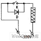
Some electric heaters in daily use likeelectric iron would not only waste a large amount of electric energy ,but burn out electrothermal cores because of long time operation. If we connect a diode to the electric circuit, the current will be limited by the power,which is supplied by the diode half-wave rectification when the electric appliance pauses to operate. In this way,the voltage of the electric appliance would decrease by 50%,and the electric appliance would keep in a preheated state. Once the K in the graph is closed when in use, the electric appliance will function properly with a full load input. The connection of components is shown in the graph.
Electric Heaters Like Electric Iron Current-limiting Thermostatic Circuit (View)
View full Circuit Diagram | Comments | Reading(955)
Low-voltage Automatic Switching Circuit
Published:2011/5/7 3:02:00 Author:Joyce | Keyword: Low-voltage, Automatic, Switching
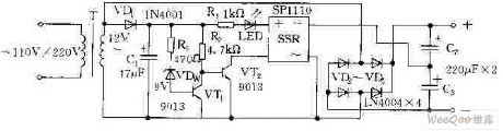
Low-voltage Automatic Switching Circuit is shown in the graph below.When the electric supply of 220V is depressurized by transformer T, VDw will breakdown thus making VT1 breakover and VT2 cut off.Meanwhile,the solid-state relay SSR will shutoff.At this time, after being bridge rectified by VD2 ~ VD5 andfiltered by C2.C3,it will output about 14V dc voltage. When the input ac voltage is 110V, after being depressurized by T, it is insufficient to breakdown VDw,so VT2 will breakover and VT1 will cutoff and SSR will be connected. At this moment, SSR, VD2 ~ VD3 and C2 、C3 will constitute a voltage doubling circuit ,which still output about 14V dc voltage. And the LED indicator light will be on.
(View)
View full Circuit Diagram | Comments | Reading(720)
Relay-composed Start-up Circuit
Published:2011/5/7 3:23:00 Author:Joyce | Keyword: Relay-composed, Start-up
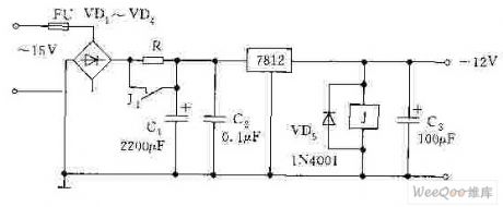
Relay-composed Start-up Circuit is shown in the graph below. In the input end of the power ,resistance R is connected.R has two functions.the first oneis that it can prevent impluse current on the large capacitance C1 in starting up,which wouldimpact the poweritself;the second one is to prolong the time when the load is receiving the electric supply. In this process, because the voltage of the relay J in the output end is less than 12 V ,the actuation voltage, R will be connected to the circuit to limit the current and depressurize the voltage.As the charging of C1, C3 completes, relay J contacts and actuates to short-circuit R. At this moment, power supply will function properly.
(View)
View full Circuit Diagram | Comments | Reading(559)
QS5K2 Internal Circuit
Published:2011/5/9 21:40:00 Author:Sharon | Keyword: Internal
QS5K2 Internal Circuit is shown below:
(View)
View full Circuit Diagram | Comments | Reading(565)
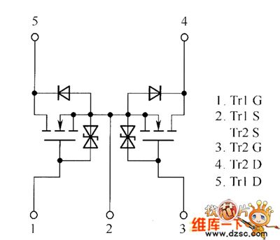
QS5U12,QS5U13 Internal Circuit
Published:2011/5/9 21:30:00 Author:Sharon | Keyword: Internal
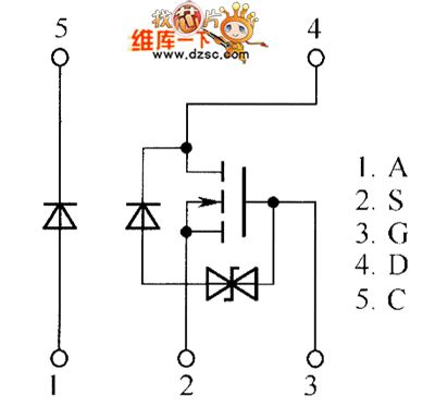
QS5U12,QS5U13 Internal Circuit is shown below:
(View)
View full Circuit Diagram | Comments | Reading(501)
TDA7269-AB class of two-channel audio power amplifier integrated circuit diagram
Published:2011/5/6 4:52:00 Author:Ecco | Keyword: AB class , two-channel , audio, power amplifier , integrated circuit
TDA7269 is the AB class two-channel audio power amplifier integrated circuit produced by Philips, it is widely used in Changhong, TCL, and other rear projection large-screen color TV. 1. Features of functionTDA7269 IC is mainly composed of two power amplifier circuits with the same functions, mute / standby control circuit, overheat protection and short circuit protection circuit. When Vcc = ± 14V, RL = 80Ω, the output power per channel is typically 10W. 2. Pin functions and data TDA7269 integrated circuit is packaged with 11-pin in a single row, the pin functions and data are listed in Table 1. Table 1 shows TDA7269 integrated circuit pin functions and data.
(View)
View full Circuit Diagram | Comments | Reading(2267)
Unit voltage gain power amplitude modulation device circuit diagram
Published:2011/5/9 4:33:00 Author:Rebekka | Keyword: Unit voltage gain , power amplitude modulation device
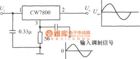
Unit voltage gain power amplitude modulation device circuit diagram.
(View)
View full Circuit Diagram | Comments | Reading(628)
The D.C Amplifier Circuit by Using Switches and Charging Capacitors
Published:2011/5/8 23:50:00 Author:Borg | Keyword: D.C Amplifier Circuit, Switches, Charging Capacitors
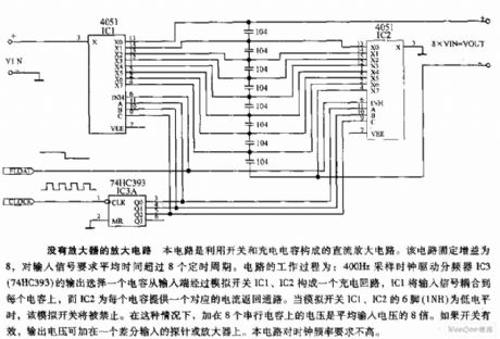
An Amplifier Circuit without any Amplifier:As shown is the amplification circuit without any amplifiers.Thisis a series amplifier circuit formed by switches and charging capacitors,which has a steady power of 8 and requires 8 fixed periods as an average time of input signal. The process ofthe circuit is that a sample clock drived devider IC3(74HC393) of 400Hz output to choose a capacitor to cross the analog switches IC1 and IC2 forming a charging circuit, and then IC2 will couple the input signals to each capacitor, while IC2 is to provide a corresponding current for every capaticor to come back to the circuit. When six contacts of IC1 and IC2 (1NH)are under low electric levels, these analog switches will be turned off. Under this condition, the total voltage on the 8 series capatitors is 8 times ashighasaverage input voltage. If the switches are effective, the output voltage can be put on aprobeor amplifierof difference input. Moreover,this circuit has a lowrequirement on the frequecy of the clock. (View)
View full Circuit Diagram | Comments | Reading(600)
The Amplifier Circuit of Adjustable Gain by Using Digipots
Published:2011/5/8 23:38:00 Author:Borg | Keyword: Amplifier Circuit, Adjustable Gain, Digipot
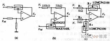
By using the dual digital potentiometer, the amplifer circuit of adjustable gain can be designed as follows(R2 means singal digital POT,and R4 means the consistent resistence), so the resistences of the intergrated operational non-inverting and inverting points always remain the same, therefore , not only the CMRR can be kept quite high, but also the temperature-excursion is hold back.
(View)
View full Circuit Diagram | Comments | Reading(798)
M5218AP-operational amplifier integrated circuit diagram
Published:2011/5/9 1:10:00 Author:Nicole | Keyword: operational amplifier
M5218AP is a common operational amplifier integrated circuit which is produced by Mitsubishi Corp, it is widely used in large screen and other screen color television, audio system, computer and its diaplay and all kinds of electric appliances electronic control circuit.
1. functions and features
M5218AP integrated circuit contains two ways operational amplifier with same functions.
2. pin function and data
M5218AP integrated circuit adopts 8-foot dual in-line package, it is applied to ChangHong CN一15 movement color television, the pin function and data of this integrated circuit is shown in the table1.
(View)
View full Circuit Diagram | Comments | Reading(711)
KA2209-dual track power amplifier integrated circuit diagram
Published:2011/5/6 8:06:00 Author:Nicole | Keyword: dual track, power amplifier
KA2209 is a dual track power amplifier integrated circuit which is produced by South Korea's Samsung, it is widely used in all kinds of low voltage walkman, repeater, multimedia audio, mini speaker and other sound equipments.
1, functions and features
KA2209 integrated circuit contains two-way same function audio frequency power pre-amplifier, audio frequency power amplifier circuit and some other assistant function circuits.
2, pin function and data
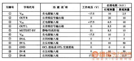
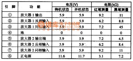
KA2209 integrated circuit adopts 8-foot dual in-line package, the pin function and data of this integrated circuit is shown in the table 1-1.
Indication: Whether the ①, ② foot voltage of KA2209 is 1/2 of VCC or not, it is an important basis to decide whether IC is normal.
(View)
View full Circuit Diagram | Comments | Reading(1098)
KA2206B-2W stereo audio power amplifier integrated circuit diagram
Published:2011/5/6 8:52:00 Author:Nicole | Keyword: stereo, audio, power amplifier
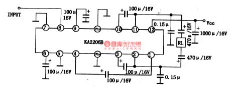
KA2206B is a 2W stereo audio power amplifier integrated circuit which is produced by South Korea's Samsung, it is widely used in home audio, computer audio, car audio and some devices.
1, functions and features
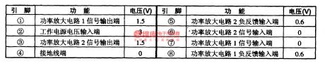
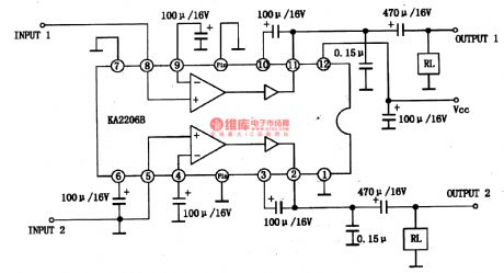
KA2206B integrated circuit contains two gain changeable preamplifiers and two power amplifiers. The input impedance is 25K, it can adjust the gain of amplifier by adjusting the capacity of ④, ⑨ foot external capacitance. The range of power voltage is 9-15V. When the power voltage are 12V, RL=4、THD=l0%, the output power of each audio channel is 2.3W. The typical application circuit of integrated block used in dual sound is shown in the figure 1-1. The typical application circuit of KA2206B integrated block used in BTL mode is shown in the figure 1-2. Then the output power is 4.7W.
The figure 1-1 is the typical application circuit of KA2206B integrated block used in dual sound
The figure 1-2 is the typical application circuit of KA2206B integrated block used in BTL mode (View)
View full Circuit Diagram | Comments | Reading(28378)
Capacitance-used Soft Start Circuit
Published:2011/5/7 3:54:00 Author:Joyce | Keyword: Capacitance-used, Soft Start
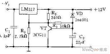
The following graph is the capacitance-used soft start circuit.At the sudden moment when C2 is supplied with power, VTwill be offset by R2, R3 and become power on, resulting in short circuit of R1, which equalsthat the adjustment end of LM317 is connected to the ground. The power output is 1.25 V, and with the charge of C2 going on, the output voltage will rise gradually.According to the component parameters in the graph, it takes 3s for it to reach the rated output voltage.The function of VD is to discharge the electricity of C2 after the power supply is cut off,so as to guarantee the proper soft start next time.
(View)
View full Circuit Diagram | Comments | Reading(1628)
Basic Instrument Amplifier Circuit
Published:2011/5/6 11:11:00 Author:Joyce | Keyword: Basic, Instrument, Amplifier
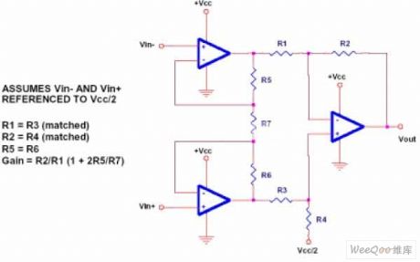
Basic Instrument Amplifier Circuit (View)
View full Circuit Diagram | Comments | Reading(703)
CA3140-composed Broadband Output Amplification Circuit
Published:2011/5/6 11:18:00 Author:Joyce | Keyword: CA3140-composed, Broadband, Output, Amplification
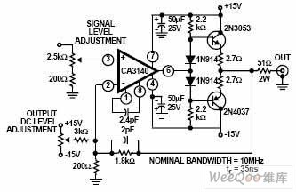
CA3140-composed Broadband Output Amplification Circuit (View)
View full Circuit Diagram | Comments | Reading(3686)
| Pages:226/250 At 20221222223224225226227228229230231232233234235236237238239240Under 20 |
Circuit Categories
power supply circuit
Amplifier Circuit
Basic Circuit
LED and Light Circuit
Sensor Circuit
Signal Processing
Electrical Equipment Circuit
Control Circuit
Remote Control Circuit
A/D-D/A Converter Circuit
Audio Circuit
Measuring and Test Circuit
Communication Circuit
Computer-Related Circuit
555 Circuit
Automotive Circuit
Repairing Circuit