
Index 230
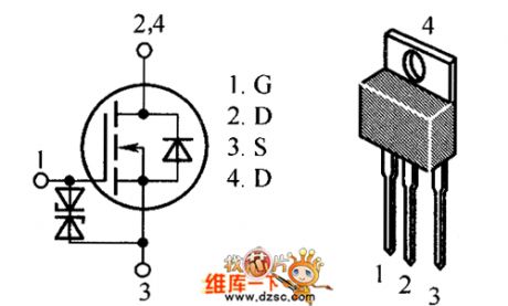
AP2315GEN Internal Circuit
Published:2011/5/6 0:45:00 Author:Felicity | Keyword: Internal Circuit,
The picture above shows the AP2315GEN internal circuit. (View)
View full Circuit Diagram | Comments | Reading(437)
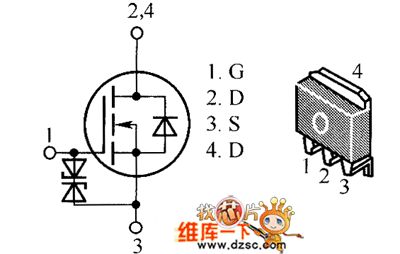
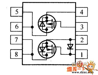
AP1332EU、AP1332GEU、AP2308GEN、AP2318GEN Internal Circuit
Published:2011/5/6 0:48:00 Author:Felicity | Keyword: Internal Circuit,
The picture above shows the AP1332EU、AP1332GEU、AP2308GEN、AP2318GEN internal circuit. (View)
View full Circuit Diagram | Comments | Reading(464)
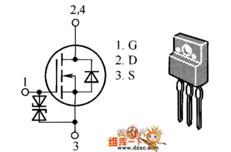
AOP610 Internal Circuit
Published:2011/5/6 0:50:00 Author:Felicity | Keyword: Internal Circuit,
The picture above show the AOP610 internal circuit. (View)
View full Circuit Diagram | Comments | Reading(660)
Wide Dynamic Range Gain Control Amplifier Circuit
Published:2011/5/5 23:56:00 Author:Joyce | Keyword: Wide, Dynamic Range, Gain, Control, Amplifier
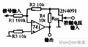
Wide Dynamic Range Gain Control Amplifier Circuit is shown in the graph below.Experience has proved that when using FET as variable resistor to control the amplifier's gain, if the input signal is 1% of the pinch-off voltage, there will be 1% distortion . And in the feedback circuit, if one uses two resistances and a field-effect tube to constitute a T network, the signals could be added to the field-effect tube after being reduced by R1, R2. Therefore it is able to control sizable signals. (View)
View full Circuit Diagram | Comments | Reading(534)
Gain Program-controlled Instrument Amplifier Circuit
Published:2011/5/6 0:04:00 Author:Joyce | Keyword: Gain, Program-controlled Instrument, Amplifier
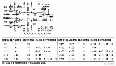
Gain Program-controlled Instrument Amplifier Circuit is shown in the graph below.The circuit uses LH0044 operational amplifer.Connecting it according to the table, one can get different gains (1 ~ 995). Offset voltage has been set below 25μV ,and thetypical bias current is 10μA.
(View)
View full Circuit Diagram | Comments | Reading(652)
Gain Adjustable Test Equipment Isolation Amplifier Circuit
Published:2011/5/6 0:14:00 Author:Joyce | Keyword: Gain, Adjustable, Test Equipment, Isolation Amplifier

Gain Adjustable Test Equipment Isolation Amplifier Circuit is shown in the graph below.With optical coupling isolation amplifier ISO100, one can form a gain test equipment isolation amplifier.The gain of the circuit ranges from 10 to 1000 . The input signal needs to be negative value. The input and output stage of ISO100 is supplied by two groups of ± 15V power supply respectively.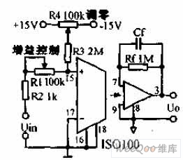 (View)
View full Circuit Diagram | Comments | Reading(702)
Camera Photometric System Circuit
Published:2011/5/6 0:28:00 Author:Joyce | Keyword: Camera Photometric System Circuit
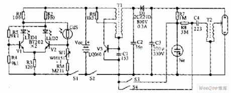
The camera photometric system is composed of two transistors. When the luminance of the subject to be shot is weak, the value of the cadmium sulphide photoconductive resistance will increase,then LED2 will not flash due to cutoff of V2. At this time V1 will breakover,and LED1 will shine. When the luminance of the subject to be shot increases, the resistance of CdS will decrease, and then LED2 will go out,and LED2 will give out light. In this way, it points out whether the flashlight is being used or not.
(View)
View full Circuit Diagram | Comments | Reading(545)
Using NE555 Skillfully as Audio Power Amplifier Circuit
Published:2011/5/5 2:57:00 Author:Joyce | Keyword: Using NE555 Skillfully as, Audio Power, Amplifier

Using NE555 Skillfully as Audio Power Amplifier Circuit (View)
View full Circuit Diagram | Comments | Reading(3041)
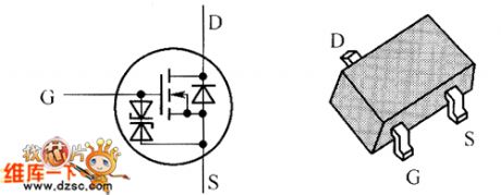
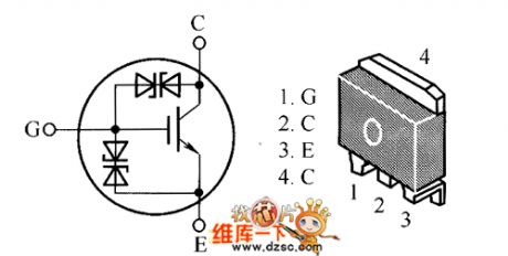
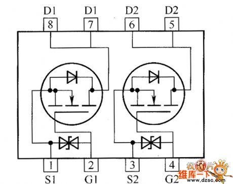
MLP1N06CLT4、MLP1N06CLT4G、MLP2N06CL、MLP2N06CLG Internal Circuit
Published:2011/5/5 9:50:00 Author:Felicity | Keyword: Internal Circuit
The picture above shows the MLP1N06CLT4、MLP1N06CLT4G、MLP2N06CL、MLP2N06CLG Internal Circuit. (View)
View full Circuit Diagram | Comments | Reading(533)
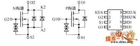
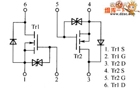
HAT2196C、HAT2202C、HAT2201C、HAT2205C Internal Circuit
Published:2011/5/5 9:53:00 Author:Felicity | Keyword: Internal Circuit,
The picture above shows the HAT2196C、HAT2202C、HAT2201C、HAT2205C Internal Circuit. (View)
View full Circuit Diagram | Comments | Reading(413)
Programmable gain amplifier circuit composed of the AD7523
Published:2011/5/5 19:21:00 Author:TaoXi | Keyword: Programmable, gain amplifier
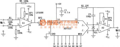
The programmable gain amplifier circuit can amplifies, transforms and filter the analog signal, and interconnects the multiple function-modules of the device, and reconstructs the circuit, also it can adjust the circuit's gain, bandwidth, and threshold.
The programmable gain amplifier circuit composed of the AD7523 is as shown in the figure. The circuit's gain is controlled by the 8-bit data to ensure the gain is between 1 to 256, as from the D7 (MSB) there is only one high-level voltage, so it is able to make 6dB as the step length, from 6dB to 42 dB. The AD7523 has the analog switch and R-2R ladder network, the rated resistance is 5~20kΩ, the center value is 10kΩ. If you input the signal from RFB port, the side input resistance will be low, so we connect the buffer amplifier Al before the RFB port as the inverter. If you input from the Al's same-phase port, you can get the same-phase signal. For the variable gain amplifier, if the gain is high, the imbalance voltage is high, so you need to adjust the Op amp to zero and particular pay attention to the output of Al. We usually do the gain calibration on the RFB port series potentiometer RP2. The set gain of op amp A2 is higher, the closed-loop frequency response is worser because the negative feedback of op amp A2 can be changed. We need to use the op amp with narrow gain variable range or good open-loop frequency feature. For small power or accurate op amp, the AC characteristics are sacrificed, so we should pay more attention when we input the signal of thousands Hz. (View)
View full Circuit Diagram | Comments | Reading(1730)
audio frequency AGC amplification circuit
Published:2011/5/5 18:55:00 Author:TaoXi | Keyword: audio frequency, AGC, amplification
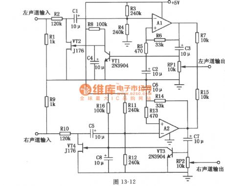
The audio frequency AGC can track and keep watch over the preamplifier's output audio signal voltage level, when the input signal increases, the AGC circuit automatically reduces the gain of the amplifier; when the output signal reduces, the AGC circuit automatically increases the gain of the amplifier to keep the best level of the signal which is got into the A/D, and also it minimizes the reduction wave. The audio frequency AGC amplification circuit is as shown in the figure, this kind of amplifier's dynamic range is greater than 50dB, the output distortion is very small, and it has some points of advantages such as starts fast, decay slowly. You can adjust the voltage level of the circuit input 40~20mV and output 0~1.2V, it has the single power supplier, and the current consumption is less than 1mA(5V voltage). VT2 and VT4 are the P-channel JEFT, it constitutes the equivalent resistor divider with R2, R3, R4 (R10, R11, R12), also it accesses to the input circuit. When the input voltage level is less than 40mV (peak-peak), the input voltage assigns between R2 and R3,R4 equally. A1's output amplitude is not enough to conduct the positive peak detector VT2.
(View)
View full Circuit Diagram | Comments | Reading(2754)
AN7112 power amplifier integrated circuit diagram
Published:2011/5/5 4:18:00 Author:Nicole | Keyword: power amplifier
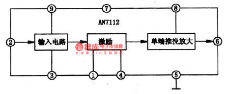
AN7112 is a audio power amplifier integrated circuit which is produced by Panasonic, it is used in 3-5.5 inch miniature TV and computer audio system.
1, internal circuit block diagram
AN7112 integrated circuit contains singal input, audio motivation single-ended pull-push amplifier circuit, the integrated block internal circuit block diagram is shown as the figure1.
Figure1 is the AN7112 integrated block's internal circuit block diagram
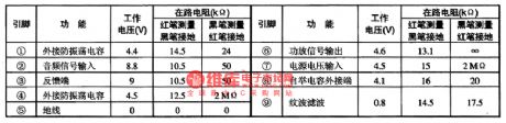
2, pin function and data
AN7112 integrated circuit adopts one line ⑨ foot package, the integrated circuit's pin function and data is shown in the excel 1.
Excel 1 is the AN7112 integrated circuit's 5 foot function and data. (View)
View full Circuit Diagram | Comments | Reading(1103)
FS20VS-6A Internal Circuit
Published:2011/5/5 10:03:00 Author:Felicity | Keyword: Internal Circuit,
The picture above shows the FS20VS-6A Internal Circuit. (View)
View full Circuit Diagram | Comments | Reading(513)
GN4014ZB4LD Internal Circuit
Published:2011/5/5 10:01:00 Author:Felicity | Keyword: Internal Circuit,
The picture above shows the GN4014ZB4LD Internal Circuit. (View)
View full Circuit Diagram | Comments | Reading(485)
FS20KM-6A Internal Circuit
Published:2011/5/5 10:04:00 Author:Felicity | Keyword: Internal Circuit
The picture above shows the FS20KM-6A Internal Circuit. (View)
View full Circuit Diagram | Comments | Reading(696)
FS100VSJ-03F Internal Circuit
Published:2011/5/5 10:05:00 Author:Felicity | Keyword: Internal Circuit
The picture above shows the FS100VSJ-03F Internal Circuit. (View)
View full Circuit Diagram | Comments | Reading(527)
FDR8521L Internal Circuit
Published:2011/5/5 10:07:00 Author:Felicity | Keyword: Internal Circuit
The picture above shows the FDR8521L Internal Circuit. (View)
View full Circuit Diagram | Comments | Reading(490)
CEM8207、CEM8208 Internal Circuit
Published:2011/5/5 10:10:00 Author:Felicity | Keyword: Internal Circuit
The picture above shows the CEM8207、CEM8208 Internal Circuit. (View)
View full Circuit Diagram | Comments | Reading(426)
EM6K1 Internal Circuit
Published:2011/5/5 10:08:00 Author:Felicity | Keyword: Internal Circuit
The picture above shows the EM6K1 Internal Circuit. (View)
View full Circuit Diagram | Comments | Reading(782)
| Pages:230/250 At 20221222223224225226227228229230231232233234235236237238239240Under 20 |
Circuit Categories
power supply circuit
Amplifier Circuit
Basic Circuit
LED and Light Circuit
Sensor Circuit
Signal Processing
Electrical Equipment Circuit
Control Circuit
Remote Control Circuit
A/D-D/A Converter Circuit
Audio Circuit
Measuring and Test Circuit
Communication Circuit
Computer-Related Circuit
555 Circuit
Automotive Circuit
Repairing Circuit