
Automotive Circuit
Index 7
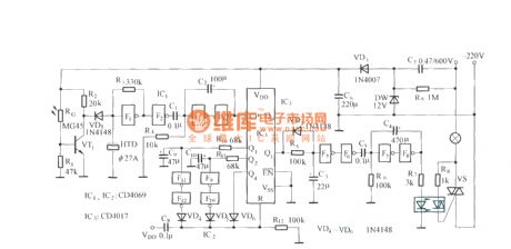
Anti-interference energy-saving switch circuit diagram
Published:2011/9/26 1:45:00 Author:Rebekka | Keyword: Anti-interference , energy-saving switch
View full Circuit Diagram | Comments | Reading(994)
Pulse dialing nine-way infrared remote control circuit diagram (LR40992, μPC1373)
Published:2011/9/26 2:20:00 Author:Rebekka | Keyword: Pulse dialing, nine-way infrared remote control
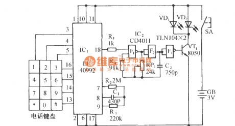
Transmitter circuit:
Receiver circuit:
(View)
View full Circuit Diagram | Comments | Reading(1408)
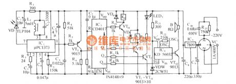
Human body thermoelectric automatic energy-saving lamps circuit diagram
Published:2011/9/26 2:10:00 Author:Rebekka | Keyword: energy-saving lamps
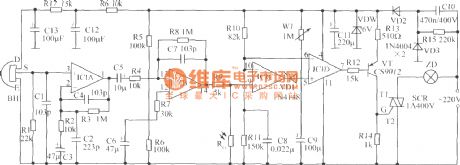
IC1 is four operational amplifiers LM324. Sensor BH is RS03. If you use some other types of sensors, it should have the right design of the amplifier gain support, but it must select two-component type. (View)
View full Circuit Diagram | Comments | Reading(1666)
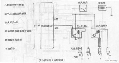
Hafei Simbo car engine ignition system circuit diagram
Published:2011/9/15 22:56:00 Author:Rebekka | Keyword: Hafei Simbo car, engine ignition system
View full Circuit Diagram | Comments | Reading(1391)
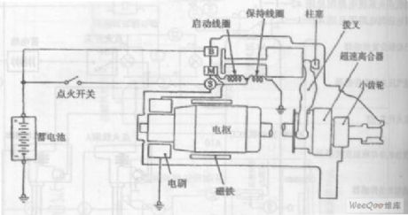
Hafei Simbo car start system circuit diagram
Published:2011/9/15 22:55:00 Author:Rebekka | Keyword: Hafei Simbo , car start system
View full Circuit Diagram | Comments | Reading(1148)
Chang an Alto car air conditioning system circuit diagram
Published:2011/10/18 2:54:00 Author:Rebekka | Keyword: Chang an Alto car, air conditioning system
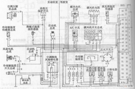
Chang'an Alto car air conditioning system circuit diagram is shown as above. (View)
View full Circuit Diagram | Comments | Reading(2860)
Chang an Alto car fuse and relay circuit diagram
Published:2011/10/18 2:54:00 Author:Rebekka | Keyword: Chang an Alto car , fuse and relay
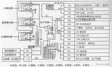
R-red, W-white, C-green, Y-yellow, U-blue, B-black, N-brown, S-gray, R-purple.
Chang'an Alto car fuse and relay circuit diagram is shown as above. (View)
View full Circuit Diagram | Comments | Reading(1354)
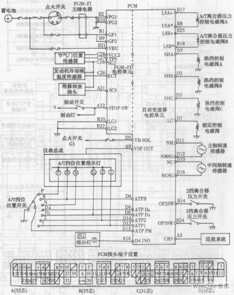
Accord automatic transmission PMC connector pin location and schematic
Published:2011/9/13 2:58:00 Author:Rebekka | Keyword: Accord automatic transmission, PMC connector pin location
View full Circuit Diagram | Comments | Reading(686)
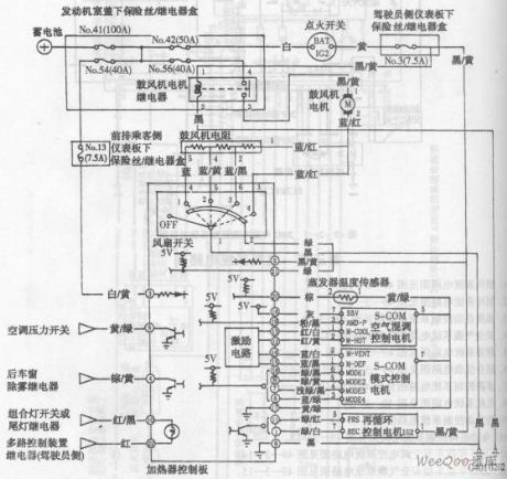
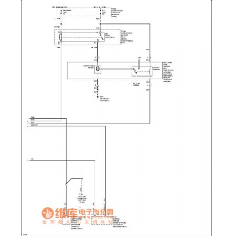
Accord sedan heating system circuit diagram
Published:2011/9/15 22:49:00 Author:Rebekka | Keyword: Accord sedan, heating system
View full Circuit Diagram | Comments | Reading(534)
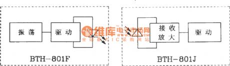
Transmitter and receiver circuit composed of BTH-801F/801J infrared remote control transmitter and receiver module
Published:2011/9/26 1:44:00 Author:Rebekka | Keyword: Receiver module, infrared remote control transmitter , transmitter and receiver
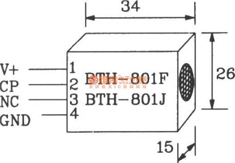
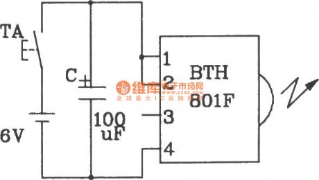
BTH-801F/BTH-80J is a dedicated module for new infrared remote control transmitter and receiver. It is suitable for infrared remote control switch and alarm ect.
BTH-801F/BTH-80lJ shape pinout.
Main electrical parameters of BTH-801F/801J infrared remote control transmitter and receiver module is shown as below. Power supply voltage 4~8V; Receiver module is less than 3mA; Operating frequency is adjustable between 40kHz to 3060kHz; Operating temperature 18~+60℃, storage temperature 25~+90℃; Distance 5~lOm; Mode of action is direct, reflecting both.
Composed of BIH-801F single infrared remote control transmitter circuit.
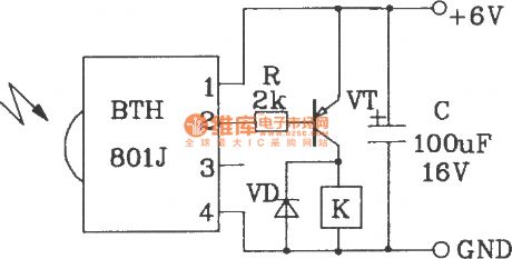
Composed of BTH-801J single infrared remote control transmitter circuit.
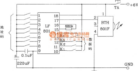
Composed of BTH-801F multi-channel infrared remote control transmitter circuit.
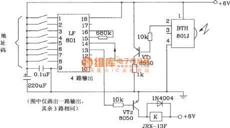
Composed of BTH-801J multi-channel infrared remote control transmitter circuit.
(View)
View full Circuit Diagram | Comments | Reading(1791)
Toyota Land Cruiser 70 light off-road vehicle interior lights and signal principle circuit diagram
Published:2011/9/13 2:45:00 Author:Rebekka | Keyword: Toyota Land Cruiser 70 , light off-road vehicle
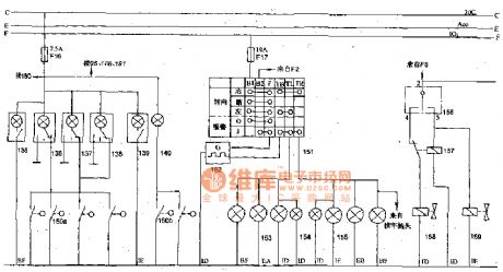
135,139- crew lights(movable vehicle roof in moon shape); 136,137,138- front interior lights; 140-gate controlledlight; 150a, 150b- door control switches; 151-turning and hazard warning switch; 152-turning flasher; 153-left turn signals; 154-turning indicator; 155 right-turn signal; 156-transfer case controlingrelay switch; 157-sub-actuator control relay; 158-transfer case controlingl solenoid valve (2WD); 159-transfer case controlling solenoid valve (4WD); 160-differential lock indicator light. (View)
View full Circuit Diagram | Comments | Reading(2039)
Beijing Cherokee BJ2021 light off-road vehicles lighting signal headlamp circuit diagram
Published:2011/9/13 2:26:00 Author:Rebekka | Keyword: Beijing Cherokee , light off-road vehicles
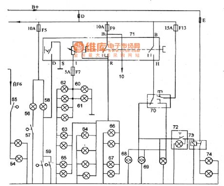
10-buzzer; 54-brake light; 55-brake light switch; 56-glove box lighting; 57-glove box light switch; 58-internal dome lamp; 59-control switch; 60-floor (min drive) lights; 61-air-conditioned light; 62-instrument light; 63-rear width lamp; 64-taillight; 65-frontwidth light; 66-stop light; 67-license plate light; 68-beam light; 69-headlamp; 70-changing light and ultra-light switch; 71-light switch; 72- fog lamp switch; 73-fog lamp relay; 74-fog lamp
(View)
View full Circuit Diagram | Comments | Reading(985)
Multi-control switch circuit diagram 2
Published:2011/9/26 1:56:00 Author:Rebekka | Keyword: Multi-control switch circuit
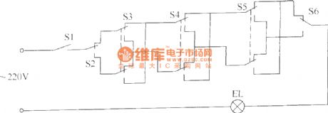
This example describes the multi-control switch. It uses multi-way switch to control one rout light(which may be more bulbs in parallel). It applies to hotels, rooms, corridors and the corridor and other places. The multi-control switch circuit is composed of the control switch S1 ~ S6 EL composition and lighting. The circuit is shown as above.
S1 uses single-pole switch or bipolar switches with contact current capacity in1OA. S2 and S6 usedouble-pole (SPDT) switch. S3 ~ S5 use optional double-pole (DPDT) switch.
(View)
View full Circuit Diagram | Comments | Reading(892)
Multi-control switch circuit diagram 3
Published:2011/9/26 1:59:00 Author:Rebekka | Keyword: Multi-control switch
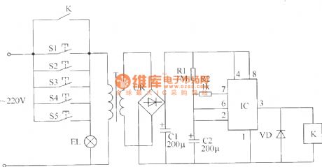
This example describes a multi-place control switch with time delay function,which usesmulti-buttons to control one rout light. Pressing any button can lit the light, the lights will be automatically turn off hin about 3mins. The switch circuit is compose of S1 ~ S5, power circuit and timing control circuit. The circuit is shown as the chart.
Somponent selection.R1 and R2 use 1/4W or 1/8W carbon film resistors. C1 and C2 select aluminum electrolytic capacitors with voltage in 25V. VD uses 1N4001 or 1N4007 type silicon rectifier diodes. IC uses NE555 type time-base integrated circuit.
(View)
View full Circuit Diagram | Comments | Reading(822)
Multi-control switch circuit diagram 4
Published:2011/9/26 2:02:00 Author:Rebekka | Keyword: Multi-control switch circuit
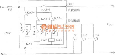
This example describes the multi-place control switch, you can turn on or off any partial load(electrical equipment) of the working power source. The switch can be used for corridor, public areas lighting control. It can also be used for industrial production (more than one place on the factory floor control of a set of production equipment). The multi-place control switch circuit consists of intermediate relays KA1 ~ KA3 and S1 ~ Sn. It is shown as picture.
If you need to control the power of a larger load, you can use AC contactor to replace KA1. Components selection: S1~Sn selects moving together (normally open) buttons. KA1 ~ KA3 select 220V AC relays.
(View)
View full Circuit Diagram | Comments | Reading(845)
Multi-control switch circuit diagram 1
Published:2011/9/26 2:08:00 Author:Rebekka | Keyword: Multi-control switch circuit
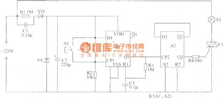
This example describes the multi-place control switch, you can use multi-button switch control one route electrical appliances (eg lights). It applies to hotels, hospitals, corridors, staircases and other more than 3-way switch controlling situation. The circuitis composed ofthe power supply circuit, monostable, bistable trigger, and buttons S1 ~ Sn, thyristor VT etc.Components select.R1 selects 1/2W carbon film resistors or metal film resistors; R2 ~ R4 select 1/4W carbon film resistors. C1 selects polyester capacitor or CBB capacitor with withstand voltage being greater than 400V; C2 uses 25V electrolytic capacitor; C3 uses monolithic capacitors or polyester capacitors. VD selects 1N4007 silicon rectifier diode. VS selects 1/2W, 9V voltage silicon diode. VT selects 3A, 600V bi-directional thyristor. IC selects CD4013 or C043 dual D flip-flop integrated circuits. S1 ~ Sn select normally open buttons.
(View)
View full Circuit Diagram | Comments | Reading(1230)
Cadillac electronic suspension circuit diagram( road-sensing suspension)
Published:2011/8/24 2:23:00 Author:Jessie | Keyword: Cadillac electronic suspension, road-sensing suspension
View full Circuit Diagram | Comments | Reading(811)
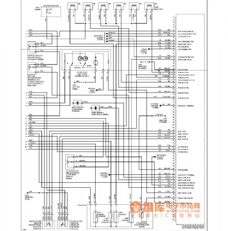
Buick engine performance circuit diagram(3.8l,vink)
Published:2011/8/19 1:10:00 Author:Jessie | Keyword: Buick , engine performance, 3.8l,vink

View full Circuit Diagram | Comments | Reading(876)
Buick engine performance circuit diagram(3.8l,vin1)
Published:2011/8/19 1:07:00 Author:Jessie | Keyword: Buick , engine performance , 3.8l,vin1
View full Circuit Diagram | Comments | Reading(675)
Cadillac wiper washer circuit diagram( with rain sensor)
Published:2011/8/19 2:09:00 Author:Jessie | Keyword: Cadillac , wiper washer, rain sensor
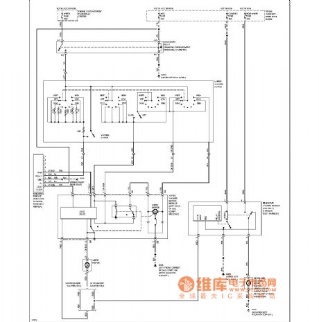
View full Circuit Diagram | Comments | Reading(1224)
| Pages:7/164 1234567891011121314151617181920Under 20 |
Circuit Categories
power supply circuit
Amplifier Circuit
Basic Circuit
LED and Light Circuit
Sensor Circuit
Signal Processing
Electrical Equipment Circuit
Control Circuit
Remote Control Circuit
A/D-D/A Converter Circuit
Audio Circuit
Measuring and Test Circuit
Communication Circuit
Computer-Related Circuit
555 Circuit
Automotive Circuit
Repairing Circuit