
Automotive Circuit
Index 13
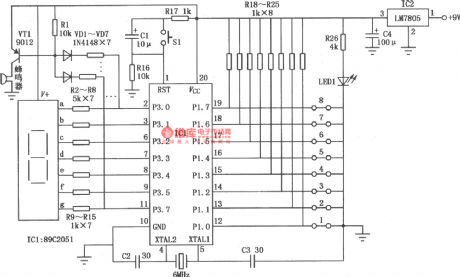
Digital Display Eight-circuit Disconnection Detector Composed of Singlechip 89C2051
Published:2011/9/8 1:53:00 Author:Sue | Keyword: Digital Display, Eight-circuit, Disconnection Detector
View full Circuit Diagram | Comments | Reading(2642)
Inverter Electromagnetic Ticker Timer Composed of CD4017
Published:2011/9/8 1:54:00 Author:Sue | Keyword: Inverter, Electromagnetic Ticker, Timer
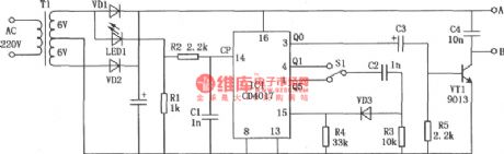
The electromagnetic ticker timer has a simple structure and is very economic. It is one of the most widely used apparatus in middle school physical experiment and teaching. The main disadvantage is that it may have big error in experiment. The reason is that, first, the electromagnetic ticker timer's needle will impede the paper's moving process when it is working, which will make the paper slow down. Secondly, the electromagnetic ticker timer is driven by the alternating current which is voltage-reduced. It tickering period is one period of alternating current, that is 0.02s. (View)
View full Circuit Diagram | Comments | Reading(1756)
Intelligent Simple Pendulum Period Determinator(89C2051,CD40106)
Published:2011/9/8 1:53:00 Author:Sue | Keyword: Intelligent, Simple Pendulum Period, Determinator
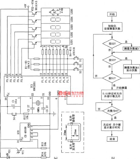
The picture shows the intelligent simple pendulum period determinator. It can be used in the experiment which measures the simple pendulum period. The circuit has high measurement accuracy, which can be as accurate as 1/100s. What's more, it doesn't need counting and timing by hand, so it only needs to set the measure times as several. (View)
View full Circuit Diagram | Comments | Reading(1477)
Rain and Snow Amount Telemetry Circuit
Published:2011/9/8 1:54:00 Author:Sue | Keyword: Telemetry
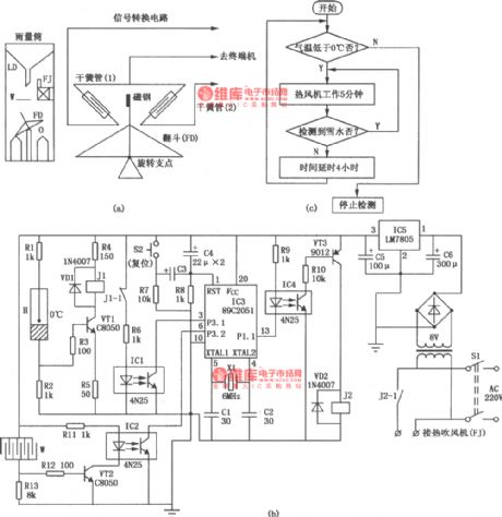
In winter, in order to forecast the water regimen, the measurement of rainfall as well as snowfall is needed. As seen in the circuit, the circuit adds some more components on the old rainfall amount telemetry circuit, and then the new circuit can realise the two functions of measuring rainfall and snowfall amount. When it is raining, the rain flows into the tipping bucket FD through the rain measuring glass's funnel LD in the figure (a). When the tipping bucket on one side has accumulated 1mm rain, the tipping bucket loses balance and will turn over. Then the rain in the tipping bucket will be poured out. At the same time, the tipping bucket on the other side begins to accumulate rainfall. (View)
View full Circuit Diagram | Comments | Reading(958)
Simple Cable Quick Detector(74HC4017)
Published:2011/9/8 1:54:00 Author:Sue | Keyword: Simple Cable, Quick Detector
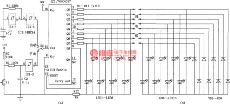
The cable quick detector is mainly used to detect the connection and disconnection states of the computer LAN cable and other similar comprehensive digital network cable and analog cable, which is more convenient and quick than using multimeter. The circuit is divided into two parts---main circuit and remote circuit. Even if the cable's two terminals are not in the same place, it can also detect the circuit. As seen in the figure (a), the main circuit consists of clock generating circuit which is composed of IC1 phase reversal schmitt trigger 74HC14 and LED circuit in proper order which is composed of IC2. The figure (b) shows the remote circuit. (View)
View full Circuit Diagram | Comments | Reading(1460)
Practical Telephone Detector(555,CD4017,CD4518)
Published:2011/9/8 1:33:00 Author:Sue | Keyword: Practical Telephone Detector
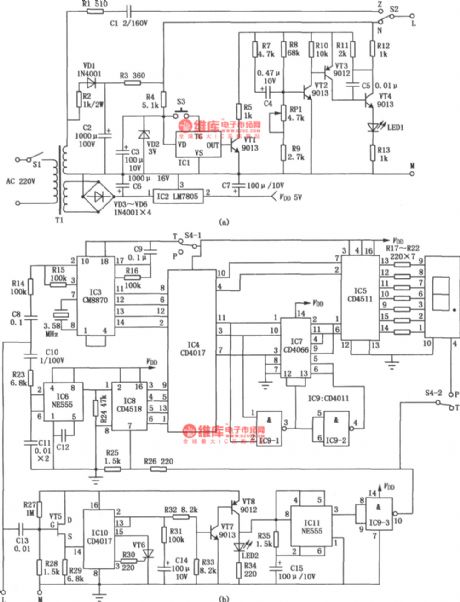
The telephone detector which uses this circuit can accurately identify and remove the fault of the telephone ringing circuit, speaking circuit and dial-up circuit. It is very convenient. The figure (a) shows the power circuit, ringing and speaking detection circuit. The power is provided by 220v ac voltage through the voltage transformer T1 and is output in two groups. One group is 9v ac voltage which will output 5v direct current voltage to work as detection power after it is rectified by diode VD3-VD6, filtrated by capacitor C6,C7, voltage stablized by three-terminal voltage stablizing block IC2. (View)
View full Circuit Diagram | Comments | Reading(1329)
Electronic Sign Board with Acousto-optic Control
Published:2011/9/8 1:55:00 Author:Sue | Keyword: Electronic Sign Board, Acousto-optic Control
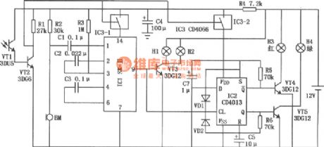
The picture shows the automatic electronic sign board circuit. It mainly consists of acoustic control circuit, oscillating circuit and drive display circuit. (View)
View full Circuit Diagram | Comments | Reading(939)
High Input Impedance Double Wave Linear Detection Circuit with Simple Adjustment(RC4558DN)
Published:2011/9/8 1:55:00 Author:Sue | Keyword: High Input Impedance, Double Wave, Linear Detection, Simple Adjustment
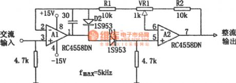
The picture shows the high input impedance double wave linear detection circuit. The circuit doesn't need precision resistance. Its characteristic is that it can simply make up the gain inequality of the positive and negative input by adjusting VR1. As the signal is input from A1's same-phase terminal, the input impedance is high and will have no nolinear distortion. In the positive half period of the input alternating current signal, A1's output is positive, and D1 is positively offset and is connected. So A2's input is also positive, and A2's input is positive too. R2, VR1,R1 will generate negative feedback to A1 with β=1. All in all, they will become a same-phase amplifier with a gain of 1. (View)
View full Circuit Diagram | Comments | Reading(835)
Broadband Linear Detection Circuit with Bandwidth of 10MHz
Published:2011/9/8 1:56:00 Author:Sue | Keyword: Broadband Linear Detection
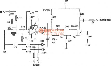
The picture shows the broadband linear detection circuit with bandwidth of 10MHz. The circuit is the broadband linear detection circuit with bandwidth of 10MHz which is used on measuring appratus such as millivoltmeter. The operational amplifier uses the broadband's μPC53, and its output is amplified by differential amplifer which is composed of triode 2SC384. In the circuit, it uses germanium diode as detection-used diode. Then it connects the diode to the negative feedback circuit. The differential circuit raises the power voltage. (View)
View full Circuit Diagram | Comments | Reading(651)
Multiplying Wave Detector Circuit Without Voltage Transformer(MC1596G)
Published:2011/9/8 1:56:00 Author:Sue | Keyword: Multiplying, Wave Detector, Without Voltage Transformer
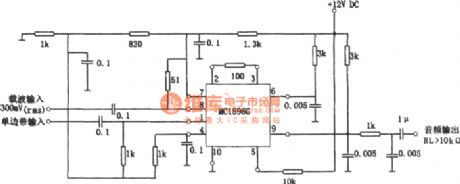
The picture shows the multiplying wave detector circuit without voltage transformer. The multiplying wave detector circuit uses MC1596 instead of LC oscillating circuit and voltage transformer. The circuit can be used in frequency range from low to 100KHz wide band, by changing the parameter of the output RC's low pass filter. The circuit can be used in mixer, frequency multiplier and modulator. (View)
View full Circuit Diagram | Comments | Reading(818)
Multiplying Wave Detector Composed of MC1496
Published:2011/9/8 1:56:00 Author:Sue | Keyword: Multiplying, Wave Detector
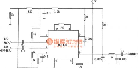
The picture shows the multiplying wave detector circuit. The circuit is single-side band AM signal detector. Its working principle is that it will multiply the received single-side band(SSB) signal by receiving end's restored carrier wave, and then the demodulation work will be done. In the figure, the manifold MC1496 is balanced modulator and demodulator. The circuit's output voltage is the product of input voltage signal and switching function provided by the carrier wave. The circuit has a sensitivity of 3 μV when it is operating in 9MHz IF frequency and the dynamic range is 90dB. (View)
View full Circuit Diagram | Comments | Reading(1601)
Audio Power Indicating Circuit Using Five-digit LED Display(FD502)
Published:2011/9/8 1:56:00 Author:Sue | Keyword: Audio Power Indicating Circuit, Five-digit LED Display
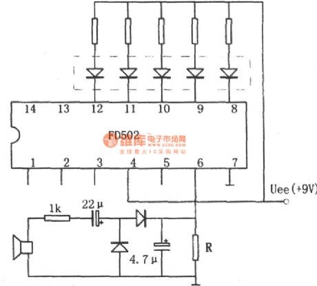
The picture shows the audio power indicating circuit which uses five-digit LED display. The circuit consists of level meter driver FD502 and five-digit LED display. The circuit can take out the audio signal's positive range variation which will form direct current level, and then by measuring the variation of the direct current level, the indicating audio power can be known. If the audio signal is too low, FD502 can be altered to FD501, which can drive LED after it is preamplified. FD502 and FD501 are domestic integrated circuits. FD501 has one preset amplifier and five comparators inside, while FD502 has no preset amplifier. (View)
View full Circuit Diagram | Comments | Reading(1345)
The pulse demodulator composed of gate circuit
Published:2011/9/9 18:23:00 Author:Ariel Wang | Keyword: pulse demodulator , gate circuit
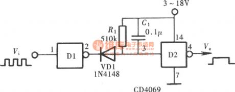
The pulse demodulator composed of CMOS six intervers CD4069 is seen as the chart.It is used to envelope detect for the plulse demodulator.
(View)
View full Circuit Diagram | Comments | Reading(749)
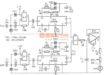
The comparative capacitance detector composed of CD4046
Published:2011/9/9 18:32:00 Author:Ariel Wang | Keyword: comparative, capacitance detector
The comparative capacitance detector is used to compare the capacitance to be detected and the standard capacitance.When the capacitance to be detected is larger or smaller than the standard capacitance,it can bedetected quicklywhether the capacitance of some products is comform to the design standard.In this way it can ensure the product quality as demanded.Other circuit composition is seen as the chart.
(View)
View full Circuit Diagram | Comments | Reading(1271)
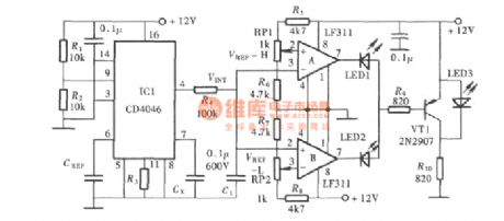
The phase detector composed of CD4046
Published:2011/9/9 18:36:00 Author:Ariel Wang | Keyword: phase detector
ThePhase detector composed of CD4046 is used to detect the phase difference of sine calibrate signal with two same frequency but different phase.Other circuit composition is seen as the chart.
(View)
View full Circuit Diagram | Comments | Reading(4470)
the frequency calibrator composed of CD4046
Published:2011/9/9 19:44:00 Author:Ariel Wang | Keyword: frequency calibrator
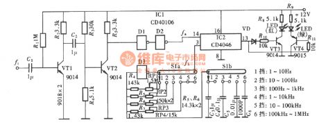
You can make up a frequency calibrator by using the frequency locking characteristics of the phase-locked loop circuit.Other circuit composition is seen as the chart.The circuit consists of input signal amplification and shaping circuit, the standard frequency signal circuit, the signal comparative detection circuit and detection result indication circuit.
(View)
View full Circuit Diagram | Comments | Reading(1580)
The responsiveness tester composed of CD4017
Published:2011/9/9 19:50:00 Author:Ariel Wang | Keyword: responsiveness tester
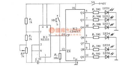
The responsiveness tester used to test response capabilities and training of human rapid-response capability.It has a variety of structural forms.As shown in the chart the responsiveness tester uses the decimal counterCD4017 and light-emitting diodes.The structure is relatively simple, it can be used as a toy to train and test the children's rapid response capability. (View)
View full Circuit Diagram | Comments | Reading(836)
Scanning Oscillating Circuit Composed of TL082
Published:2011/9/4 7:30:00 Author:Joyce | Keyword: Scanning, Oscillating
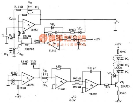
This is a scanning oscillating circuit composed of TL082, which can get voltage proportional to the control voltage Uc. If adding an antilog circuit when scanning logarithms, it can be used as an automatical scanner of sawtooth wave input and voltage-controlled oscillator of low frequency sine output. The circuit is composed of Wien bridge oscillating circuit and variable resistances (photo resistances within optical couplers PC1 ~ PC3) etc. Wien bridge circuit has a resistance capacitance network with frequency selectivity. The gain of A1 is about 3,and that of the loop is 1.Its oscillation frequency f is: f = 1 / (2πR0C0), in which C0 = C1 = C2, R0 = R1 + RG1 = R2 + RG2.
(View)
View full Circuit Diagram | Comments | Reading(1766)
Direction Displayer of Tape Movement
Published:2011/9/4 7:30:00 Author:Joyce | Keyword: Direction, Displayer, Tape, Movement
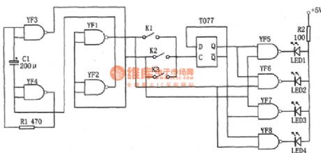
As shown in the figure is a direction display circuit of tape movement. The circuit is composed of rectangular pulse generator, D flip-flop (T077), decode circuit, light emitting diodes LED1 ~ LED4 etc. The rectangular pulse generator is composed of NAND gates YF1 ~ YF4, and its output signal frequency is 1 ~ 3 Hz, which can be changed by adjusting the value of C1, R1. T077 is connected in a state of counting, which will dichotomise the signal output by the rectangular pulse generator. The decode circuit constitutes of NAND gates YF5 ~ YF8, and its output signal will control the display of the led. (View)
View full Circuit Diagram | Comments | Reading(594)
Radio Digital Ondoscope
Published:2011/9/4 7:29:00 Author:Joyce | Keyword: Radio Digital Ondoscope
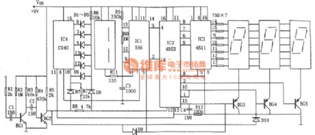
As shown in the circuit is a radio digital ondoscope circuit. It is composed of double time-base circuit 556( IC1), BCD code three bit counter IC2 (MC4553), 12 bit binary serial counter/frequency divider IC4 ( C040), BCD code seven segment lock /decode/driver and 4 digital luminescence tubes etc.
(View)
View full Circuit Diagram | Comments | Reading(1500)
| Pages:13/164 1234567891011121314151617181920Under 20 |
Circuit Categories
power supply circuit
Amplifier Circuit
Basic Circuit
LED and Light Circuit
Sensor Circuit
Signal Processing
Electrical Equipment Circuit
Control Circuit
Remote Control Circuit
A/D-D/A Converter Circuit
Audio Circuit
Measuring and Test Circuit
Communication Circuit
Computer-Related Circuit
555 Circuit
Automotive Circuit
Repairing Circuit