
Automotive Circuit
Index 3
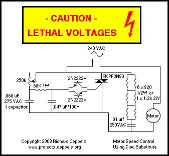
motor speed control
Published:2013/1/22 21:14:00 Author:muriel | Keyword: motor speed, control
View full Circuit Diagram | Comments | Reading(0)
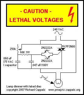
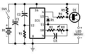
classic lamp dimmer circuit
Published:2013/1/22 21:13:00 Author:muriel | Keyword: classic lamp , dimmer circuit
View full Circuit Diagram | Comments | Reading(738)
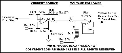
The Current Source and Buffer
Published:2013/1/22 21:12:00 Author:muriel | Keyword: Current Source, Buffer
View full Circuit Diagram | Comments | Reading(604)
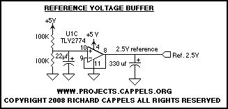
Reference Voltage Buffer
Published:2013/1/22 21:10:00 Author:muriel | Keyword: Reference Voltage Buffer
View full Circuit Diagram | Comments | Reading(664)
optional EIA-232 buffer
Published:2013/1/16 2:20:00 Author:muriel | Keyword: optional, EIA-232 buffer
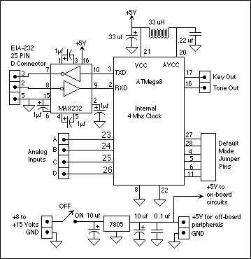
View full Circuit Diagram | Comments | Reading(681)
Automatic DC Motor Brake
Published:2013/1/7 21:12:00 Author:muriel | Keyword: Automatic, DC, Motor Brake
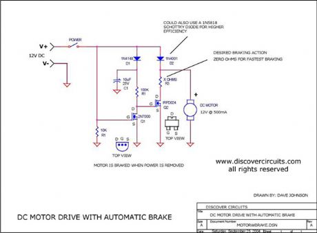
View full Circuit Diagram | Comments | Reading(1615)
Car Horn
Published:2012/12/24 21:21:00 Author:muriel | Keyword: Car Horn
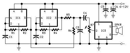
View full Circuit Diagram | Comments | Reading(974)
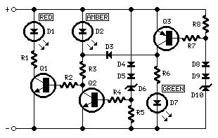
Tail/Brake Light Signal Cluster
Published:2012/12/21 21:28:00 Author:muriel | Keyword: Tail/Brake Light , Signal Cluster

View full Circuit Diagram | Comments | Reading(868)
Car Battery Saver
Published:2012/12/21 21:27:00 Author:muriel | Keyword: Car Battery Saver
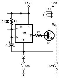
View full Circuit Diagram | Comments | Reading(834)
Brake Light Signal Module
Published:2012/12/21 21:26:00 Author:muriel | Keyword: Brake Light , Signal Module
View full Circuit Diagram | Comments | Reading(767)
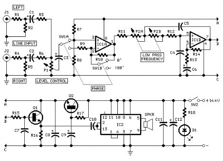
Car Subwoofer Driver 2
Published:2012/12/21 21:26:00 Author:muriel | Keyword: Car Subwoofer Driver
View full Circuit Diagram | Comments | Reading(1065)
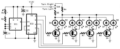
Sequential Turn Lights Driver
Published:2012/12/21 21:25:00 Author:muriel | Keyword: Sequential, Turn Lights, Driver
View full Circuit Diagram | Comments | Reading(1017)
Automotive Voltage Indicator
Published:2012/12/21 21:24:00 Author:muriel | Keyword: Automotive , Voltage Indicator
View full Circuit Diagram | Comments | Reading(736)
Park-Aid Modification
Published:2012/12/20 21:17:00 Author:muriel | Keyword: Park-Aid Modification
View full Circuit Diagram | Comments | Reading(718)
Park-Aid
Published:2012/12/20 21:16:00 Author:muriel | Keyword: Park-Aid
View full Circuit Diagram | Comments | Reading(165)
Speed-limit Alert
Published:2012/12/20 21:16:00 Author:muriel | Keyword: Speed-limit Alert
View full Circuit Diagram | Comments | Reading(843)
Motor Reversing Circuit
Published:2012/11/29 0:33:00 Author:muriel | Keyword: Motor Reversing Circuit
View full Circuit Diagram | Comments | Reading(771)
Multi Rocket Launcher
Published:2012/11/21 1:58:00 Author:muriel | Keyword: Multi, Rocket Launcher
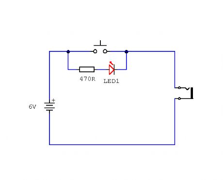
This launch controller can be used with low voltage battery igniters, which fire rocket engines in model rockets such as the Estes range. These circuits are electrical, only switches and contacts are involved. (View)
View full Circuit Diagram | Comments | Reading(719)
AGC circuit = Automatic gain control
Published:2012/10/11 2:22:00 Author:muriel | Keyword: AGC circuit
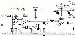
The automatic gain control circuit AGC provides a signal with less harmonics and additional amplification, between certain limits.As a result, it eliminates those intensity differences, annoying, and of speech music, which sometimes appear on radio and television.Field effect transistors T1 is used as a variable resistance. It’s value can vary from infinity to about 150Ω. It is in parallel with R3 and R4 together with, inducing the amplification of A1. Without FET, gainof A1 is about 20 dB.
AGC Automatic Gain Control circuit diagram
Amplification of A1 and A2 compensates damper losses: total agc circuit gain, with T1 blocked is 0 dB. Signals with a level lower than that set by P1 are amplified by a factor of maximum of 6.9 (= 17 dB amplification).
AGC components list semiconductors
D1 = 1N4148T1 = BF245CIC1 = TL072IC2 = TI071
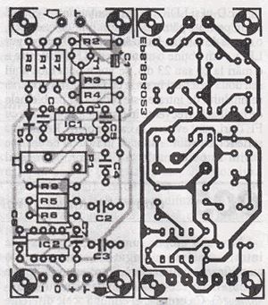
Automatic gain control PCB
(View)
View full Circuit Diagram | Comments | Reading(3324)
Safe 12V Car Adapter circuit
Published:2012/9/26 21:17:00 Author:muriel | Keyword: 12V, Car Adapter
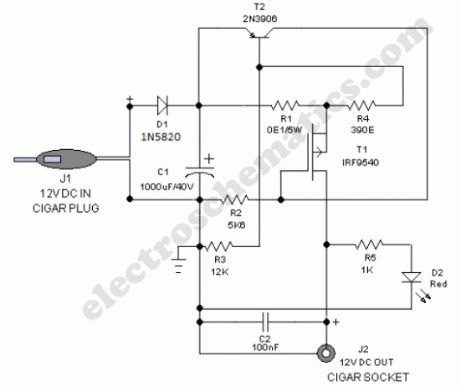
Safe 12V car adapter described here can be used to limit a +12 volt car battery current, available from the in-dash cigar lighter power port, to below 2.6 Amperes for use with portable electronic gadgets and travel chargers on long car journeys. This circuit will protect the car electric system against possible short circuits across the cigar power port.The 12 volts car adapter circuit is connected to the car +12V electric system via the cigar lighter plug J1. The +12V arrives on the board via a reverse voltage protection diode D1. Capacitor C1 decouples the input to the circuit. The current limited 12V output can be taken from the cigar lighter socket J2.Red LED (D2) is a simple power status indicator. After construction,boxed up the unit using a suitable ABS enclosure.
Working of this electronic fuse is very simple. Usually,the mosfet switch T1 is driven via resitor R2 and the 12V from the car battery is available at the output jack J2. The current flow through sense resistor R1 produces a voltage drop,which is at a certain level will force transistor T2 to switch on. This in turn switches off T1 somewhat and the output supply current to the connected electrical load is reduced to prevent costly disasters.
Note: Use a good quality heatsink for T1. Only for cars with negative ground only!
12 volts car adapter circuit diagram
(View)
View full Circuit Diagram | Comments | Reading(1576)
| Pages:3/164 1234567891011121314151617181920Under 20 |
Circuit Categories
power supply circuit
Amplifier Circuit
Basic Circuit
LED and Light Circuit
Sensor Circuit
Signal Processing
Electrical Equipment Circuit
Control Circuit
Remote Control Circuit
A/D-D/A Converter Circuit
Audio Circuit
Measuring and Test Circuit
Communication Circuit
Computer-Related Circuit
555 Circuit
Automotive Circuit
Repairing Circuit