
Automotive Circuit
Index 14
Output of Triangle Wave and Square Wave Voltage-controlled Oscillation Circuit Composed of LF356
Published:2011/9/4 7:28:00 Author:Joyce | Keyword: Output , Triangle Wave, Square Wave , Voltage-controlled , Oscillation
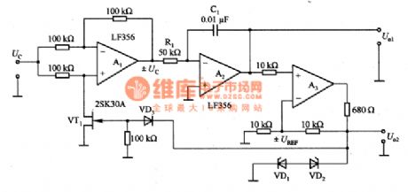
This is the voltage-controlled oscillation circuit of triangle wave and square wave output composed of LF356. Voltage controlled oscillation circuit can be used as PLL circuit and scanning oscillation circuit. The circuit constitutes of polarity commutation circuit VT1, inverse integrator A2 and lag comparator A3 etc. VT1 constitutes a polarity commutation circuit, which works by switch. A1 can work in phase and inverse alternatively. When VT1 breaks over, A1 forms an inverting amplifier; when it cuts off, A1 forms an inphase amplifier. Integral circuit A2 can integrate voltage 士Uc which have been polarity commutated.
(View)
View full Circuit Diagram | Comments | Reading(1480)
The regulator: DC-DC circuit and power supply monitor pin and its main features DS1832
Published:2011/9/10 18:59:00 Author:Seven | Keyword: regulator, power supply, monitor pin
The DS1832 voltage monitorThe working voltage is 3.3V; the halt and restart failure micro-computer; the microprocessor restarts automatically after the power supply fault is gone; it is used in external overload monitor keys; the monitor precision is 10%Vcc or 20%Vcc; the working temperature is -40~85℃; it can replace DS1232. The definitions of the main pins are as follows:PBRST : input by pressing the reset key; TD: the time delay setting; TOL: selecting the 10%Vcc or 20%Vcc monitor; PBRST: triggering input.
(View)
View full Circuit Diagram | Comments | Reading(690)
The main features of the amplifier pin signal--TL070/A JFET input op-amp
Published:2011/9/3 1:00:00 Author:Borg | Keyword: amplifier pin signal, JFET, input op-amp
TL070/A JFET input op-amp The input distortion voltage is 3mV; temperature drift is 10μV/℃; the biased current is 5pA; the gain band width is GB=3MHz; the rotating speed rate is 13V/μs; noise is 18nV/√Hz(1kHz); the differential mode input voltage is ±30V; the common input voltage is ±15V; the power consumption is 680mW.
(View)
View full Circuit Diagram | Comments | Reading(561)
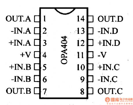
The main features of the amplifier pin--the medium separation JFET op-amps of OPA404
Published:2011/8/23 22:35:00 Author:Borg | Keyword: amplifier pin, JFET op-amps
(View)
View full Circuit Diagram | Comments | Reading(723)
the winding circle number measuring instrument composed of 555
Published:2011/9/9 9:08:00 Author:Ariel Wang | Keyword: winding, circle number, measuring instrument
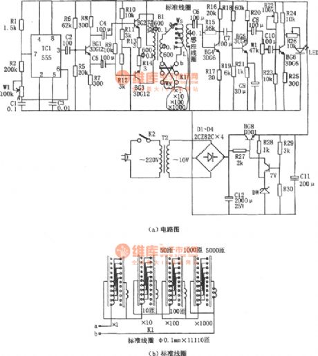
The measurement of the winding adopts the principle of magnetic pressure comparison .When the alternating current I goes to the winding which is to be measured and the standard winding Ws,the total magnetic motive force is:Vm=(Ws-Wx)i as two windings are series opposing .If Ws=Wx,then Vm=0.You can estimate the winding number to be measured by the standard winding number known.PSG is the multivibrator type oscillator composed of R1,R2,W1 and C1.The oscillation frequency is f=1.44/(R1+2R2+2Rw1)C1.The frequency range of parameter in the chart is 40~70Hz.You can adjust the oscillation frequency of potentiometer W1 to 50Hz. The drive stage is the class A push pull stage of power amplifier composed of BG2,BG3 and B1.
(View)
View full Circuit Diagram | Comments | Reading(662)
the machine which used to drive cats and dogs
Published:2011/9/9 9:12:00 Author:Ariel Wang | Keyword: cats, dogs, driver
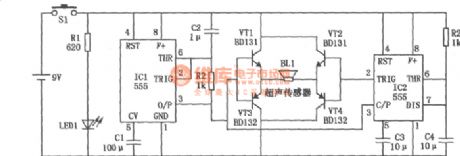
The circuit of the machine which used to drive cats and dogs is seen as the chart.It emits high-power ultrasonic which is safe to human beings.In this way,themachine reaches its goal to threat and drive cats and dogs .And it can keep them away.
(View)
View full Circuit Diagram | Comments | Reading(742)
Frequency Synthesizer Circuit Composed of MSM5820RS
Published:2011/8/25 7:42:00 Author:Sue | Keyword: Frequency Synthesizer
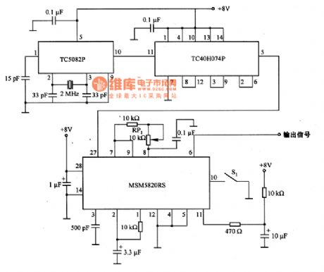
The picture shows the frequency Synthesizer circuit which is composed of MSM5820RS. The circuit uses 400HZ as center and it realises ±10% frequencyregulation by adjusting FP1's resistance value. S1 is reset switch. The oscillating circuit of 2MHz which is composed of TC5082P and crystal will output frequency signal of 500KHZ through pin 5 after it is frequency divided by TC40H074P. The signal will be put on MSM5820RS's pin 27 and then it will output signal from pin 6.
(View)
View full Circuit Diagram | Comments | Reading(4557)
Oscillating Circuit Composed of SN7490
Published:2011/8/25 7:42:00 Author:Sue | Keyword: Oscillating Circuit
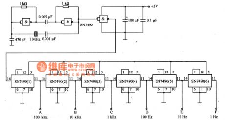
The picture shows the oscillating circuit which is composed of SN7490. In the circuit, the oscillating circuit uses TTL GATE circuit with a oscillate frequency of 1MHZ. When the six frequency dividing circuits SN7490 are connected in parallel, they can divide frequency and generate a frequency signal of 1HZ. The circuit's A,B,C,D,E,F terminals will output signals of frequency of 100kHZ, 10kHZ, 1kHZ, 100HZ, 10HZ and 1HZ. (View)
View full Circuit Diagram | Comments | Reading(3713)
Oscillating Circuit Composed of TC5082P
Published:2011/8/25 7:45:00 Author:Sue | Keyword: Oscillating Circuit
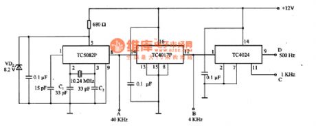
The picture shows the oscillating circuit which is composed of TC5082P. TC5082Pis a kind of integrated circuit which is used by PLL frequency synthesizer with 12 grade frequency divided circuit inside, and it has a wide use range. If the crystal oscillator's frequency is 10.24KHZ, then TC5028P's pin 8 can outputa signal of frequency of 40kHZ and its pin 7 can output a signal of frequency of 10kHZ, pin 6 can output a signal of frequency of 5kHZ, pin 4 can output a signal of frequency of 2.5 kHZ. If TC4017 and TC4024 are connected, then TC5028P's pin 8 will output a signal of frequency of 40kHZ, which will output a signal of frequency of 4KHZ on B terminal after it is frequency divided by TC4017P10.
(View)
View full Circuit Diagram | Comments | Reading(1957)
Rolling Circle Motive Display Circuit Composed of CD4017
Published:2011/8/25 7:44:00 Author:Sue | Keyword: Rolling Circle, Motive, Display
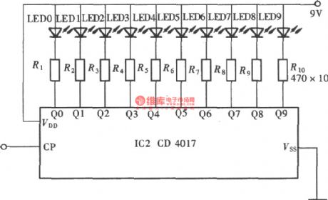
As seen in the figure, because of CD4017's output trait thatone of its10 output terminals will output high level while the other nine terminals all output low level, CD4017 is connected to be sink current output condition to constitute a rolling circle display circuit. (View)
View full Circuit Diagram | Comments | Reading(2583)
Sine Wave Oscillating Circuit Compsoed of MJM5534
Published:2011/8/25 7:46:00 Author:Sue | Keyword: Sine Wave, Oscillating Circuit
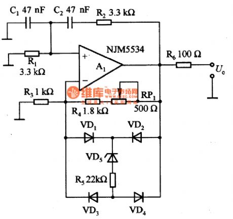
The picture shows sine wave oscillating circuit which is composed of MJM5534. This a kind of wien bridge sine wave oscillating circuit. If R1=R2=R,C1=C2=C, then oscillating frequency is 1/(2πRC). Wien bridge will make amplitude stay stable, so there is great distortion. But when it is converted to low frequency which is below 10HZ, the amplitude will be stable in short time. According to the component parameter in the picture, by adjusting RP1's resistance value, output voltage's effective value is 5V. By changing C1's value, its distortion rate will be 0.7%-0.9% in the frequency range of 10HZ-100KHZ. If output voltage's effective value is adjusted to 3V, then the distortion rate can be reduced to 0.1%. (View)
View full Circuit Diagram | Comments | Reading(761)
Voltage/Frequency Converter Counting Display Circuit Composed of 555
Published:2011/8/25 7:45:00 Author:Sue | Keyword: Voltage/Frequency Converter, Counting Display
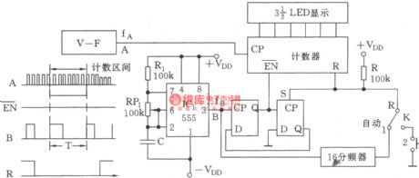
The picture shows the voltage/frequency converter counting display circuit composed of 555. (View)
View full Circuit Diagram | Comments | Reading(620)
the circuit of the granary full reminder for the combine harvester (1)
Published:2011/8/11 4:39:00 Author:Ariel Wang | Keyword: granary full reminder, combine harvester
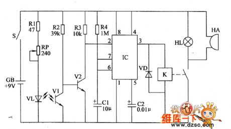
When the granary is not full,V1 is conducted by the infrared light emitted by VL.V2 is stopped.The pin-2 of IC becomes high level.The pin-3 outputs low level.It is released.HL isn’t lighted.HA doesn’t give a sound.When the granary is full,the food in granary covers YL and VI.The resistence of VL is large.1 and 2 are conducted.The high level of IC’s pin-2 becomes low level. The monostable circuit turns over.The pin-3 of IC outputs high level.K is conducted to pull in.The normally open contacts are conducted.HL is lighted.HA gives out alarm sound.It tells the driver that the granary is full. (View)
View full Circuit Diagram | Comments | Reading(610)
the diode and triode online testing machine composed of 556
Published:2011/9/8 6:15:00 Author:Ariel Wang | Keyword: diode, triode , online testing machine
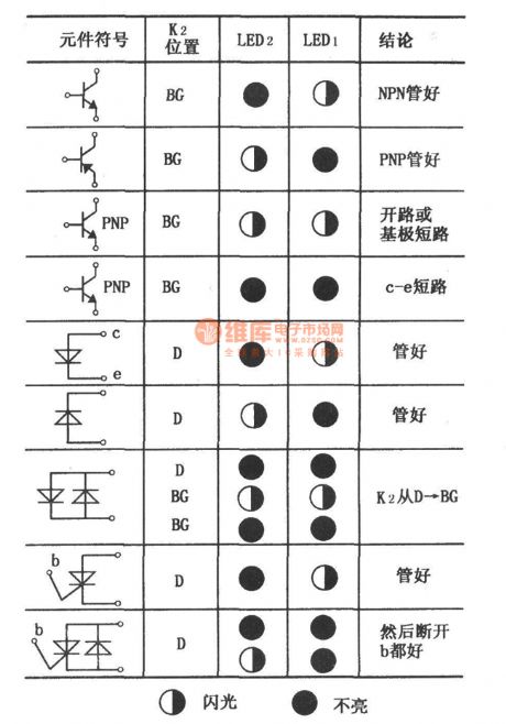
The monostable trigger is composed of the other half of 556.The pin ⑤ and pin ⑨ of 556 output 5Hz alternating square wave of which the peak voltage with a pair of reversed polarities is 9V . When the power supply gets through,if LED1 and LED2 give out light alternately without devices (the tubes),then the testing signal souce is normal.If you want to indicate whether the diode and triode are OK or not,distinguish the polarity of the tubes,testing conditions,whether LED1 and LED2 are lighted or not and the testing results quickly with the tubes(i.e. There are lines),you can refer to the chart. (View)
View full Circuit Diagram | Comments | Reading(660)
the quick SCR testing machine composed of 555
Published:2011/9/8 6:15:00 Author:Ariel Wang | Keyword: SCR, testing machine

The oscillation frequency shown in the chart is about 1Hz.The charging time t of the capacitor C =0.693(R1+R2)C.The discharge time t of the capocitor C =0.693R2C.They are quite alike.So the duty cycle of the output pulses is near 1:1. LED1,resistor R4,SCR,transistor BG2 form a closed circuit when 555 outputs high level as AN is pressed and SCR is plugged in.LED1 gives out light.LED2,R4,SCR and BG1 form a closed circuit when 555 outputs low level.LED2 gives out light.It indicates the SCR is good. (View)
View full Circuit Diagram | Comments | Reading(1425)
the digital capacitor testing machine
Published:2011/9/8 6:15:00 Author:Ariel Wang | Keyword: digital capacitor, testing machine
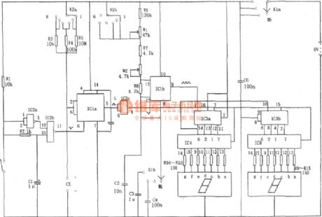
the counting circuit IC3 adopts double BCD addition counter CD4518.IC4 and IC adopt BCD-seven-segment-latch,decoding driver CD4518.LED adopts common cathode LED which matches CD4511.You can adjust the potentiometer W1,W2 to correct the testing machine.In this way,you can get the frequency signals of 9.09kHz and 0.909kHz.You can put the selectorswitch K2 to position 1 .Then the potentiometer W1 is shortcut with resistance R6.You can adjust the potentiometer W2.In this way the output cycle becomes 1.1ms(9.09kHz).Then you can put the selectorswitch K2 to position 2 .You can adjust the potentiometer W1.In this way the output cycle becomes 11ms(0.909kHz).
(View)
View full Circuit Diagram | Comments | Reading(1468)
the multifunction electronic probe and instrument composed of 555
Published:2011/9/8 6:16:00 Author:Ariel Wang | Keyword: multifunction, electronic probe , instrument
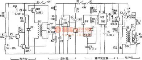
You can plug two electrodes in CK1.The oscillation frequency becomes higher as the resistance of the points is low.When the distance between the points and the detectors becomes farther,the frequency becomes lower.In this way it is to reach the points detection.The timer is made up by ICl(555),R5,W2 and C3.The pulse generator is the multivibrator composed of W4,R8,D3,D4,W3 and C4.The oscillation frequency is f=1.44/(Rw4+R8+Rw3)C4.You can adjust the potentiometer W3 and W4 to change the oscillation frequency and duty ratio.
(View)
View full Circuit Diagram | Comments | Reading(657)
the radiation detector (CD4011)
Published:2011/9/8 6:22:00 Author:Ariel Wang | Keyword: radiation
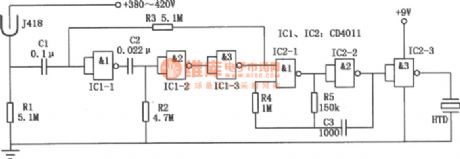
It is the radioactive beam monitor circuit.It consists of radiation testing sensor,two input ends and four NOT-AND gates.It could be used to detect ray α、γ、β and X.It has high sensibility.When low-level radiation detected,the detector will give out alarm sound every now and then.When the radiation is over standard,it will give out alarm sound constantly.
(View)
View full Circuit Diagram | Comments | Reading(1629)
The multifunction physiotherapy
Published:2011/9/8 6:17:00 Author:Ariel Wang | Keyword: multifunction , physiotherapy
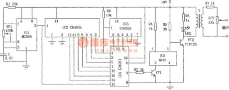
The multifunction physiotherapy circuit is shown as the chart.Its electrical stimulation pulse frequency could increase(or decrease) from 2 to 256Hz.Every frequency it could last 8s.It transforms automaticly.It works in cycle.
(View)
View full Circuit Diagram | Comments | Reading(1680)
The Transistor Characteristic Curve Drawer Circuit Composed of 555
Published:2011/9/6 4:44:00 Author:Felicity | Keyword: Transistor Characteristic Curve Drawer
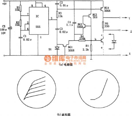
The circuit shown in figure one consists of sawtooth wave generator and step wave generator.To draw the transistor characteristic curve two kind of voltage are needed. First is the step wave that put on pole b to generate different base current.Second the sawtooth wave that put on pole c, its periodic time corresponding to the step wave to draw the transistor output characteristic curve,the Ic-Vce characteristic curve.The sawtooth generator consists of multivibrator (IC(555)、R1、R2、C1) and intergrator(C2,R3).And the oscillation frequency of the multivibrator is f=1.44/(R1+2R2)C1. (View)
View full Circuit Diagram | Comments | Reading(1446)
| Pages:14/164 1234567891011121314151617181920Under 20 |
Circuit Categories
power supply circuit
Amplifier Circuit
Basic Circuit
LED and Light Circuit
Sensor Circuit
Signal Processing
Electrical Equipment Circuit
Control Circuit
Remote Control Circuit
A/D-D/A Converter Circuit
Audio Circuit
Measuring and Test Circuit
Communication Circuit
Computer-Related Circuit
555 Circuit
Automotive Circuit
Repairing Circuit