
Automotive Circuit
Index 16
Car emergency flashlight circuit diagram
Published:2011/9/6 4:21:00 Author:Lucas | Keyword: Car emergency flashlight
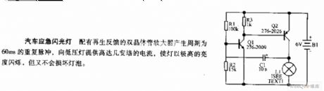
The dual-transistor amplifier with renewable feedback generates the repetition pulse with period in 60ms, and it provides several ampere of current for low-voltage lamp to make the lamp flash in high brightness, and it will not damage the bulb.
(View)
View full Circuit Diagram | Comments | Reading(1098)
Photoelectric Automatic Counter
Published:2011/8/12 6:54:00 Author:Sue | Keyword: Photoelectric, Automatic, Counter
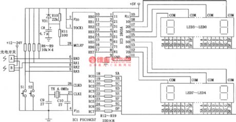
The picture shows the working principle of the photoelectric automatic counter. It is made of singlechip PIC16C57. It is suitable in industrial automated production and has some use values. (View)
View full Circuit Diagram | Comments | Reading(1007)
Short Circuit Tester
Published:2011/8/11 6:31:00 Author:Sue | Keyword: Short Circuit, Tester

The picture shows the short circuit tester. As seen in the picture, it can test any short circuit on the cable or printed circuit board conveniently,after the components are welded.When the tester approaches the short circuit point, the tone will become higher accordingly. (View)
View full Circuit Diagram | Comments | Reading(977)
Square Wave and Triangular Wave Generating Circuit
Published:2011/8/11 6:00:00 Author:Sue | Keyword: Square Wave, Triangular Wave, Generating
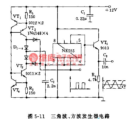
Figure 5-11 Triangular wave, square wave generating circuit (View)
View full Circuit Diagram | Comments | Reading(677)
General Active Filter Circuit
Published:2011/8/19 6:52:00 Author: | Keyword: General, Active Filter
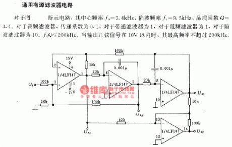
In the circuit, its center frequency f0=3.4kHz, and the trap frequency fe=9.5kHz, the quality factor Q=3.4. For the high frequency filter, the transmittance is 0.1. For the band pass filter, it's 1. For the low frequency filter, it's 1. For the trap frequency filter, it's 10. f0Q≤200kHz. When the output sine wave signal is beyond 10v, its highest frequency is lower than 200kHz. (View)
View full Circuit Diagram | Comments | Reading(697)
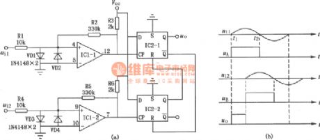
Multivibrator Circuit Composed of 74HC123
Published:2011/8/23 7:17:00 Author: | Keyword: Multivibrator
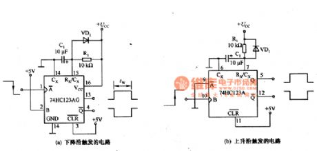
The picture shows the multivibrator circuit which is composed of 74HC123. In the figure 6-18, (a) shows the circuit of 74HC123's Q andits output pulse when the input signal's trailing edge is put on A terminal. (b) shows the circuit of 74HC123's Q andits output pulse when the input signal's rising edge is put on B terminal. The output pulse's width Tw is determined by R1,C1, which means Tw=R1C1. C1's accumulated electric charge is released through pin15 or pin7. When C1's capacitance is large, in order to reduce pin7's or pin 15's discharge current, R1 can be connected to the diode VD1 in parallel. C1's discharge current can get into +UCC directly through VD1 so that it can protect 74HC123. (View)
View full Circuit Diagram | Comments | Reading(7579)
LED Electronic Clock with Six Functions
Published:2011/8/11 6:41:00 Author:Sue | Keyword: LED Electronic Clock, Six Functions
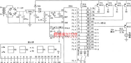
The picture shows the LED electronic clock with 6 functions which is composed of XY01 module. Itcandisplay month, day, hour, minute, second and it has a quarter-bell. (View)
View full Circuit Diagram | Comments | Reading(698)
Inductively coupled CUK power conversion circuit
Published:2011/8/31 2:43:00 Author:John | Keyword: Inductively coupled CUK power conversion
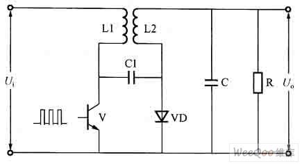
It should be noted that coupled adapter in the figure still uses the symbols of ordinary AC transformer. But in fact there are essential differences between the two: ① DC current can be through the coupled adapter; ②secondary current flow of coupled inductor is on the contrary of that of the AC transformer. As the coupling way only affects the exchange properties, the inductively coupled CUK can maintain the basic characteristics of all transformations, and as well as playing an instant emotional role of energy transfer.
(View)
View full Circuit Diagram | Comments | Reading(1265)
CUK power conversion circuit
Published:2011/8/31 2:01:00 Author:John | Keyword: power conversion
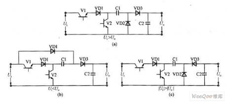
It is obvious to find that the three power conversion circuits described above have a common characteristic. Excluding the role of output capacitor, inductance is only needed to transfer energy storage inside people to the load in switching process by the power switching devices. Thus, they are all belonging to the inductive power conversion circuit. Different combinations of the capacitor and diode can also achieve three kinds of circuits which are featured of buck, boost, polarity inversion. They are also called the so-called capacitive energy transfer power conversion circuit. The principle circuit is as shown.
(View)
View full Circuit Diagram | Comments | Reading(737)
the portable hearing aid
Published:2011/8/23 23:47:00 Author:Ariel Wang | Keyword: portable, hearing aid
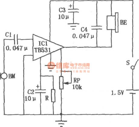
The capacitor C3 is used to weaken the high frequency in earphone BE.C4 is the power supply filter capacitor.RP is the potentiometer for volume control.The audio signal from the microphone BM is multi amplified by the hearing aid application specific integrated circuit TB5318.Then it drives the earphone BE to play.As the in-circuit IC1's gain is high,you should pay attention to the layout and routing of the whole machine component.It is to avoid self-excitation.The value selection of the resistance R's pin② of IC1 has something to do with the integrated circuit Sub-block value.You should select it within the range of 360kΩ~1MΩ.BE should adopt high-resistance earphone.
(View)
View full Circuit Diagram | Comments | Reading(2892)
the music hypnosis
Published:2011/8/24 0:08:00 Author:Ariel Wang | Keyword: music, hypnosis
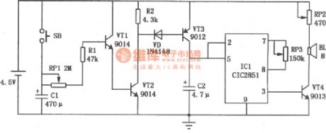
When the switch button SB gets through,C1 is charging.VT1 and VT2 are conducted.When SB is disconnected,VT1 and VT2 could stay conducted as C1 discharges to VT1 by RP1 and R1.VT3 is conducted because it gains forward biased current from polar c and e of VT2 through diode VD.IC1 works.The pin③ outputs music signal.The signal is amplified by VT4,then it drives the horn to give out a sound.The horn will play the music on and on in certain time as the pin② of IC1's trigger end connects to the positive electrode.In this way,it reaches the goal of hypnosis.The playing speed is adjusted by RP3.
(View)
View full Circuit Diagram | Comments | Reading(617)
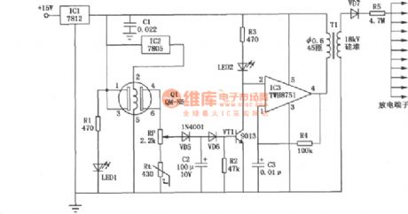
The effective ozone generator
Published:2011/8/24 0:43:00 Author:Ariel Wang | Keyword: effective, ozone generator
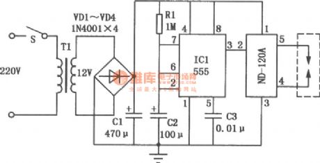
The ozone is a strong oxidizer.It has the ability to sterilize,bleach,deodorize and oxygenate.The specific circuit of the effective ozone generator is shown as the chart.The power transformer outputs +12V voltage time-base provides power supply to the integrated circuit 555 and ozone generater component ND-120A after it is commutated.IC1,R1 and C2 made up the monostable oscillator.You can adjust the value of R1 and C2 to change the oscillation frequency of IC1.The pin③ outputs oscillation impulse after IC1 oscillates.It stimulates ozone components.Then the pin④ and pin⑤ drive the ozone chips directly.The circuit can generate 100~150mg ozone every hour.It could be used in the place with low ozone density.
(View)
View full Circuit Diagram | Comments | Reading(5246)
The electric biological wave physiotherapy
Published:2011/8/24 0:42:00 Author:Ariel Wang | Keyword: electric, biological wave, physiotherapy
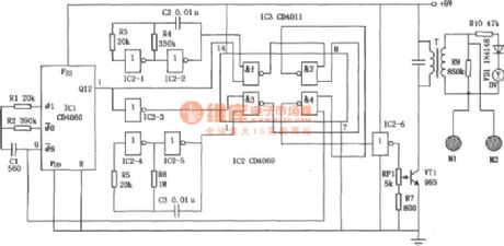
The electric biological wave physiotherapy circuit is shown as the chart.It can generate the electric signals of various composite frequency.It is good for the drugs absorption for the patients.It can also act on the human acupoint to do the treatment.
(View)
View full Circuit Diagram | Comments | Reading(1115)
the high sensitivity demonstration ammeter
Published:2011/8/25 23:09:00 Author:Ariel Wang | Keyword: high sensitivity , demonstration ammeter
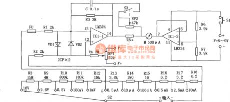
The ammeter could be applied for the experiments below:the Ohm law in closed circuit;the current distribution and amplification of the transistor;through the experiment,you can try to find the resistance of metal conducting wire and the length of the conducting wire,the relationship between the cross section area and the material,the relationship between the circuit voltage and the external resistance,the relationship between the series connection and parallel connection,the resistance measurement by using the voltammetric method,the electromotive force and resistance measurement by using the ammeter and the voltmeter and whether it generates induced current by single wire cutting of flux.The principle of the high sensitivity demonstration ammeter is seen as the chart. (View)
View full Circuit Diagram | Comments | Reading(942)
The simple consumption meter
Published:2011/8/25 23:15:00 Author:Ariel Wang | Keyword: simple, consumption meter
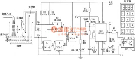
The simple consumption meter is made up of the sensor,the logic controller,the pulse generator and the swiching module.The circuit is seen as the chart.
(View)
View full Circuit Diagram | Comments | Reading(797)
the high precision region voltmeter
Published:2011/8/26 6:43:00 Author:Ariel Wang | Keyword: high precision , region voltmeter
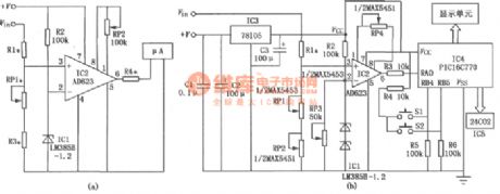
The circuit adopts the amplifier and high precision components.It improves the performance of the region voltmeter greatly.The inverting input of IC2 meter amplifier AD623 uses the high precision voltmeter reference IC1 as a standard.The noninverting input ends R1,RP1 and R3 enlarge the voltmeter to be measured.RP1 is the zero potentiometer .RP2 is the gain adjustment potentiometer.The amplifier output end is enlarged by the branched resistance R4.Then it connects the table head with the starting value and the termination value.You can select a region of voltmeter Vin to be measured.The starting value is V1.The termination value is V2.The voltmeter Vin to be measured changes within the range of V1~V2.
(View)
View full Circuit Diagram | Comments | Reading(1589)
The phase detection circuit
Published:2011/8/26 19:35:00 Author:Ariel Wang | Keyword: phase, detection
The phase detection circuit is made up of IC1(voltage comparator LM319) and IC2(double D trigger C013).The circuit has the advantages of simle struction,high precision and strong anti-jamming ability.Within the range of 0~30kHz,the detection precision is better than 0.1o.The output signal of the circuit could connect to the computer interface directly,and it can also connect to the digital voltmeter by low-pass filter.In this way,it forms the ideal phase detector.
(View)
View full Circuit Diagram | Comments | Reading(1387)
digital DC voltmeter
Published:2011/9/2 1:18:00 Author:Ariel Wang | Keyword: digital, DC

It is a three-bit semi-digital display DC voltmeter .It has the advantage of high accuracy,stable property and convenient usage.The measurement range is 0~1.999mV.The measurement accuracy is ±1mV. (View)
View full Circuit Diagram | Comments | Reading(3339)
The environmental Noise Monitor
Published:2011/9/3 22:25:00 Author:Ariel Wang | Keyword: environmental , Noise Monitor
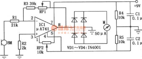
The environmental noise monitor circuit is mainly composed of high-gain op amp μA741. The noise signal will be indicated through the ammeter. Op-amp ICl is connected as noise amplifiers.The noise signal detected by the microphone BM will add to the inverting input of ICl.After it is amplified.It is rectified by the diode VDl ~ VD4 full-wave.And finally it makes the meter deflect. Thus it indicates the strength of environmental noise .When it is adjusted, the microphone should be short ended first , then you should adjust the zero potentiometer RP2.The ammeter indicates zero.You should adjust the potentiometer RPl.It can change the meter sensitivity. And the noise intensity corresponding to the meter scale value can be calibrated by a standard monitor.
(View)
View full Circuit Diagram | Comments | Reading(712)
Indoor Air Purifying Sets
Published:2011/8/23 0:46:00 Author: | Keyword: Indoor , Air Purifying Sets
The discharge end made up from needle-shaped material adopts open type.In this way it can reach the goal of increasing the density of negative oxygen ion and reducing the density of ozone.When the atmosphere is normal inside,the potential of the gas sensor Q1's pin④ and pin⑥ is low.VT1 is stopped.The potential of IC3's pin② is high.The oscillator stops working.There's no negative oxygen generated.Rt is negative temperature coefficient thermistor.It compensates the errors causing by gas sensor Q1 as the temperature changes.The potential RP is used to adjust the sensitivity of detecting harmful gas.
(View)
View full Circuit Diagram | Comments | Reading(620)
| Pages:16/164 1234567891011121314151617181920Under 20 |
Circuit Categories
power supply circuit
Amplifier Circuit
Basic Circuit
LED and Light Circuit
Sensor Circuit
Signal Processing
Electrical Equipment Circuit
Control Circuit
Remote Control Circuit
A/D-D/A Converter Circuit
Audio Circuit
Measuring and Test Circuit
Communication Circuit
Computer-Related Circuit
555 Circuit
Automotive Circuit
Repairing Circuit