
Automotive Circuit
Index 12
Remittent Oscillating Circuit with Good Linearity Controlled by Direct Current Voltage
Published:2011/8/25 7:49:00 Author:Sue | Keyword: Remittent Oscillating, Good Linearity, Direct Current Voltage
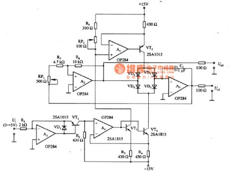
The picture shows the remittent oscillating circuit with good linearity which is controlled by direct current voltage. The remittent oscillating circuit controls C1's current and generates triangular wave. If the triangular wave is transformed into sine wave, then the circuit will become analog function generator circuit. The voltage/current change-over circuit which is composed of A3 and VT1 can transformed the input voltage into current. The current which is flowing through R1 is similar to VT1's collector's output current. R2=R3=R4, so A4's same-phase and phase reversal input terminals almost have the same level, and VT1's collector current and VT3,VT4's collector current are equal. (View)
View full Circuit Diagram | Comments | Reading(934)
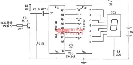
Week Digital Display Composed of CH233,CD4017B
Published:2011/8/25 7:49:00 Author:Sue | Keyword: Week, Digital Display
View full Circuit Diagram | Comments | Reading(1316)
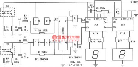
Highway Automatic Electronic Sign Board in the Nighttime
Published:2011/8/25 7:49:00 Author:Sue | Keyword: Highway, Automatic Electronic Sign Board, Nighttime

The picture shows the automatic electronic sign board circuit. When it is dark, the pilot light E3 will give out red light which indicates that there is danger. On the highway, when a car is near the dangerous area, the traffic sign which consists of pilot light E1,E2 will be displayed. At the same time, the pilot light E3,E4 will give out red and green flash light. When the car is away from the dangerous area, the pilot light E3 remains red, and the pilot light E1,E2 and E4 are off. The circuit consists mainly of acoustic control circuit, oscillating circuit and drive display circuit. (View)
View full Circuit Diagram | Comments | Reading(1149)
Eight-channel Voltage Tour Detection Circuit Composed of 555,CD4017,CH233
Published:2011/8/25 7:41:00 Author:Sue | Keyword: Eight-channel Voltage, Tour Detection
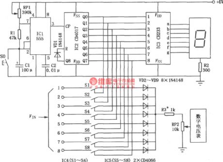
The picture shows the eight-channel voltage tour detection circuit. It uses digital tube to display the number of the line which is under detection, and then uses LED digital voltmeter to read directly the tour detection voltage. Every line has 10s to display the tour detection voltage. S0 can be used to display one line's voltage fixed value conveniently. (View)
View full Circuit Diagram | Comments | Reading(2495)
Sine Wave Oscillation Circuit with Stable Amplitude Composed of FET
Published:2011/9/8 1:47:00 Author:Sue | Keyword: Sine Wave, Oscillation, Stable Amplitude
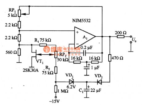
The picture shows the sine wave oscillation circuit with stable amplitude composed of FET. In the circuit, VD2 and C1 can rectify and filtrate the output sine wave and then make it direct current voltage. The voltage controls FET(VT1)'s grid electrode. FET works as variable resistor. If the output voltage becomes higher, then FET's grid electrode level becomes higher and the resistance value between the drain electrode and source eletrode becomes lower. Then the positive feedback factor which returns to A1's same-phase input terminal becomes smaller and output amplitude becomes smaller and returns to its old value which will make its amplitude stay unchanged. (View)
View full Circuit Diagram | Comments | Reading(951)
Electronic Signpost Composed of 555,CD4017
Published:2011/9/8 1:48:00 Author:Sue | Keyword: Electronic Signpost
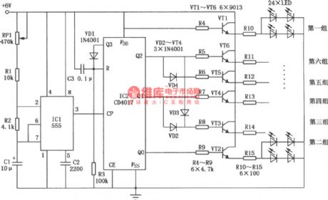
The picture shows the electronic signpost circuit. Its display circuit consists of 24 LED, which are arranged in 6 groups as arrow figure j from back to front. The electronic signpost uses time base circuit to generate pulse signal which will drive 6 groups of LED to dynamically display according to a certain law so that it can indicate the road direction. The circuit mainly consists of time base circuit 555, decimal counter CD4017 and display circuit. (View)
View full Circuit Diagram | Comments | Reading(2166)
Score Indicator(CD4027,CD4055,CD40192)
Published:2011/9/8 1:49:00 Author:Sue | Keyword: Score Indicator
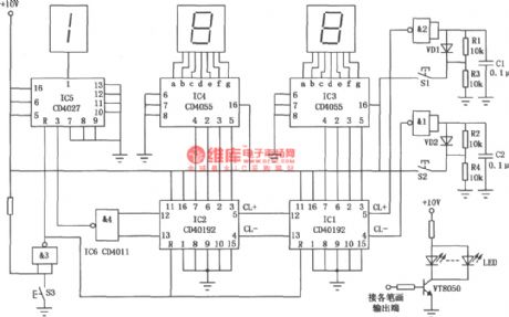
The picture shows the score indicator circuit. It is used to display the match score. The first digital tube has only 2 states, that is off or l . The two tubes behind can display ten states of 0 - 9 , so the score indicator can display as high as 199 scores. The circuit mainly consists of counter, decoding circuit, trigger circuit, display circuit and jitter buffer switch circuit. (View)
View full Circuit Diagram | Comments | Reading(4160)
Modulator Circuit Used by Test Signal Generator
Published:2011/9/8 1:48:00 Author:Sue | Keyword: Modulator, Test Signal Generator
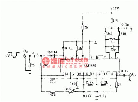
The picture shows the modulator circuit used by test signal generator. (View)
View full Circuit Diagram | Comments | Reading(977)
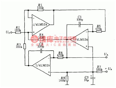
Third Terrace Asymmetric Filter Circuit
Published:2011/9/8 1:50:00 Author:Sue | Keyword: Third Terrace, Asymmetric, Filter
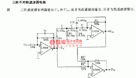
Third terrace filter has two output circuits--UA1, UA2. The former one is high pass filter output, and the later one is low pass filter output. (View)
View full Circuit Diagram | Comments | Reading(591)
Photo Couple Reversible Counting Display Circuit
Published:2011/9/8 1:49:00 Author:Sue | Keyword: Photo Couple, Reversible, Counting Display
The photo couple reversible counting display circuit uses photo couple devices as reversible counter which is made of optical sensor. It can count the devices with different operating direction by addition or substraction automatically. As seen in the figure, it is suitable to count the automatical continuous producted devices. In the circuit, the photo couple device is reflecting photo coupler. Infrared LEDs and photosensitive triode are connected at the angle of 35°, and the intersection point is 5mm from the photo coupler. When it is working, if the infrared LED's infrared ray is blocked by the thing forward, the infrared ray will be reflected back and be received by the photosensitive triode which will make the photosensitive triode connected. (View)
View full Circuit Diagram | Comments | Reading(1336)
Telephone Recorder(CD4511B,CD4518B)
Published:2011/9/8 1:49:00 Author:Sue | Keyword: Telephone Recorder
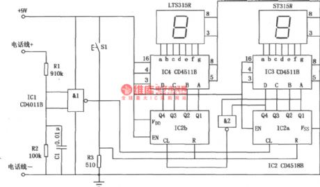
The picture shows the telephone recorder. It is mainly used to record and display the number of use times of the telephone so that the user can know more about the condition of service of the telephone. The recorder consists of two 7-segment digital tubes so the highest counting can be 99. The circuit has the reset button so it can reset the counting. (View)
View full Circuit Diagram | Comments | Reading(1860)
Audio Display Circuit Composed of CD4017
Published:2011/9/8 1:50:00 Author:Sue | Keyword: Audio Display
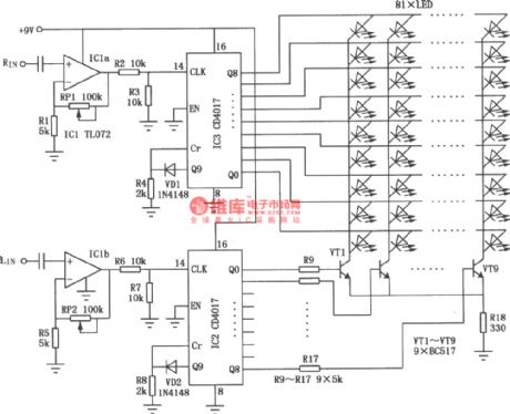
The picture shows the audio display circuit. It uses left and right stereo sound channels to control the display matrix which is composed of LED. Then the display matrix will jitter according to the audio signal's rhythm. The circuit consists of amplifier, counter and display circuit. (View)
View full Circuit Diagram | Comments | Reading(3830)
High-frequency Voltage Control Oscillator Circuit Composed of Transistor
Published:2011/9/8 1:49:00 Author:Sue | Keyword: High-frequency, Voltage Control, Oscillator, Transistor
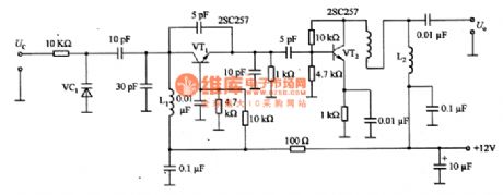
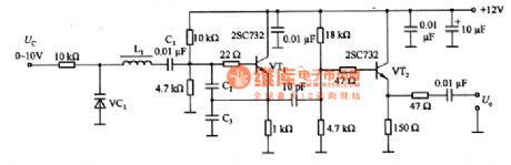
The circuit shows the high-frequency voltage control oscillator circuit composed of transistor. In figure(a), C2 and C3 provide VT1's emitter and base electrode with positive feedback.The oscillation frequency's reactance set value is low, which is about a resistance value of hundreds of ohm, and the goal is to prevent VT1 parameter's change from influencing the resonance oscillation circuit. The resonance oscillation frequency will vary as L1 and variode VC1's capacitance vary. The oscillation output impedance conversion through C4, which can prevent it from being influenced by load variation.
In figure (b), L1's value can be determined by empirical method according to the oscillation frequency. (View)
View full Circuit Diagram | Comments | Reading(1086)
Charge Display Circuit Composed of TB1004
Published:2011/9/8 1:50:00 Author:Sue | Keyword: Charge Display
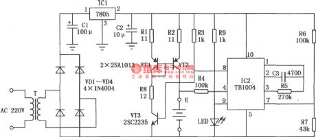
The charge display circuit is mainly used to charge nickel-cadmium cell. When cell is charged, it uses LED to indicate the charging state. When it is charged, the LED is not illuminated, and it indicates that it is being charged. When the charging is finished, the LED is not illuminated, and it indicates that the charging is finished. According to different states of the LEDs, the user can know the charging states better. The picture shows the charge display circuit which is composed of TB1004. (View)
View full Circuit Diagram | Comments | Reading(653)
Active Biquadratic Band-pass Filter Circuit
Published:2011/9/8 1:51:00 Author:Sue | Keyword: Active, Biquadratic, Band-pass, Filter
For all the active filter circuits, the center frequency is 1KHz, the quality factor Q=50, and the gain Kv=100(equal to 40dB). (View)
View full Circuit Diagram | Comments | Reading(911)
Staff Approaching Detector(LM385)
Published:2011/9/8 1:51:00 Author:Sue | Keyword: Staff Approaching Detector
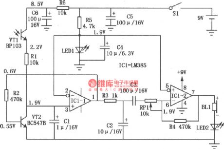
The picture shows the staff approaching detector circuit. The circuit uses ordinary photoelectric tube to detect the environmental light change caused by staff who go into the warning region, so that the detection function can be realised. (View)
View full Circuit Diagram | Comments | Reading(974)
Inductive Test Pencil(CD4069)
Published:2011/9/8 1:34:00 Author:Sue | Keyword: Inductive, Test Pencil
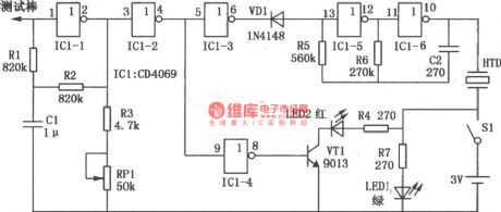
The picture shows the inductive test pencil. Its sensitivity is higher than common test pencil's sensitivity and it can test the wire's electrical property which the common test pencil can't do. IC1 is six phase inverter integrated circuit CD4069. Its inverter IC1-1 and the devices around will constitute a voltage amplifier with a high input impedance and a high gain. After the probe receives weak field signal, it is amplified and output by the amplifier and is transformed by phase-inverter IC1-2. Then it will controls the late grade circuit. The phase-inverter IC1-5,IC1-6 and resistor R5 and capacitor C2 will constitute multivibrator. Its work is controlled by the inverter IC1-3's working state. (View)
View full Circuit Diagram | Comments | Reading(1421)
Close-range Infrared Detection Circuit Composed of 555
Published:2011/9/8 1:52:00 Author:Sue | Keyword: Close-range, Infrared Detection
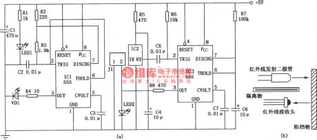
The figure (a) shows the close-range infrared detection circuit principle. The circuit realises detection of the controlled one by infrared ray close-range emitting and receiving. It can be used to realise close-range automatic instant control, such as bus's automatic door open/close control, washroom hand dryer's blowing control. The circuit consists of two parts: infrared ray emitting circuit and infrared ray receiving circuit. (View)
View full Circuit Diagram | Comments | Reading(1863)
Anti-inductive Crystal Oscillation Circuit
Published:2011/9/8 1:52:00 Author:Sue | Keyword: Anti-inductive, Crystal Oscillation Circuit
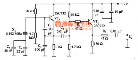
The picture shows the anti-inductive crystal oscillation circuit. In the circuit, C2 and C3 are positive feedback capacitor. The lower the frequency is, the larger the capacitance is. When the capacitance is 100pF, the oscillation frequency is 5-20MHz; C1 and C5 can be used to realise frequency fine tuning;VT2 is buffer circuit which can be used to prevent the frequency from changing while the load is changing; R1 and R2 are stablized resistor which can prevent emitter follower from oscillating abnormally. (View)
View full Circuit Diagram | Comments | Reading(685)
Metal Detector(MC14046B)
Published:2011/9/8 1:52:00 Author:Sue | Keyword: Metal Detector
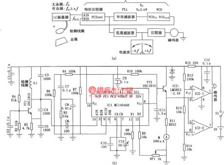
The picture shows the metal detector circuit. The detecting coil constitutes LC oscillating circuit. When the coil approaches the metal, the metal will have vortex inside which will make coil have varied inductance and the oscillating frequency of detector circuit will be changed accordingly. Figure (a) is the detector's functional block diagram. Figure (b) is the detecting circuit. (View)
View full Circuit Diagram | Comments | Reading(5304)
| Pages:12/164 1234567891011121314151617181920Under 20 |
Circuit Categories
power supply circuit
Amplifier Circuit
Basic Circuit
LED and Light Circuit
Sensor Circuit
Signal Processing
Electrical Equipment Circuit
Control Circuit
Remote Control Circuit
A/D-D/A Converter Circuit
Audio Circuit
Measuring and Test Circuit
Communication Circuit
Computer-Related Circuit
555 Circuit
Automotive Circuit
Repairing Circuit