
Automotive Circuit
Index 4
Car Interior Light Dimmer
Published:2012/9/25 21:30:00 Author:muriel | Keyword: Car Interior, Light Dimmer
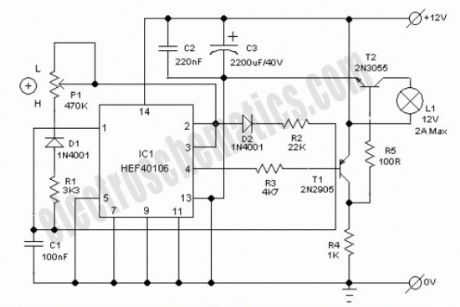
Ultra simple car interior light dimmer circuit of a pulse width modulated (PWM) energy saving dc lamp dimmer is described here. With the help of this circuit, you can control the intensity of the dome lamp in your car from near 5% to 90% using a single potentiometer. The circuit is designed for cars with negative ground.The circuit works off 12V dc supply from the car battery and is capable of driving dc incandescent lamps of wattages up to 24W!The design is based on IC1 (40106) astable multivibrator whose output is low for a period determined by R2 and high for a period determined by R1 and P1. Output from IC1 (at pin4) is applied to the base of transistor T1.Transistors (T1&T2) are switched on and the lamp is energized during the negative period of the output pulse of IC1. When the resistance of P1 is at maximum, the brightness of the lamp is at minimum level.
12V Light Dimmer Circuit Schematic
(View)
View full Circuit Diagram | Comments | Reading(2254)
Car Exhaust Meter
Published:2012/9/16 21:20:00 Author:Ecco | Keyword: Car Exhaust Meter
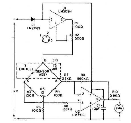
Bridge circuit contains two resistors lOO-ohm (R3 and R4), and two thermistors (Tl and T2). At room temperature, the resistance of T1 and 1'2 is about 2000 ohms. When they are each heated to 150 ° C by an RNA 10 current, the resistance value decreases to 100 ohms. So. the four elements include a bridge circuit. CO is a characteristic that conducts heat from a thermistor at a rate different from that of air. A thermistor, TI, is exposed to automobile exhaust, while the other, 1'2, is isolated in an environment of clean air. Unlike thermal conduction bridge imbalance. A voltage difference is caused between points A and C. A differential amplifier. VI, amplifies this difference and leads to the counter with a current sufficient to read the percentage of CO and air-fuel ratio. A control panel before the balance, R5, balances the bridge and calibrates the instrument. The calibration is performed when both thermistors are exposed to outside air. (View)
View full Circuit Diagram | Comments | Reading(0)
Car windshield wiper delay
Published:2012/9/11 21:03:00 Author:Ecco | Keyword: Car, windshield , wiper, delay
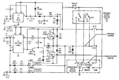
The circuit provides a windshield wiper delay, dynamic braking and windshield wipers when they reach the rest position. This prevents the blades passing, which could lead them to stop at a point where they interfere with the vision of drivers. With the original wiper switch off, switch turns on the MLS delay circuit and disconnects the wiring SIB from automobiles. When SI is turned off, the original wiring system and controls the delay circuit is bypassed. (View)
View full Circuit Diagram | Comments | Reading(1)
CAR IMMOBILIZER CIRCUIT
Published:2012/9/11 21:01:00 Author:Ecco | Keyword: CAR IMMOBILIZER
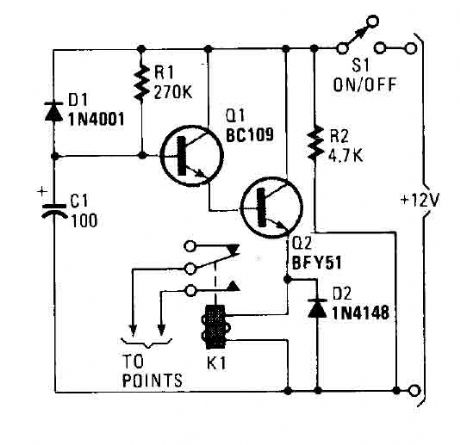
A flip of 51 puts the system in action. Power for the circuit is captured from the ignition switch, and circuit receives no power until the ignition switch is closed. When the camera is turned on, the capacitor C1 is charged and the emitter follower Darlington pair (formed by Q1 and Q2) are cut, so no voltage is applied to the relay (Kl), which serves as a load QL transmitter. normally open relay contacts are connected through the points of the vehicle. (At this point, the relay contacts are open and have no effect on the ignition system). Cl charges through R, causing the voltage at the base of Ql to rise steadily. (View)
View full Circuit Diagram | Comments | Reading(1)
Car Voltmeter Circuit
Published:2012/9/11 20:59:00 Author:Ecco | Keyword: Car Voltmeter
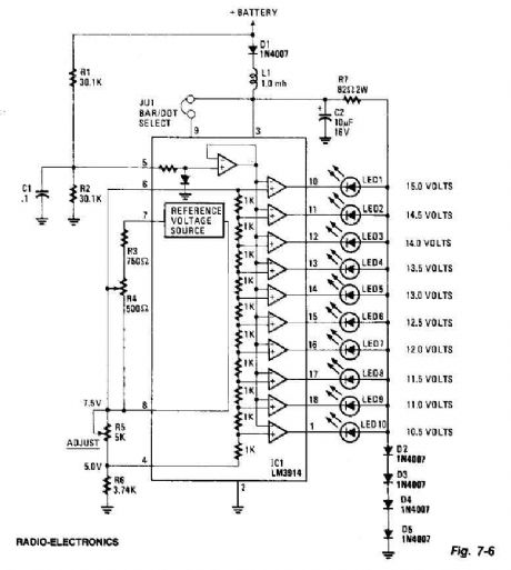
This screen uses ten LEDs to display a voltage range of 10.5 to 15 volts. Each LED represents a step 0.5wvolt tension. The heart of the circuit is the 3914 points LM / bar display driver. Trimming potentiometer R5 is adjusted so that 7.5 volts is applied to the upper side of the bulkhead. D2 resistor R7 and diode D5 to tighten the voltage applied to the LED 3 volts. A lowpass filter consisting of L1 and C2 guards against voltage spikes. The diode D1 is used to protect against reverse voltage where the voltmeter is connected backwards. (View)
View full Circuit Diagram | Comments | Reading(2036)
Automatic Headlight Brightness Switch
Published:2012/8/29 3:00:00 Author:Celina | Keyword: Automatic Headlight, Bipolar Output
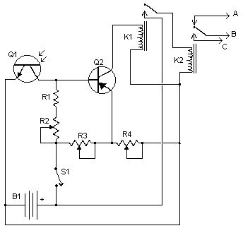
Driving the highway with your high-beam headlights can really increase your visibility, but can be a blinding hazard for other drivers. This simple circuit can be wired into your headlight switch to provide automatic switching between high and low beam headlights when there is oncoming traffic. It does this by sensing the lights of that traffic. In this way, you can drive safely with your high-beams on without blinding other drivers.
Notes
Q1 should me mounted in such a way so it points toward the front of the car with a clear line of site. Suitable places are on the dashboard, in the front grill, etc.
Adjust all the pots for proper response by testing on a deserted road.
S1 enables and disables the circuit.
B1 is, obviously, in the car already.
Before you try to connect this circuit, get a wiring diagram for your car. Some auto manufacturers do weird things with wiring.
Connection A goes to the high beam circuit, B goes to the headlight switch common and C connects to the low beam circuit.
source:aaroncake.net (View)
View full Circuit Diagram | Comments | Reading(1234)
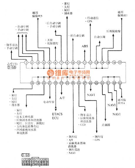
The Southeast Soveran relay connector ( J / C ) electrical system circuit diagram
Published:2012/7/2 3:50:00 Author:Ecco | Keyword: Southeast Soveran, relay connector , electrical system

View full Circuit Diagram | Comments | Reading(965)
Shenyang JinBei SY6474,SY6475A, SY6475 light bus width lamp, stop lamp, reversing lamp basic circuit diagram
Published:2011/8/10 4:10:00 Author:Nicole | Keyword: width lamp, stop lamp, reversing lamp
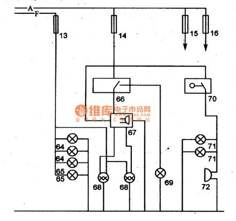
JinBei SY6474, SY6475 series of light buses are 4*2 rear wheel drive light bus, andthey have 10 seats(including driver).The highest speed is 110-115km/h, the economic speed is 50-60km/h, the minimum stable speed is 18km/h, the braking distance should not be more than 6.5m(when the speed is 30km/h), the maximum wading depth is 350mm, fuel consumption(L) is 11-11.5L, the maximum gradient is 30%-32%, the minimum turn diameter is not more than 13.5m.
JinBei SY6474、SY6475 light buses adopt SY492Q-2 motor; SY492Q-2 motor is only used in JinBei SY6475 light bus. The performance parameter can be shown in the JinBei 6480 light bus adopted motor. Its adopted battery is JinBei. 5Y6474、5Y6474A adopt 321 type starter with 12V、1·lkW; SY6475 adopts QD1239 type starter with l2V,O.95kW,and SY6475A adopts QDJl21 type starter with I2V,lkW. The motors are all JF series AC motors.
64-width lamp; 65-rear light; 66-stop lamp switch; 67-very low air brake buzzer; 68-braking signal light and rear light; 69-very low air brake alarm lamp; 70-reversing lamp; 72-reversing buzzer. (View)
View full Circuit Diagram | Comments | Reading(1085)
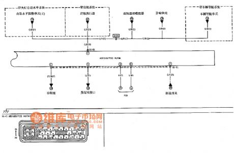
The 2.5L motor data sensor, heating oxygen sensor circuit diagram of commercial vehicle
Published:2011/8/10 4:07:00 Author:Nicole | Keyword: commercial vehicle, 2.5L motor , data sensor, heating oxygen sensor
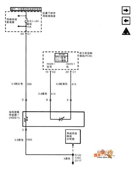
The circuit diagram of shanghai GM Buick commercial vehicle's(GL8) 2.5L motor data sensor, heating oxygen sensor
(View)
View full Circuit Diagram | Comments | Reading(1276)
Pulse dialing seven road infrared remote control circuit diagram
Published:2011/9/26 2:20:00 Author:Rebekka | Keyword: Pulse dialing , seven road infrared remote control
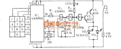

Infrared pulse coding table circuit:
Oscillation frequency:
Infrared receiver control circuit:
(View)
View full Circuit Diagram | Comments | Reading(1280)
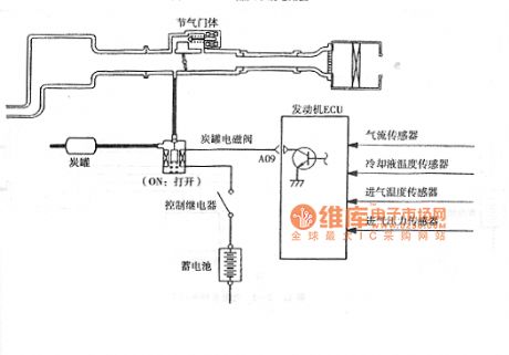
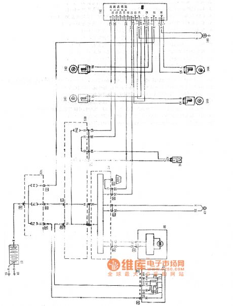
Hafei Simbo car charcoal canister electromagnetic valve circuit diagram
Published:2011/8/30 1:33:00 Author:Jessie | Keyword: Hafei Simbo car, charcoal canister, electromagnetic valve
View full Circuit Diagram | Comments | Reading(1372)
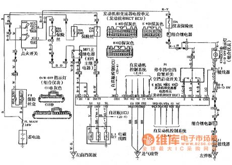
Sail automatic transmission circuit diagram
Published:2011/8/29 21:23:00 Author:Jessie | Keyword: Sail automatic transmission
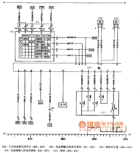
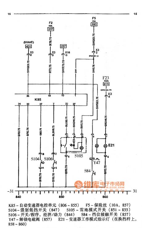
K85-automatic transmission electronic control unit (806 ~ 855), F5-fuse (10A, 857), S104-force low-end switch (847), S105-snow mode switch (851 ~ 855), S106-switch / process, economic / Power (844), S84-gear contact switch (857), Y47-unlock solenoid valve (857), E21-transmission mode indicator (on the shift lever, 858 - 860). (View)
View full Circuit Diagram | Comments | Reading(1052)
Saiou ABS circuit diagram
Published:2011/8/29 21:15:00 Author:Jessie | Keyword: Saiou ABS
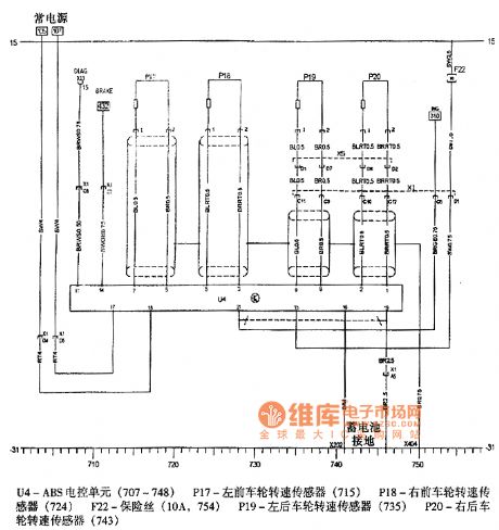
U4-ABS electronic control unit (707 ~ 748), P17-left front wheel speed sensor (715), P18-right front wheel speed sensor (724), F22-fuse (10A, 754), P19-left rear wheel speed sensor (735 ), P20-right rear wheel speed sensor (743). (View)
View full Circuit Diagram | Comments | Reading(908)
M6 car anti-lock braking system ABS traction control system TCS circuit
Published:2011/8/29 22:53:00 Author:Jessie | Keyword: ant-ilock braking system ABS, traction control system TCS
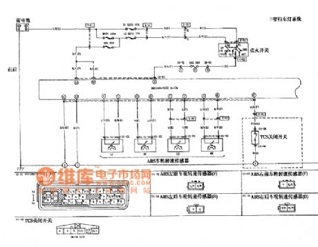
View full Circuit Diagram | Comments | Reading(1527)
Shaalis 2000 automatic transmission circuit diagram
Published:2011/8/29 22:52:00 Author:Jessie | Keyword: Shaalis , automatic transmission
View full Circuit Diagram | Comments | Reading(1195)
Siena ABS circuit diagram
Published:2011/8/29 22:51:00 Author:Jessie | Keyword: Siena ABS
View full Circuit Diagram | Comments | Reading(692)
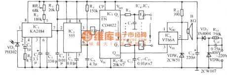
Car headlight automatic controller circuit composed of 555
Published:2011/11/3 1:21:00 Author:May | Keyword: Car headlight, automatic controller, 555
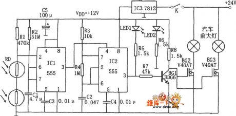
The diagram is car headlight automatic controller circuit. This controller consists of single-shot delay circuit ( IC1, Rl, R2、RD, C1), multivibrator ( IC2, R3, R4, C2) , intergrated circuit( 7812) , V-MOS power driving tubes BG2, BG3 to separately drive car's two headlight. The power source of this controller uses car's +24V storage battery, and it provides DC +12V voltage for IC1, IC2 afterregulation by IC3.
When the front has no opposite cars, photoresistor RD presents high level becasue it does not receive shine, then the corresponding IC1 resets because pin 2 is in high level, then pin 3 outputs low level.It makes IC2 reset because pin 4 is low level, pin 2 outputs low level, then BG1 stops, BG2, BG3 isbreakover, two headlights arelighten.
(View)
View full Circuit Diagram | Comments | Reading(2610)
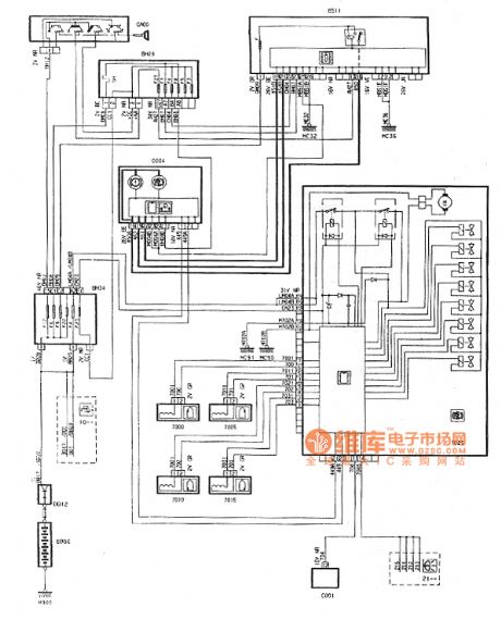
DPCA Picasso 1.6 L car ABS circuit diagram
Published:2011/8/29 22:38:00 Author:Jessie | Keyword: DPCA Picasso , 1.6 L car, ABS
View full Circuit Diagram | Comments | Reading(1190)
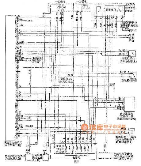
Passat 01N automatic transmission circuit
Published:2011/8/30 1:48:00 Author:Jessie | Keyword: Passat , automatic transmission
View full Circuit Diagram | Comments | Reading(1604)
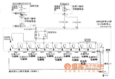
The circuit of Buick GL8 automobile ABS, bonding, ABS electronic control unit and traction electronic control unit EBCMEBTCM
Published:2011/8/30 1:47:00 Author:Jessie | Keyword: Buick , automobile ABS, bonding, electronic control unit , traction , electronic control unit, EBCMEBTCM
View full Circuit Diagram | Comments | Reading(802)
| Pages:4/164 1234567891011121314151617181920Under 20 |
Circuit Categories
power supply circuit
Amplifier Circuit
Basic Circuit
LED and Light Circuit
Sensor Circuit
Signal Processing
Electrical Equipment Circuit
Control Circuit
Remote Control Circuit
A/D-D/A Converter Circuit
Audio Circuit
Measuring and Test Circuit
Communication Circuit
Computer-Related Circuit
555 Circuit
Automotive Circuit
Repairing Circuit