
Circuit Diagram
Index 365
1kHz to 1MHz sine oscillator circuit
Published:2012/8/21 21:03:00 Author:Ecco | Keyword: 1kHz to 1MHz , sine oscillator
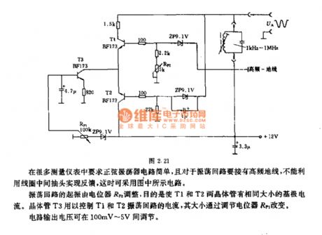
Sinusoidal oscillator circuit issimple in many measuring instrument, and oscillation loop should be connected to a high-frequency ground, and it can not use the coil center tap to achieve the feedback, in this case it can use the circuit shown as figure. The oscillation starting of shock drop is adjusted by potentiometer RP2, the purpose is to make T1 and T2 transistors have the same base current. Transistor T3 is used for controlling the current of T1 , T2 oscillation loop, and its size is changed by adjusting potentiometer RP1. Circuit output voltage can be adjusted between 100mV ~ 5V.
(View)
View full Circuit Diagram | Comments | Reading(1534)
Astable flip-flop ( multivibrator ) circuit
Published:2012/8/21 20:25:00 Author:Ecco | Keyword: Astable flip-flop , multivibrator
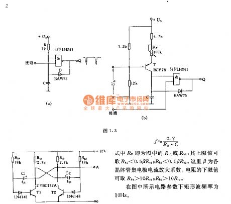
The two parts' component parameters and models of the circuit are corresponding to simultaneously obtain a rectangular wave with duty ratio of 1:1, its frequency f = 0.7/RB • C. RB is Rb1 or Rb2 in the figure, and its upper limit value Rb1 < 0.5βRC1 ; Rb2 < 0.5βRC2, here β is the transistor collector current amplification factor. The lower limit value of the resistor is Rb1 > 10βRC1 ; Rb2 > 10βRC2, the of rectangular wave frequency under circuit parameters shown in figure is 10Hz.
(View)
View full Circuit Diagram | Comments | Reading(1926)
Trapezoidal wave generator ( Figure 1.7 ) circuit
Published:2012/8/21 20:12:00 Author:Ecco | Keyword: Trapezoidal wave, generator

Trapezoidal wave's time t1 ~ t4 can be independently adjusted. Time t1 can be coarse tuned by capacitor C1 and fine tuned by potentiometer Rp. T2 is coarse and fine tuned by C2 and R2. t1 + t2 determines the period or frequency. t3 is changed by the potentiometer RP3, and its value is calculated according to t3 = CRE • UA / UE. RE is PNP transistor emitter resistance, UE is emitter voltage drop, UA is the magnitude of output voltage.
(View)
View full Circuit Diagram | Comments | Reading(1546)
Oscillator for electronic musical instruments
Published:2012/8/21 3:48:00 Author:Ecco | Keyword: Oscillator , electronic musical instruments
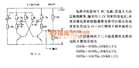
The circuit comprises two RC circuits, the value can determine the oscillation frequency. The output rectangular wave voltage is approximately 7.5V. It uses metallized polycarbonate film capacitor to guarantee that the frequency deviation is less than 0.5% in the temperature range of 10 ~ 40 ℃. The R values of 12 oscillators in an octave process are selecting as below.
(View)
View full Circuit Diagram | Comments | Reading(1008)
Common-base quartz controlled frequency capacitance feedback oscillator
Published:2012/8/21 20:02:00 Author:Ecco | Keyword: Common-base , quartz , controlled frequency , capacitance feedback , oscillator
View full Circuit Diagram | Comments | Reading(1019)
The LC oscillator circuit for electronic cello
Published:2012/8/21 20:00:00 Author:Ecco | Keyword: LC oscillator , electronic cello
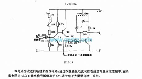
This circuit is the improved hartley oscillator circuit, changing the base current can adjust the frequency in a given range. The output signal amplitude is higher than 6V in 6kΩ load resistance,and it is suitable for electronic cello circuits.
(View)
View full Circuit Diagram | Comments | Reading(1929)
The circuit of photoelectric controlling
Published:2012/8/21 3:38:00 Author:Ecco | Keyword: Photoelectric controlling
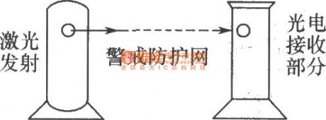
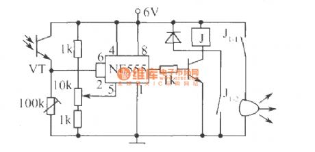
Photoelectric control circuit is shown as the figure. NE555 circuit is the core component of the circuit, when photodiode VT receives laser irradiation and turned on, the pin 6 threshold of time-base circuit and pin 2 of trigger end rise above 4V, so the pin 3 outputs low, relay does not pull. When the laser is blocked, VT is turned off, pin 2 and pin 6 become low, pin 3 outputs high, relay is energized, J1-2 pulls to get self-locking, J1-1 pulls to make bells issue alarm sound. The installation can be made according to the following figure, the transceiver end needs to be made as removable or fixed Alert Network. if someone blocks laser path, the alarm emits sound. It can be widely used in warehouse, station temporary heap objects, large area of orchards and other protection applications.
(View)
View full Circuit Diagram | Comments | Reading(989)
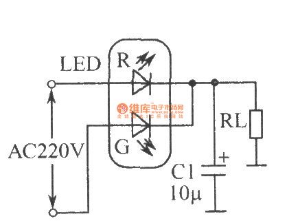
The circuit of LED full-wave rectifier
Published:2012/8/21 3:39:00 Author:Ecco | Keyword: LED, full-wave rectifier
View full Circuit Diagram | Comments | Reading(1158)
Automobile AM radio circuit
Published:2012/8/20 22:29:00 Author:Ecco | Keyword: Automobile, AM radio
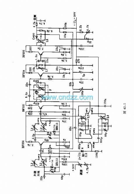
This circuit shows the high and mid part of car radio, and the medium wave band I is 520 ~ 950kHz, Poland II is 900 ~ 1640kHz. Loop tuning uses tunable diode BB113.Main coil data:L1: 122 turns; L2: 122 turns ; L3: 68 turns ; L5: 96 turns ( coupling coil with 7 turns ); L6: 64 turns ( coupling coil with 5 turns) . L1 ~ L6 use 8 × 0.03 copper.L7: 90 turns, 6 × 0.04 copper.L8: 120 turns ( coupling coil with 60 turns ), 8 × 0.03 copper.F: 95 turns ( coupling coil with 5 turns ), 8 × 0.04 copper.
(View)
View full Circuit Diagram | Comments | Reading(2454)
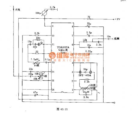
FM wireless headphone circuit
Published:2012/8/20 22:08:00 Author:Ecco | Keyword: FM , wireless headphone
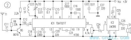
Figure 1 is a transmitting circuit of wireless headset, the audio signal obtained by television headphone jack bu passing stereo headphone plug is amplified by BG2, then it is amplitude limited by limiter circuit composed of D1, D2, C2, C3 and sent to high frequency oscillator composed of BG2; the modulated FM signal is coupled by C7 and emitted by antenna. Figure 2 is a receiving circuit which uses dedicated FM receiver module IC1 TDA7021T as the core. The demodulated audio signal is output from the foot sent to IC2 LM386 for power amplification and promote the headphones sound. Transistor BG 9018 form the high - frequency amplifier stage in order to improve the reception sensitivity.
(View)
View full Circuit Diagram | Comments | Reading(4445)
The shortwave tuner circuit with browband range in 5.8 ~ 10.5MHz
Published:2012/8/20 22:42:00 Author:Ecco | Keyword: shortwave tuner , browband range , 5.8 ~ 10.5MHz
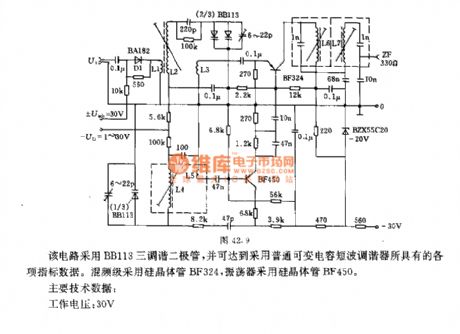
This circuit uses BB113 three tunable diode to reach the indications and data with the ordinary variable capacitance shortwave tuner. The mixer stage uses silicon transistor BF324, and oscillator uses silicon transistor BF450.Main technical data: Operating voltage : 30VConsumption current : 20mATuning voltage : 0.5 ~ 30VCoil data : L1: antenna coupling coil 60Ω, 8 turns, 0.12mm copper enameled wire; L1 and L2 have 5mm interval; L2 : input loop, 26 turns, 12 × 0.05 copper stranded wire; L2 and L3 have 3mm interval; L3: high frequency coupling coil, 2 turns of 0.25mm copper enameled wire.
(View)
View full Circuit Diagram | Comments | Reading(1548)
Power line carrier amplifier circuit
Published:2012/8/21 1:15:00 Author:Ecco | Keyword: Power line carrier , amplifier
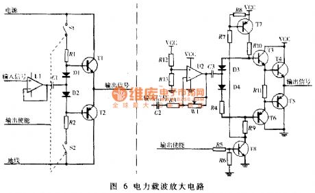
View full Circuit Diagram | Comments | Reading(2869)
Radio circuit with quartz crystal oscillator
Published:2012/8/21 1:07:00 Author:Ecco | Keyword: Radio , quartz crystal, oscillator
The circuit's frequency can be to 27MHz. Intermediate frequency is 455kHz. In order to increase the receive frequency, it uses the pre-stage of the field effect transistor.
(View)
View full Circuit Diagram | Comments | Reading(1839)
Medium-wave AM radio circuit
Published:2012/8/19 21:28:00 Author:Ecco | Keyword: Medium-wave , AM , radio
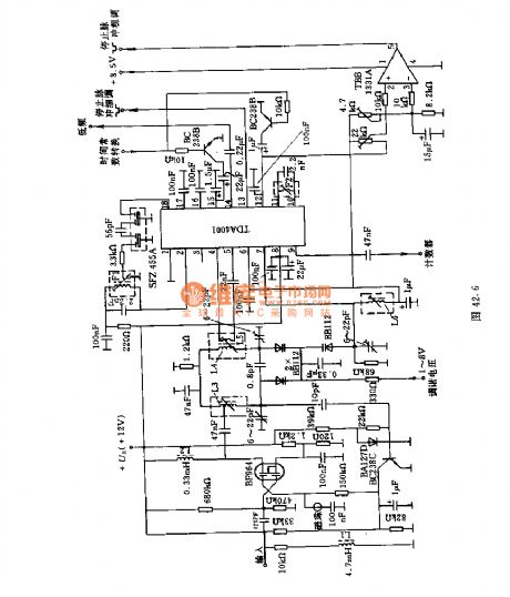
This circuit uses a FET for the preamp, and input signal is applied to the gate. In the drain loops, two loops have band-pass filter, and they use two tunable diodes for tuning. The resonant circuit determines the frequency, which is connected to pin 10 and 11 of IC.
(View)
View full Circuit Diagram | Comments | Reading(1875)
The homemade USB port ISP (2313 Analog USB)
Published:2012/8/21 1:11:00 Author:Ecco | Keyword: homemade , USB port , ISP, Analog USB
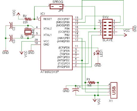
Many laptop have no serial or parallel ports. In this case, only use the USB port ISP. The production doesn't use a real USB chip, but it uses 2313 analog USB timing.
(View)
View full Circuit Diagram | Comments | Reading(4592)
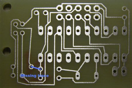
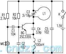
Highly sensitive wireless Snoop device circuit
Published:2012/8/20 23:05:00 Author:Ecco | Keyword: Highly sensitive , wireless , Snoop device
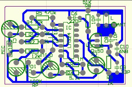
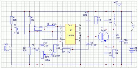
The circuit is shown in the figure, it is composed of highly sensitive microphone amplifier and wireless transmitter unit, and the amplifier consisits of two op amps in quad op amp integrated circuit LM324. When the electret microphone MIC picks up weak sound signal, it will generate a signal voltage across the MIC, then the signal is amplified by pin 3 of the first stage operational amplifier after being coupled by capacitor C1, its amplification gain is more than 20 decibels, after the first-stage coupling, it is output from pin 1 and coupled by capacitor C3, then potentiometer RP control it for the second-stage amplifier by pin 5, then weak voice signal is amplified to have sufficient magnitude and sent to high - frequency transmitting circuit by coupling with C5.
(View)
View full Circuit Diagram | Comments | Reading(4240)
The application circuit of TDA7088 FM integrated circuit
Published:2012/8/20 21:49:00 Author:Ecco | Keyword: application , FM , integrated circuit
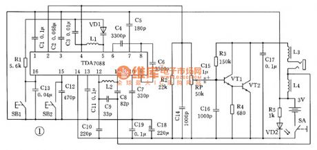
Figure 1 is the automatically search schematic diagram of FM radio. Its core component is a TDA7088 integrated circuit which includes FM radio receiver, antenna, oscillator, mixer, AFC ( frequency automatic control) circuit, intermediate frequency amplifier ( IF frequency is 70kHz), IF limiter, IF filter, frequency discriminator, low frequency squelch circuit and audio output; it also specifically sets search tuning circuit, signal detection circuit and frequency locked loop. It can use a varactor diode to replace the variable capacitor is, which is a special kind of diodes. The PN junction capacitance is changed with the bias voltage ( reverse voltage) on PN junction.
(View)
View full Circuit Diagram | Comments | Reading(4635)
The production circuit of three-tube FM wireless microphone
Published:2012/8/20 20:11:00 Author:Ecco | Keyword: three-tube , FM, wireless microphone
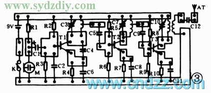
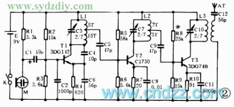
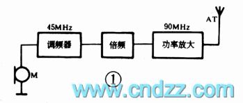
The microphone uses the direct FM mode with the center frequency in 90MHz, transmit power is about 0.5W, and the largest frequency offset is 50kHz, and the transmitting distance is not less than 50 meters. The block diagram and schematic diagram are shown in Figure 1,2. The audio signal generated by the electret microphone acts on the emission junction of the modulator T1 as the modulation voltage. The size of voltage directly changes the junction capacitance of the transistor emitter junction, and the junction capacitance is a part of the circuit parameters; fo is about 45MHz, and the output frequency can be up to 90MHz after frequency doubling, the FM signal is emitted by an antenna after being amplified by high-frequency amplifier.
(View)
View full Circuit Diagram | Comments | Reading(1837)
Simple long-distance wireless FM microphone circuit
Published:2012/8/21 1:29:00 Author:Ecco | Keyword: Simple, long-distance, wireless , FM microphone
The the loop antenna L1 for emission also serves as the oscillation coil, the high-frequency current flowing in antenna is synchronized resonance with the oscillation frequency, so it is always in the best emission state. Accoring to practice, launching distance is about 100 ~ 150m in empty mine. In contrast, in the case of equal working voltage, current and emission frequency, L1 is replaced by ordinary spiral coil, the oscillation transistor collector is connected to a 5pF capacitor and 0.8m Rod antenna for emission experiments, the two the transmitting distancea are almost equal. So it proves that the concealed loop antenna( it doubles the oscillator coil) has high emission efficiency.
(View)
View full Circuit Diagram | Comments | Reading(2936)
FM wireless microphone circuit with voltage regulator circuit
Published:2012/8/21 1:53:00 Author:Ecco | Keyword: FM , wireless microphone , voltage regulator
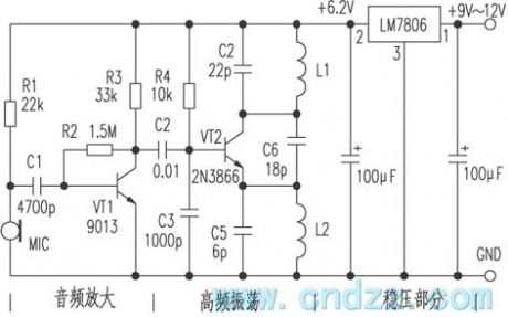
The circuit consists of three parts: 1 . Audio amplifier section; 2 . High-frequency oscillation part; 3 . Regulators parts. The signal is sent into a base of the transistor VT1 from the microphone MIC, then it is coupled to the base of high-frequency oscillation circuit VT2 by C2 after being amplified by VT1, then it is emitted by antenna. The working frequency of this circuit is between 85 ~ 104MHz. MIC selects high-sensitivity electret microphone, VT1 uses 9013H with β ≥ 125. VT2 is 2N3866 with β ≥ 90, L1, L2 use∮ 0.71mm enameled wires with four turns and 10 turns around ordinary pen core, C4, C5, C6 use ceramic capacitors, error is ± 5 % . The three-terminal regulator uses the LM7806 power supply with 9V battery, and the circuit board can be made by yourself.
(View)
View full Circuit Diagram | Comments | Reading(3021)
| Pages:365/2234 At 20361362363364365366367368369370371372373374375376377378379380Under 20 |
Circuit Categories
power supply circuit
Amplifier Circuit
Basic Circuit
LED and Light Circuit
Sensor Circuit
Signal Processing
Electrical Equipment Circuit
Control Circuit
Remote Control Circuit
A/D-D/A Converter Circuit
Audio Circuit
Measuring and Test Circuit
Communication Circuit
Computer-Related Circuit
555 Circuit
Automotive Circuit
Repairing Circuit