
Circuit Diagram
Index 371
Thyristor double-tone dimmer circuit (1)
Published:2012/8/1 2:12:00 Author:Ecco | Keyword: Thyristor, double-tone dimmer
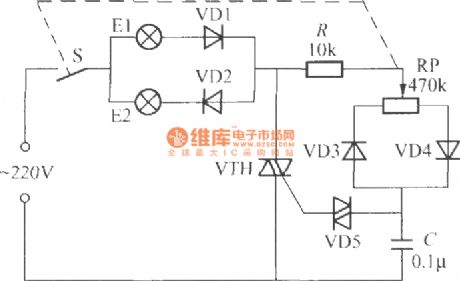
In the circuirshown as the figure, VTH canuse TLC221B or MAC94A4 bidirectional thyristor, VD1 ~~ VD4select 1N4007 silicon rectifier diodes, VD5 is 2CTS bidirectional trigger diode withrequiring the transition voltage being30 ~ 39V.
(View)
View full Circuit Diagram | Comments | Reading(1727)
Thyristor double-tone dimmer circuit (2)
Published:2012/8/1 2:10:00 Author:Ecco | Keyword: Thyristor, double-tone dimmer
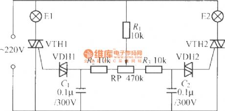
VTH1, VTH2 can use TLC221B MAC94A4, MAC97A6 small plastic bi-directional triode thyristors. VDH1, VDH2 use 2CTS bi-directional trigger diodes with requiring the transition voltagebeing 30 ~ 39V. The power of E1, E2 should be less 60W or 60W.
(View)
View full Circuit Diagram | Comments | Reading(3370)
Three-way blinking light string circuit (5)
Published:2012/8/1 2:32:00 Author:Ecco | Keyword: Three-way , blinking, light string
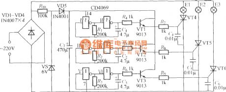
As shown in the figure, the three-way flashing light string controlleris made by a digital integrated circuit, and shiningchange of light string is random, unpredictable, very interesting.
(View)
View full Circuit Diagram | Comments | Reading(1452)
Neon patterns controlling circuit ( DNL9100 )
Published:2012/8/1 2:37:00 Author:Ecco | Keyword: Neon patterns , controlling circuit
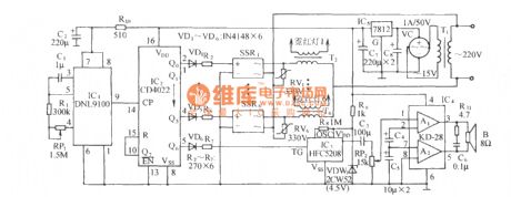
The circuit is shown as the figure. It includes the oscillation pulse signal source, octal counting / pulse divider, AC solid state relay driver circuit, neon high-voltage transformerand power supply, etc. .
(View)
View full Circuit Diagram | Comments | Reading(1157)
Hair dryer circuit
Published:2012/8/1 2:35:00 Author:Ecco | Keyword: Hair dryer
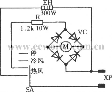
XP is thepower plug. EH is the 300W heating wire. R is the dropping resistor. VC is the bridge rectifier, and SA is thegear switch.
(View)
View full Circuit Diagram | Comments | Reading(8167)
Two-speed fan control circuit
Published:2012/8/1 2:06:00 Author:Ecco | Keyword: Two-speed fan , control circuit
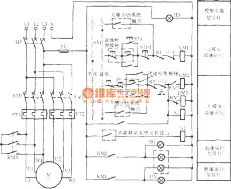
The two-speed exhausting fancomposed ofpole-changing adjustable speed motor is widely used in high-rise and underground buildings. Usually it runs at low speed; when the fireisbroke out, itcan be swicthed by manual, fire -place control systems or BAS system to high-speed operationautomatically to be used as exhausting fan. The circuit is shown as the chart.
(View)
View full Circuit Diagram | Comments | Reading(4658)
Three-controller light switch circuit
Published:2012/8/1 2:30:00 Author:Ecco | Keyword: Three-controller, light switch
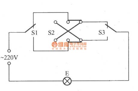
Three-controller switchmeans the circuit can independently control the same lamp's lighting or extinguishing in three different places, and the circuit is shown as the figure. In the figure S1 , S3, 1 × 2 are single - pole double-throw switches, and S2 uses the 2 × 2 DPDT switch.
(View)
View full Circuit Diagram | Comments | Reading(2275)
Thermal pyroelectric infrared sensing automatic light circuit (1)
Published:2012/8/1 2:20:00 Author:Ecco | Keyword: Thermal, pyroelectric, infrared , sensing , automatic light
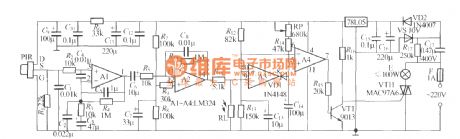
As shown in the figure, the circuit is a pyroelectric infrared sensing automatic light which can be used for stairs walkways , bathrooms and other occasions. The lights can be turned on when people come, turning off when people leave, and the lights are automatically locked during the day, so the lamps will not be lit. The PIR can use P228 pyroelectric infrared sensor. In order to improve its sensitivity, it is best for their installation of the Fresnel lens, and the focus of the lens should be located in the sensingwindow of sensor. RP is the circuit delay time adjustment potentiometer, and it can also use an ordinary fixed resistor.
(View)
View full Circuit Diagram | Comments | Reading(1600)
Thermal pyroelectric infrared sensing automatic light circuit (10)
Published:2012/8/1 2:16:00 Author:Ecco | Keyword: Thermal, pyroelectric , infrared , sensing , automatic light

As shown in the figure, the circuit usesthe YB- 28 pyroelectric infrared sensor modules to make sensing automatic lights, and the circuit is very simple. Itcan easily achievethe effect of turing onthe lights when people come, off when leave.
(View)
View full Circuit Diagram | Comments | Reading(1658)
Thermal pyroelectric infrared sensing automatic light circuit (2)
Published:2012/8/1 2:26:00 Author:Ecco | Keyword: Thermal , pyroelectric , infrared , sensing , automatic light
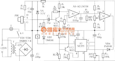
The figure shows a the pyroelectric infrared sensing automatic lights circuit with good performance. It uses relay to control light, soit can control theautomatically turning on of fluorescent lamps and automaticallycontrolling of incandescent lighting.
(View)
View full Circuit Diagram | Comments | Reading(1547)
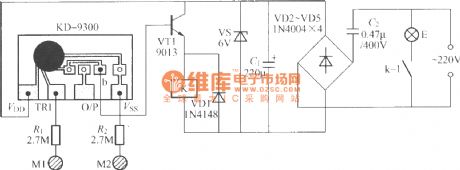
Double-key touching lamp switch circuit (2)
Published:2012/7/27 1:21:00 Author:Ecco | Keyword: Double-key, touching lamp , switch

As shown in the figure, it is a double-key touching lamp switch circuit compoased of homemade optocoupler and thyristor rectifier circuit. V1 ~ V3can useNH-416, NHO-4L and other small neon bubbles; RL1 , RL2can selectMG45 photosensitive resistor. VTH1, VTH2 can use small plastic MAC94A4 or MAC97A6 bidirectional thyristor, and the power of controlled lamp E should be limited to be lower than 100W.
(View)
View full Circuit Diagram | Comments | Reading(1660)
Double-key touching lamp switch circuit (4)
Published:2012/7/27 1:18:00 Author:Ecco | Keyword: Double-key , touching lamp , switch
In the figure, K can use JZC- 22F DC12V small medium power electromagnetic relay, and other components have no special requirements.
(View)
View full Circuit Diagram | Comments | Reading(1424)
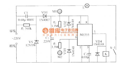
Double-key touching lamp switch circuit (8)
Published:2012/7/27 1:08:00 Author:Ecco | Keyword: Double-key, touching lamp , switch
As shownin the figure, the circuitis made byan ordinary music doorbell chip. K can use JZC- 22F DC12V small medium power electromagnetic relay, and other components have no special requirements.
(View)
View full Circuit Diagram | Comments | Reading(1284)
Double-key touching lamp switch circuit (9)
Published:2012/7/27 1:15:00 Author:Ecco | Keyword: Double-key, touching lamp , switch
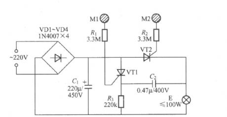
In the Figure , VT1, VT2 can use 2N6565, BT169 small plastic unidirectional thyristor. In this circuit, it you choose the appropriate resistance of R3, whne the lights are turning off, after the manpower leave the M1, VT1 can be turned off automatically because the anode currentflowing through the the VT1is too small, thereforeto save power consumption of the circuit.
(View)
View full Circuit Diagram | Comments | Reading(2749)
2D lamp controller
Published:2012/7/25 2:59:00 Author:Ecco | Keyword: 2D lamp , controller
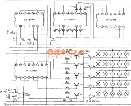
As shown in the figure, the circuit is mainly composed of the NAND gate IC1 (CD4096), counting / timing distribution circuit IC2 (CD4017), analog electronic switch IC3 (CD4066) and D trigger IC4 (CD40174). The lamp controller can control five groups of Lanterns to be lit and extinguished progressively. If a certain number of lanterns are connected in combination, you can create a scene with color change on the plane. It is more rich and colorful than usually control the flowing of the color in a line.
(View)
View full Circuit Diagram | Comments | Reading(2342)
Typical application circuit of nRF401 single - chip RF transceiver
Published:2012/7/25 3:10:00 Author:Ecco | Keyword: Typical application, single - chip, RF transceiver

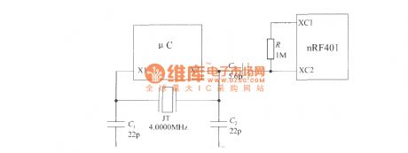
The nRF401 typical application circuit is shown as the figure. The UDD uses a +3 V power supply. The crystal oscillator circuit is composed of R1 , JT , C1 and C2; C3 , C4 and R2 form the loop filter. R3 can be used to set resistance for the power. C5 is the power decoupling capacitor, C6 and C7 are noise canceling capacitors. DIN and DOUT side are respectively connected the MCU's TXD port ( serial output ) , RXD port( serial input ). In order to simplify the circuit, nRF401 can connect with μC to be used as a crystal oscillator circuit, and it is shown as below. X1 and X2 are μC's crystal input and output ports, and the generating crystal frequency is sent directly to the XC2 side of nRF401.
(View)
View full Circuit Diagram | Comments | Reading(1375)
The converter IC circuit diagram
Published:2012/7/25 3:25:00 Author:Ecco | Keyword: converter IC
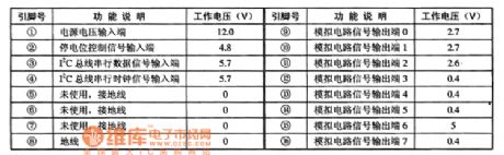
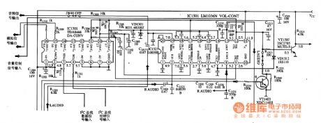
TDA8444is the D / A ( digital / analog ) converter IC produced by Philips, and it is used to convert digital signals to analog signals.1. pin functions and dataTDA8444 IC uses 16-pin double-row package, andpin functions and data are shown in Table 1 .
2. Typical application circuitTDA8444 and LM1036Nare matched byCPU to control the tone, volume , two-channel electronic balance. The the typical application circuit isshown in Figure 1.
(View)
View full Circuit Diagram | Comments | Reading(2217)
TDA8755 D/A converter IC circuit diagram
Published:2012/7/25 3:21:00 Author:Ecco | Keyword: D/A converter , IC
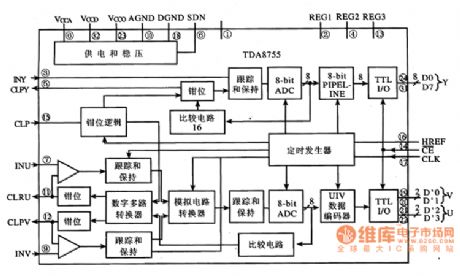
TDA8755 is the D / A ( digital / analog ) converter IC produced by philips company. It is suitable for A / D converter occasions such as the all applications included TV ( rear projection , LCD ), DVD players, instrumentation and so on.
(1) Functions and Features
TDA8755 integrated circuit includes a digital multi-channel converter, analog circuit converter, ADC circuit, digital encoder, clamping logic circuit, ADC interface circuit, tracking and maintaining circuit, timing generator, comparator circuit, power supply and regulator circuit and other auxiliary functions circuit. Its block diagram is shown in Figure 1.
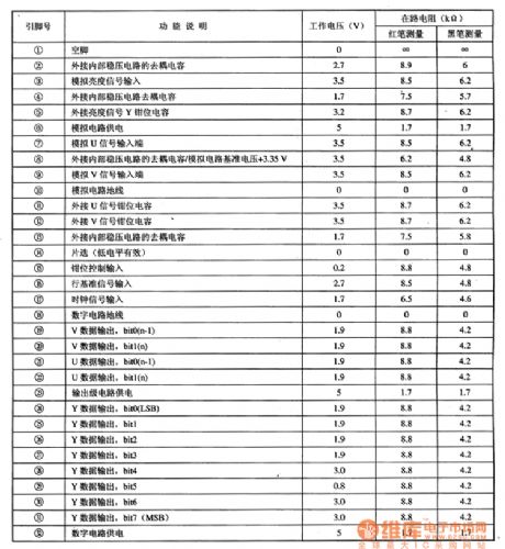
(2) pin functions and dataThe TDA8755 IC uses 32-pin double-row hundred plug-in package,and pin functions and data are shown in Table 1 . (View)
View full Circuit Diagram | Comments | Reading(1825)
555 dual astable multivibrator circuit diagram
Published:2012/7/23 3:10:00 Author:Ecco | Keyword: 555, dual astable multivibrator


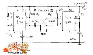
The circuit includes two synchronized multivibrators which are composed ofone pair of 555time base circuits. The circuit can output two synchronized pulse signals ,and the spacing and frequency can be changed by adjusting the time constant. The circuit is flexible and convenient.
When C1=C2=C, the oscillation frequency
The ducy cycle depends on the value of R1 and R2, and it can reach 5% ~ 95%.
(View)
View full Circuit Diagram | Comments | Reading(3557)
MAX264 filter circuit diagram
Published:2012/7/23 3:01:00 Author:Ecco | Keyword: filter
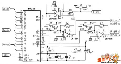
The system design uses a pin programmable filter MAX264 to realize low-pass or high pass filter, and the circuit is shown in the figure ( Attenuation amplification network). The circuit design uses unipolar input mode, and its input voltage range is 0 V to 5 V. When people adjust circuit, the signal should be adjusted to the input range. Conditioning process: the signal first passes the attenuation network to make the peak - the peak be -2.5 V ~ +2.5 V, then the adder adjusts the signal to the range of 0 V ~~ 5 V, after filtering , the subtractor turns signal into - 2.5 V ~ +2.5 V, and zoom network is used to compensate balance attenuation, then the circuit outputs the rms to converter circuit.
(View)
View full Circuit Diagram | Comments | Reading(1317)
| Pages:371/2234 At 20361362363364365366367368369370371372373374375376377378379380Under 20 |
Circuit Categories
power supply circuit
Amplifier Circuit
Basic Circuit
LED and Light Circuit
Sensor Circuit
Signal Processing
Electrical Equipment Circuit
Control Circuit
Remote Control Circuit
A/D-D/A Converter Circuit
Audio Circuit
Measuring and Test Circuit
Communication Circuit
Computer-Related Circuit
555 Circuit
Automotive Circuit
Repairing Circuit