
Circuit Diagram
Index 378
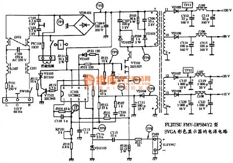
The power supply circuit diagram of FUJITSU FMV-DPS84Y2 SGVA color dispaly
Published:2011/11/10 2:08:00 Author:May | Keyword: power supply, FUJITSU, color dispaly , SGVA
View full Circuit Diagram | Comments | Reading(2117)
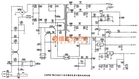
The power supply circuit diagram of CASPER TM-5154H SVGA multiple frequency color display
Published:2011/11/10 2:10:00 Author:May | Keyword: power supply, CASPER, SVGA, multiple frequency, color display
View full Circuit Diagram | Comments | Reading(1455)
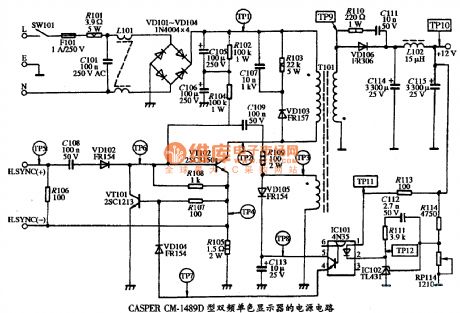
The power supply circuit diagram of CASPER CM-1489 dual frequency monochrome display
Published:2011/11/10 2:10:00 Author:May | Keyword: power supply, CASPER, dual frequency, monochrome display
View full Circuit Diagram | Comments | Reading(1456)
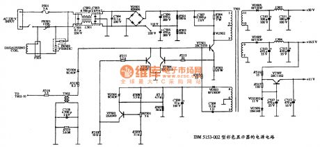
The power supply circuit diagram of IBM 5153-002 color display
Published:2011/11/10 2:11:00 Author:May | Keyword: power supply, color display, IBM
View full Circuit Diagram | Comments | Reading(3573)
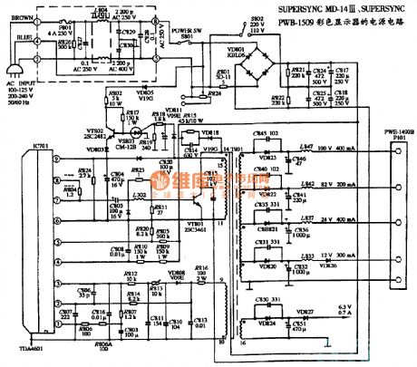
The power supply circuit diagram of SUPERSYNC MD-14III, SUPERSYNC PWB-1509 type color display
Published:2011/11/10 2:14:00 Author:May | Keyword: power supply, color display, SUPERSYNC
View full Circuit Diagram | Comments | Reading(1042)
The power supply circuit diagram of three kinds color display
Published:2011/11/10 2:13:00 Author:May | Keyword: power supply, color display, SUPERSYNC
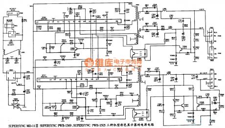
The power supply circuit diagram of SUPERSYNC MD-11III, SUPERSYNC PWB-1369, SUPERSYNC PWB-1505 color display (View)
View full Circuit Diagram | Comments | Reading(993)
The power supply circuit diagram of six color displays
Published:2011/11/10 2:20:00 Author:May | Keyword: power supply, color display, SUPERSYNC
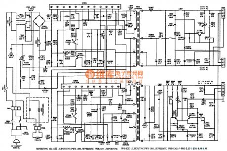
The power supply circuit diagram of SUPERSYNC MD-10III, SUPERYNC PWB-1290, SUPERSYNC PWB1291, SUPERSYNC PWB-1293, SUPERSYNC PWB-1361, SUPERSYNC PWB-1362 color displays
(View)
View full Circuit Diagram | Comments | Reading(1268)
Blocking AC power supply with TDA4600
Published:2011/11/23 2:04:00 Author:May | Keyword: Blocking AC, power supply
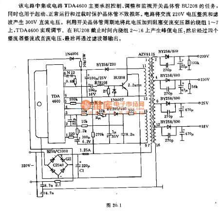
Integrated circuit TDA4600 in this circuit mainly has the task of controlling, adjusting and overseeing switching BU208. Meanwhile it isalso used to protect transistor from damaging in starting, normal operating and over load. AC 220V voltage is rectified and filtered by the circuit. And then it can generate 300V DC voltage. It can periodically add this voltage to winding 1~7 of blocking AC transformer by utilizing switching transistor. And TDA4600 is achieved adjusting. In the period of BU208 cut off, it can generate 3 peak value voltage on winding 2~16, then it is rectified to DC voltage by four rectifiers, finally, it is output by filter. (View)
View full Circuit Diagram | Comments | Reading(2003)
5V/10A 100kh choking transducer XDUCER using SIPMOS transistor
Published:2011/11/22 1:42:00 Author:May | Keyword: 5V/10A, 100kh , choking transducer XDUCER , SIPMOS transistor
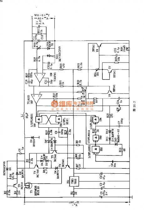
This circuit can convert 24V DC voltage to output DC voltage with low voltage. Its switching transistor uses SIPMOS tube BUZ23, andits featuresare thatlimiting frequency is much higher and needed controlling power is very small. In order to have higher switching frequency, the circuit adopts thechoke with small inductance value and filter capacitors C1~C3 with small capacitance.
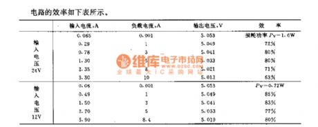
The efficiency of this circuit is shown in the following table.
(View)
View full Circuit Diagram | Comments | Reading(1113)
5V/10A 20kHz blocking communication device using SIPMOS transistor
Published:2011/11/23 1:54:00 Author:May | Keyword: 5V/10A 20kHz, blocking communication device, SIPMOS transistor
This circuit is convertor which can change input DC voltage (+20~+30V) to lower DC output voltage (+5V). Integrated circuit TDB0555B is time base circuit which can generate 20kHz square wave. The timing time of output (pin 3) is between 10~40μs. Fixed bias can make T1 to break over. Square wave voltage output by TDB0555B is differential to triangle wave voltage by R4, C5 and R6+R7. It also can make T1 cut off. So T1's output is square wave. Then the transformer can output AC and DC voltage after rectifying and filtering before passing opposite phase grade, drive grade and power amplifier grade.Main technical data: input voltage: +20~30V (rated value is 24V);output voltage: +5V;output current: 10A;network voltage adjustment rate: ±0.5%;load voltage adjustment rate: ±2%;efficiency: 78% (when the input voltage is 24V) (View)
View full Circuit Diagram | Comments | Reading(732)
SIPMOS transistor control circuit using optical isolation
Published:2011/11/23 2:20:00 Author:May | Keyword: SIPMOS transistor, control, optical isolation
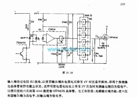
When TDA4700's output transistor is breaking over, optoelectronic isolator is breaking over. R1 is used for limitting the current, its value's sending and getting must make light coupled input end have about 4mA current. Diode D1 is used for limitting reverse over voltage when it is cut off. The input end of light coupling output gate circuit is connecting with ground through resistor R2 in order to make its output endbe open circuit when the power supply voltage drops to 4V. That is two push pull circuits's output transistor keeps on the cutting off state. It can make light coupling output to be low level when power supply voltage increases to about 3V in order to make back connecting six inverter 4096to control SIPMOS transistor. When it is working, light coupling end is open, it can make six inverter output end be in high level, but its output end is in low level. (View)
View full Circuit Diagram | Comments | Reading(1336)
Humidity indicator circuit
Published:2011/11/23 2:10:00 Author:May | Keyword: Humidity indicator
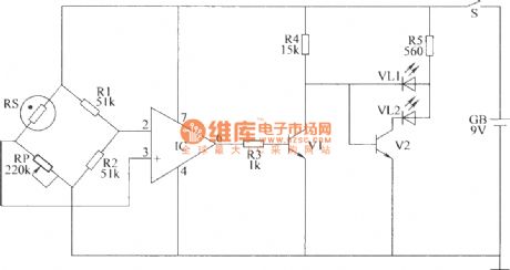
For the purpose of raising early and better seeding, in the village, people always use plastic film to make up simple raise seed shed in the ground. The disadvantage of this shed is the humidity in the shed is often too large, and it affects the normal growth of seeds. This example describes a simple seedling shed moisture indicator, which uses LED to indicate the size of the humidity of the greenhouse seedlings, and it is easy to use. This humidity indicator circuit consists of moisture detection amplifier and LED indication circuit, and it isshown in the diagram.
You can set the desired humidity alert by adjusting the resistance of RP.
Component selection:
R1 ~ R5 use 1/4W carbon film resistor or metal film resistors;
RP is organic, solid potentiometer or variable resistor. RS is made by 3DG6 transistors with the value greater than 100.
VL1 and VL2 choose light-emitting diodes φ5mm. V1 and V2 select 3DG6 or S9013 silicon NPN transistor. IC chooses μA741 or 5G24-type IC op amp IC. GB chooses 9V laminated battery. S chooses small single pole toggle switch. (View)
View full Circuit Diagram | Comments | Reading(1549)
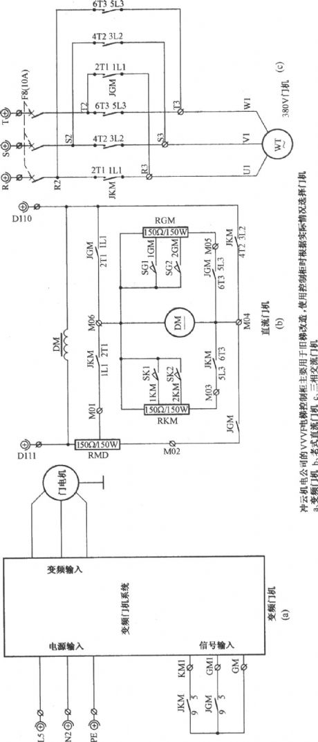
Beijing chongyun elevator door driver circuit
Published:2011/8/24 2:58:00 Author:Jessie | Keyword: Beijing chongyun , elevator door driver
View full Circuit Diagram | Comments | Reading(1344)
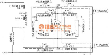
Beijing tujie Elevator door driver circuit
Published:2011/8/24 2:57:00 Author:Jessie | Keyword: Beijing tujie , Elevator door driver
View full Circuit Diagram | Comments | Reading(1229)
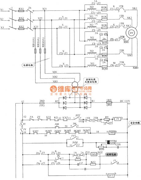
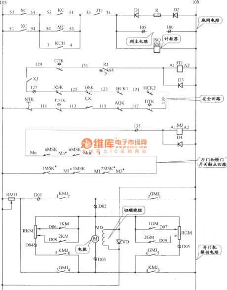
APM-81 The main circuit of elevator, safety loop and dlectrical circuit
Published:2011/8/26 4:06:00 Author:Jessie | Keyword: elevator, safety loop, dlectrical
View full Circuit Diagram | Comments | Reading(2516)
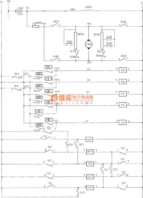
APM-81 elevator door driver and mun circuit
Published:2011/8/26 3:50:00 Author:Jessie | Keyword: elevator door driver , mun
View full Circuit Diagram | Comments | Reading(1310)
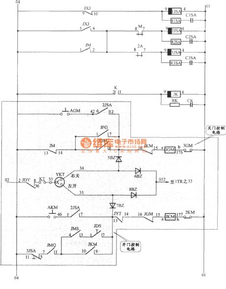
APM-81 elevator door driver control circuit
Published:2011/8/24 2:43:00 Author:Jessie | Keyword: elevator, door driver control
View full Circuit Diagram | Comments | Reading(1285)
Rice seeding bed high temperature alarm circuit
Published:2011/12/5 1:08:00 Author:May | Keyword: Rice seeding bed, high temperature alarm
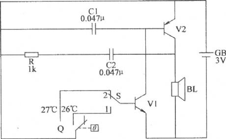
This rice seeding bed high temperature alarm circuit consists of electric hot thermometer Q, switch S, transistors V1, V2, resistor R, capacitors C1, C2, GB speaker BL and battery GB(V1, V2, and C1, C2, R, BL make up complementary oscillator circuit), and it isshown in the diagram. Component selection: R chooses 1/4W metal film resistor or carbon film resistor. C1 or C2choose polyester capacitors or monolithic capacitors. V1chooses 3DG6 or S9013 NPN silicon transistor; V2chooses 3AX81 germanium PNP transistors. BLchooses chose 0.25W, 812 electric loudspeaker. Qchooses fixed electric hot mercury thermometer. Schooses double-pole toggle switch. GBchooses two AA batteries. (View)
View full Circuit Diagram | Comments | Reading(1454)
Double-limit temperature alarm circuit 2
Published:2011/11/23 2:07:00 Author:May | Keyword: Double-limit, temperature alarm
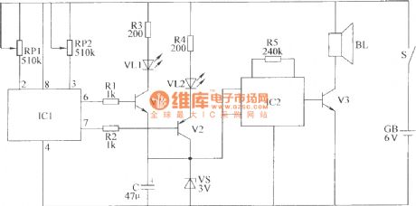
This double-limit temperature alarm circuit consists of temperature detection circuit control circuit, temperature indicating circuit and sound alarm circuit, as shown in the diagram.Component selection: R1 ~ R5 choose 1/4W carbon film resistor or metal film resistors. RP1 and RP2 chose small organic solid potentiometer. C choses electrolytic capacitors voltage is 10V. VL1 and VL2 are chose high-brightness light-emitting diodes φ3mm, VL1 is red, VL2 is green. VS chooses 1/2W, 3V voltage silicon diodes. V1 and V3 choose S9013 or C8050 silicon NPN transistor; V2 chooses S9015 or C8550 silicon PNP transistors. IC1 chooses TC602 temperature sensor integrated circuit; IC2 chooses S9015 or C8550 type silicon PNP transistor.BL chooses 0.25W, 8Ω micro-electric speaker. S chooses small single pole toggle switch. GB chopses 6V battery stack. (View)
View full Circuit Diagram | Comments | Reading(1296)
Shenyang sanyo AC two-speed elevator brake, gantry crane and security loop circuit
Published:2011/8/28 22:10:00 Author:Jessie | Keyword: Shenyang sanyo , AC two-speed, elevator brake, gantry crane , security loop
View full Circuit Diagram | Comments | Reading(1526)
| Pages:378/2234 At 20361362363364365366367368369370371372373374375376377378379380Under 20 |
Circuit Categories
power supply circuit
Amplifier Circuit
Basic Circuit
LED and Light Circuit
Sensor Circuit
Signal Processing
Electrical Equipment Circuit
Control Circuit
Remote Control Circuit
A/D-D/A Converter Circuit
Audio Circuit
Measuring and Test Circuit
Communication Circuit
Computer-Related Circuit
555 Circuit
Automotive Circuit
Repairing Circuit