
Circuit Diagram
Index 374
4096 bits CCDP drive circuit
Published:2011/4/15 5:39:00 Author:May | Keyword: 4096 bits, CCDP drive
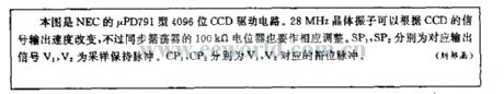
This diagram is NEC μPD791 type 4096 bits CCD drive circuit. 28MHz crystal oscillator can change according to CCD signal output speed. But 100kΩ potentiometer of lock-in oscillator should be adjusted accordingly. SP1, SP2 separately is corresponding signal. V1, V2 is sample hold pulse. CP1, CP2 separately is V1, V2 corresponding phase impulse. (View)
View full Circuit Diagram | Comments | Reading(1362)
2-10 system decoding circuit
Published:2011/12/1 20:30:00 Author:May | Keyword: 2-10 system, decoding
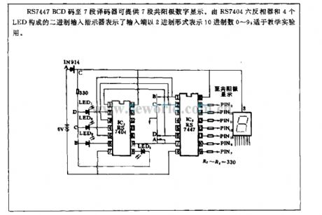
RS7447 BCD code to seven-segment decoder can provide seven segment common anode digisplay. Binary system input pointer consists of RS7404 six inverter and four LED. It shows that input end uses binary system form to express ten's digit. It is suited to teach experiment.
(View)
View full Circuit Diagram | Comments | Reading(2244)
Test probe circuit
Published:2011/11/10 1:35:00 Author:May | Keyword: Test probe
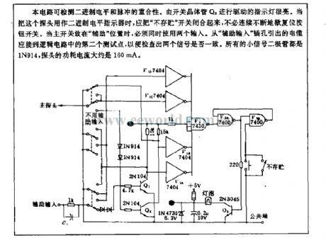
This circuit can detect repeatability of bubart system level and pulse. Because indicator light drived by switch transistor Q3 is very light, whenthis probe is used as binary system level indicator,the not stored switch should be closed,it does notneed to press reset button switch continuously. When the main switch isput on aide position, peopel must use two input together. Cable extract from aide input jack should beconnected to logic circuit's second test point to inspect the two signal being consistent or not. All small signal diodes are 1N914, and the probe power current is about 160mA.
(View)
View full Circuit Diagram | Comments | Reading(1440)
Electronic stuttering appliance circuit
Published:2011/11/9 21:45:00 Author:May | Keyword: Electronic stuttering appliance
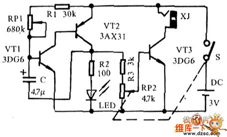
Electronic stuttering appliancecircuit is shown in the diagram, in fact, itis an electronic sound light metronome, and it utilizes rhythmed sound and light to stabilize emotion, and people will speak along with voice light rhythm to make them speak smooth gradually toreach the purpose to cure stammer.
In order to easier making, this text uses cheap components. The triodes'β value in the principle circuit only needs to higher than 20. RP1 uses small type potentiometer with reading dial, RP2 uses theradio with switch volume potentiometer. Speaker's output connects toearphone, andthe complete appliance ispackaged in small box, and LED needs a pore to show it.
(View)
View full Circuit Diagram | Comments | Reading(1594)
Light gradually, gradually eliminate type lamp dimmer circuit
Published:2011/4/24 1:18:00 Author:May | Keyword: lamp dimmer
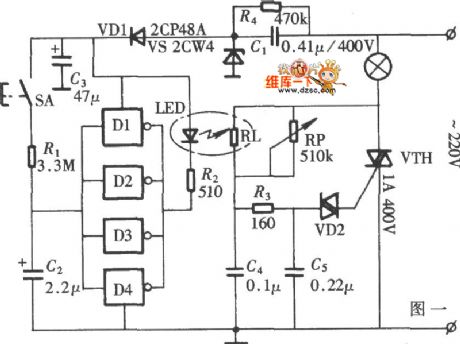
The diagram is lamp dimmer which has the function of light gradually, gradually eliminate. It does not appear the light stimulation of the human eye when the lights suddenly illuminated , and also can reduce the damage when open lamp impact current to the bulb, circuit is shown in the diagram. This circuit is LED driver circuit in optocoupler which consists of a six inverter circuit, in order to add the driver ability of the circuit, four inverters are use in parallel.
(View)
View full Circuit Diagram | Comments | Reading(2154)
Gas - smoke alarm circuit with Triac
Published:2011/8/29 1:34:00 Author:Jessie | Keyword: Gas - smoke alarm , Triac
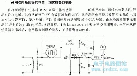
When it appears combustible gas, the conductanceof gas sensor TGS308will increase.The voltageon potentiometer RP1 sliding points increases from normal 3V to 20V. This increased voltage is added to the transistor VT1 and makes it turn on by the diode and 4.7Ω resistor, then the Triac 2N6070A is turned on. Full-wave AC voltage drives H to produce 90dB sound and alarm. H is 24V AC Delta16003168 alarm. When the gas disappears from the sensor, the circuit recovers to its original state, so the alarm automatically stops. (View)
View full Circuit Diagram | Comments | Reading(1779)
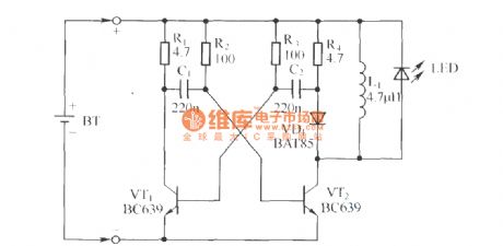
Night automatic lighting circuit with bidirectional thyristor
Published:2011/8/29 1:25:00 Author:Jessie | Keyword: bidirectional thyristor, lighting circuit
When the sunshine is very strong,light activated triode L14C1 will be connected. Diode VD3 is connected, which makes voltage of capacitor C2 decline to zero. Two-way trigger tube VD5 and two-way thyristor VT are not connected, the light is not on.
(View)
View full Circuit Diagram | Comments | Reading(1527)
Safe and reliable delay switch circuit
Published:2011/8/29 2:04:00 Author:Jessie | Keyword: delay switch circuit
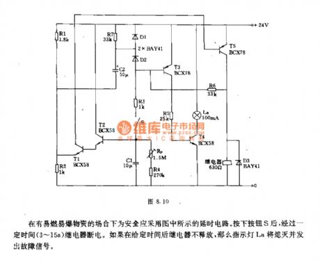
It should use the safe and reliable delay switch circuit shown as the chart in the places with flammable and explosive materials. After pressing button S anda certain time, therelay is cut off. If in a given time, therelay doesn't release, so indicator La isextinguished and sent out the fault signal.
Technical parameters: Working voltage: 24V; delay time(adjusted by R4): 3~15s. (View)
View full Circuit Diagram | Comments | Reading(1469)
Delay switch circuit with thyristor
Published:2011/8/29 2:01:00 Author:Jessie | Keyword: delay switch circuit
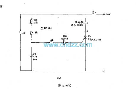
Delay switch circuit with thyristorcan control the connect and disconnect of high-power appliances. The delaying accuracy of the Figure (a) depends on regulator. Figure (b) uses two-way diode A9903 or TV503 to replace the tetrode BRY20 in Figure (a). Technical parameters: 60V ± 10%; maximum load resistor RL: 860Ω, the minimum load resistor RL: 100Ω, delay time: 0.3 ~ 3.6S.
(View)
View full Circuit Diagram | Comments | Reading(2041)
Common transistor electronic relay for controlling base
Published:2011/8/29 1:54:00 Author:Jessie | Keyword: controlling base , transistor electronic relay
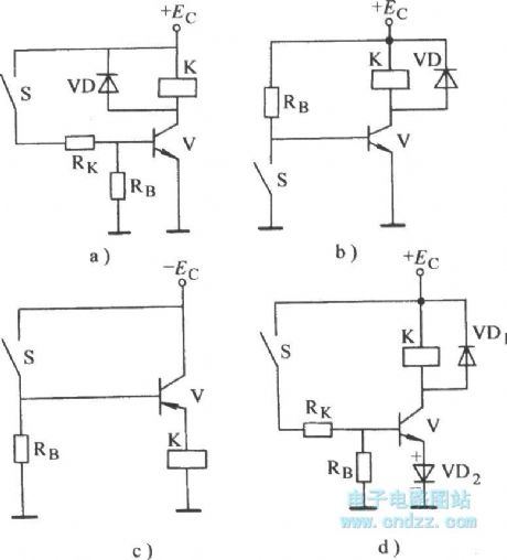
Figure A is the NPN transistor using + Ec electronic power control relay. Figure b is grounded NPN transistor control circuit. Figure c is the PNP transistor with Ec-controlled electronic relay. Figure d is the self-bias electronic relay. (View)
View full Circuit Diagram | Comments | Reading(3598)
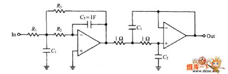
Four-stage Bessel low pass filter circuit diagram
Published:2011/7/28 0:45:00 Author:Nicole | Keyword: four-stage Bessel, low pass filter
View full Circuit Diagram | Comments | Reading(4837)
High precision selective amplifier circuit diagram
Published:2011/7/28 1:24:00 Author:Nicole | Keyword: High precision, selective amplifier
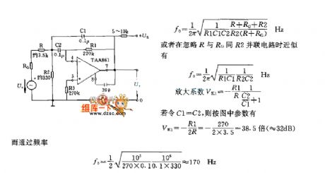
The ordinary selective amplifier adopts double T network, it requires thatthe component parameters have high precision. But if you use the circuit as shown in the figure, you can avoid it. At the low pass, the passing frequency f0 is determined by C1, and by C2 at the high pass.
(View)
View full Circuit Diagram | Comments | Reading(1643)
MOSFET resonant DC-DC converter circuit diagram with high efficiency
Published:2011/7/27 22:44:00 Author:Nicole | Keyword: DC-DC converter, MOSFET

The figure is a MOSFET resonant DC-DC converter circuit. Luo Aiye circuit works through transformer magnetic saturation and make triode fliped. In this circuit, transformer works in nonsaturated mode, it changes with arc through the grid feedback voltage of MOSFET, and to make MOSFET fliped by reducing the grid voltage.
When it isconnected to input power supply,VT1 and VT2 are added grid bias by resistors R1 and R2, due to the inhomogeneity of grid voltage UTH (threshold voltage) when MOSFET is conduction, so the lower of UTH turns on firstly.
Assuming VTI turns on firstly, there are resonance current flowing between the capacitor C1 and primary coil 2 × Np, it is produced by LC, and C1 is connected to the both ends of transformer primary coil. This current adds resonance voltage to the drain-source of other MOSFET pipe VT2.
Since the resonant voltage drops in the grid feedback loop Nf, so it reaches 0V soon. When it is lower than the grid threshold of MOSFET VTl, VTl is off. However, the resonant voltage across OV and reverse negative, the grid of VT2 is positive biased and to be conducted. Of course, the grid voltage of VTl is negative, VTl keeps cut-off state at this time.
(View)
View full Circuit Diagram | Comments | Reading(6100)
Non-isolated switching power supply circuit diagram
Published:2011/7/27 22:44:00 Author:Nicole | Keyword: switching power supply
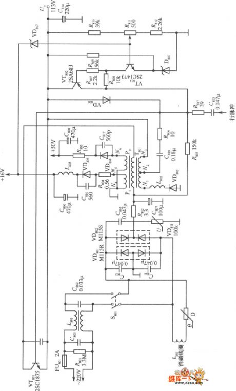
This is a useful non-isolated switching power supply circuit, it is used as the switching power supply of Peony TC - 483D color, including grid filter composed of C80l, C802, bridge rectifier circuit made of VD80l, VD802, a filter composed of R802, C807, peak voltage limiter composed of the varistor VD811; pulse oscillator consists of switch VT80l, pulse transformer T801; pulse width modulator made of VT802; error amplifier made of VT803.
It's not difficult to see from the figure, passing through the rectifier filter, 220V AC voltage is connected to output side directly by the primary winding of pulse transformer T801 and switch VT801, there is no isolation. The power supply has 16V, 50V and 113V three kinds of DC voltage output. When VT80l turns on, 113V DC output voltage will supply power to the load, while store electrical energy in C814 and magnetic energy in T801. When VT80l cut off, the N1 ~ N3 windings will produce the induced voltage with left negative and right, to make VD805 positive-skewed on, the energy stored in transformer will supply power to the load and charge to C814; C814 and L80l composition filter circuit, to make the 113V output voltage continuous and smooth.
(View)
View full Circuit Diagram | Comments | Reading(2361)
Touch delay light circuit with digital circuit(5)
Published:2011/7/28 2:07:00 Author:Nicole | Keyword: Touch delay light, digital circuit
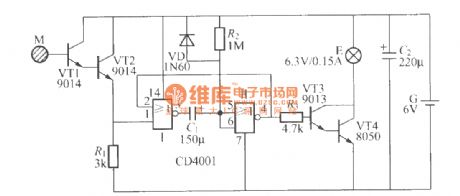
The figure is as shown, it is a touch delay light circuit which adopts dry battery as power supply, it can be put beside thepillow, at night, if you touch the sheet metal M of that small box, the small light E will keep lighting for about 2 minites automatically. (View)
View full Circuit Diagram | Comments | Reading(1173)
Light-control electric toy circuit
Published:2011/7/28 1:31:00 Author:Nicole | Keyword: electric toy
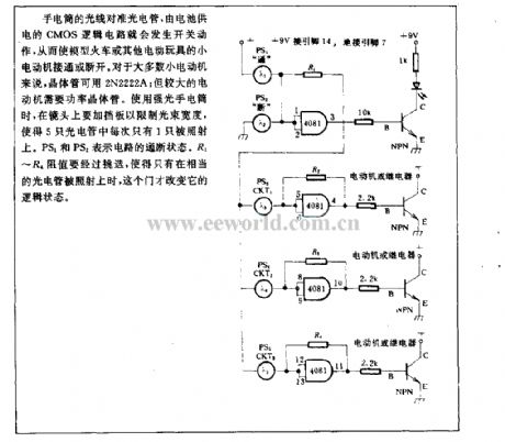
The light of flashlight aims at phototube, then CMOS logic circuit which adopts battery as power supply will occur switch action to turn on/off the motor of model train or other electric toys. To most small motor, the transistor can use 2N2222A; but the larger motors need power transistor. When using highlightflashlight, to add a baffle to lens to limit the width of light beam, then only one of phototubes will be shone. PS1 and PS2 represent the on/off state of circuit. R1~R4 resistance should be selected, only the matching phototube is shone, this gate will change its logic state. (View)
View full Circuit Diagram | Comments | Reading(1938)
Photoelectric isolating quick switch circuit
Published:2011/7/28 1:27:00 Author:Nicole | Keyword: Photoelectric, isolating quick switch
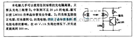
Nearly any standard photoelectric isolator can be used in this circuit, it just needs about 20μA current from photodiode D2, then the LM195 power transistor can be turned on. The negative of D2 connects to positive power supply directly, it is not connected to Q1's collector, then the influence of transistor base-collector on capacitance will be eliminated. In the case of 40V, 1A load, the speed of switch can be improved to 500ns. (View)
View full Circuit Diagram | Comments | Reading(930)
Light pen interface circuit
Published:2011/8/10 3:57:00 Author:Nicole | Keyword: light pen, interface circuit
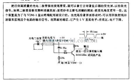
Whatever high quality photoelectric diode is fixed into exhaust pen pipe, it can face to the display screen to pick up light singal. If the diode is put in plastic lens, then it should use carbasus to sand the side of lens andto narrow the received light angle. This device is designed for matching VDM-1 display terminal. When light pen moves along the face of the screen, it can use a cathode ray oscillograph to monitor the output singal. In the dark space of screen, it will produce 5V DC level; in bright area, the level drops. (View)
View full Circuit Diagram | Comments | Reading(1164)
Ni-Cd battery discharger circuit
Published:2011/8/10 3:57:00 Author:Nicole | Keyword: Ni-Cd battery, discharger
The greatest shortcoming of Ni-Cd battery is: it has memory effect, an effective method to eliminate memory effect is: to fully discharge the Ni-Cd battery before its third or fourth charge, that is charging to Ni-Cd battery after its single section voltage drops to 0.75V, this way can make Ni-Cd battery recover capacity in time then to ensure it for normal use, but the final voltage of every single section Ni-Cd battery shouldnot belower than 0.65V, or else Ni-Cd battery will be polarity reversed and damaged due to over discharge.
(View)
View full Circuit Diagram | Comments | Reading(1747)
Data coupling electric energy with isolation performance
Published:2011/8/10 3:58:00 Author:Nicole | Keyword: data, electric energy, isolation performance
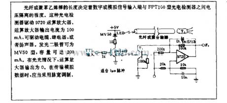
The length of optical fiber or polyrod decides the voltage isolated extent between digital or analog signal input terminal and FPT100 photoelectric detector. This photoelectric detector drives 9720 operation amplifier. The output current of operation amplifier is 100mA, it can drive cable, relay or loudspeaker. LED is MV50, its capacity can reach 200mA. If there is no light, the output of operation amplifier is 0. When it is transporting analog data, it shouldadpot PWM. (View)
View full Circuit Diagram | Comments | Reading(752)
| Pages:374/2234 At 20361362363364365366367368369370371372373374375376377378379380Under 20 |
Circuit Categories
power supply circuit
Amplifier Circuit
Basic Circuit
LED and Light Circuit
Sensor Circuit
Signal Processing
Electrical Equipment Circuit
Control Circuit
Remote Control Circuit
A/D-D/A Converter Circuit
Audio Circuit
Measuring and Test Circuit
Communication Circuit
Computer-Related Circuit
555 Circuit
Automotive Circuit
Repairing Circuit