
LED and Light Circuit
Index 22
Four-way flashing light string circuit ( 3 )(LC182)
Published:2012/9/9 22:58:00 Author:Ecco | Keyword: Four-way , flashing light string
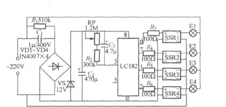
As shown in the figure, it is high-power four-way flashing light string controller using LC182. The LC182 Manifold contains rectifier amplifier, voltage-controlled oscillator and timing pulse divider, when the circuit is energized, the pin ⑥ ⑦ ① and ② appear high level in a cycle, and the circulation rate depends on the voltage-controlled oscillator's oscillation frequency. Changing pin ③ external rescap or changing audio signal from the internal rectifier amplifier input end of pin ⑤, its voltage-controlled oscillation frequency can be adjusted. SSR1 ~ SSR4 can use SP110 solid state relay, and the maximum output current is up to 3A.
(View)
View full Circuit Diagram | Comments | Reading(1152)
Water Flowing in Pipe Indicator -- July 6, 2009
Published:2012/9/9 20:30:00 Author:Ecco | Keyword: Water Flowing, in Pipe, Indicator
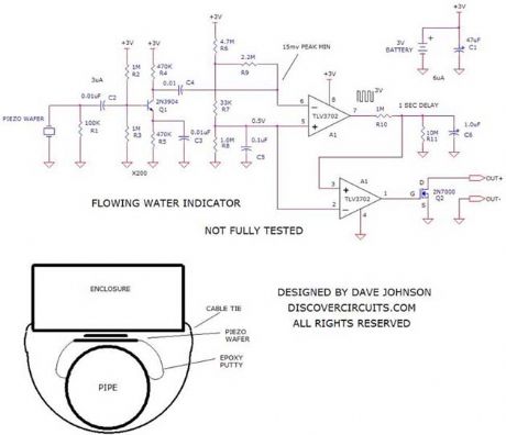
The vibrations associated with water flowing through a pipe are picked up by an inexpensive piezoelectric wafer. The signal from the wafer is first boosted by a micropower transistor amplifier and then fed to an ultra low power voltage comparator. When the vibration signal has sufficient amplitude, a FET transistor switch is activated. Drawing only 6uA, the whole circuit is powered by a lithium coin battery, which should power the circuit for many years.
Source: discovercircuits (View)
View full Circuit Diagram | Comments | Reading(917)
Capacitor buck driving LED circuit 1
Published:2012/9/6 22:40:00 Author:Ecco | Keyword: Capacitor buck , driving , LED
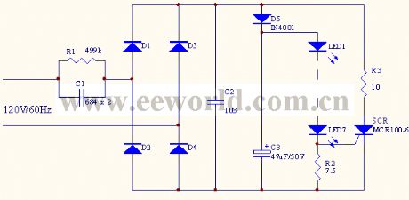
In the circuit,SCR and R3 form the protection circuit, when the current flowing through LED current is greater than the set value, SCRturns a certain angle to distribute the circuit current, so that LED works in a constant current state to avoid LEDfrom beingdamaged due to the high-voltage transient.
(View)
View full Circuit Diagram | Comments | Reading(1350)
Three-way flashing light string circuit (4)
Published:2012/9/6 21:22:00 Author:Ecco | Keyword: Three-way, flashing light string

As shown in the figure, it is a three-way flashing light string controller with novel jumping, it can make light string be lit one by one and extinguished together, then lit one by again, and it works in the cycle. The circulation rate of circuit is mainly determined by the charging time constant of R6, C2, which can be adjusted according to needs; VT1 ~~ VT3 can choose ordinary MCR100-8 small plastic unidirectional transistors; the power of each street light string is preferably at 100W or less.
(View)
View full Circuit Diagram | Comments | Reading(1090)
Incandescent Lamp Inrush Current Limiter
Published:2012/9/6 20:47:00 Author:Ecco | Keyword: Incandescent Lamp , Inrush Current Limiter
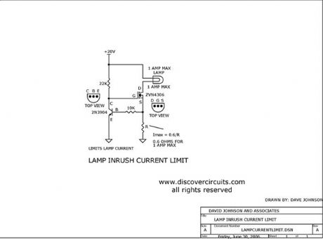
This circuit limits the large inrush current often associated with large incandescent lamps. With the components shown the current is limited to 1 amp, but it could be scaled to any desired current.
Source: discovercircuits (View)
View full Circuit Diagram | Comments | Reading(0)
40KHz Light Detector with High Ambient Light Immunity
Published:2012/9/6 20:45:00 Author:Ecco | Keyword: 40KHz, Light Detector , High Ambient, Light Immunity
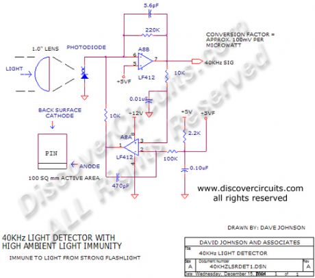
This circuit is designed for detecting infrared light modulated at around 40KHz. It?s feedback scheme cancels much of the DC component from ambient light. It?s conversion factor is about 100 millivolts per microwatt of 900nm light.
Source: discovercircuits (View)
View full Circuit Diagram | Comments | Reading(1882)
10MHz TO 20MHz LIGHT RECEIVER
Published:2012/9/6 20:44:00 Author:Ecco | Keyword: 10MHz TO 20MHz, LIGHT RECEIVER

Light power to volts conversion= approx. 15mV per microwatt at 850nM
Source: discovercircuits (View)
View full Circuit Diagram | Comments | Reading(957)
Wig/wag LED Flasher
Published:2012/9/6 20:42:00 Author:Ecco | Keyword: Wig, wag, LED Flasher
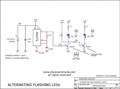
This simple circuit will flash two LEDs in an alternating fashion.
Source: discovercircuits (View)
View full Circuit Diagram | Comments | Reading(2203)
White LED is Powered by One NiMH Cell
Published:2012/9/6 20:42:00 Author:Ecco | Keyword: White LED , Powered , One NiMH Cell
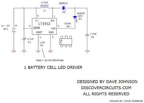
There are a lot of white LED driver circuits floating around. A popular circuit called the ?Joule Thief? can drive one white LED from a single 1.2v or 1.5v battery cell. Most of these circuits use one or two transistors to form a voltage boost circuit. Yes, they those circuit do drive a LED but they are not very efficient and they don?t do a good job of controlling the current to the LED. The circuit below uses a tiny LT1932 IC made by Linear Technology. This IC can be configured for a wide variety of LED driver needs. I have shown one simple application. The circuit takes power from one 1.2v NiMH rechargeable battery or a 1.5v disposable battery and drives a single white LED with 15ma of current. With an efficiency of about 70%, the circuit should run for about 40 hours, if a quality 2500ma-hour battery is used.
Source: discovercircuits (View)
View full Circuit Diagram | Comments | Reading(3568)
Universal 3v LED Flasher #1
Published:2012/9/6 20:41:00 Author:Ecco | Keyword: Universal , 3v , LED Flasher
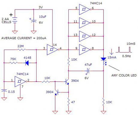
The circuit below will flash any LED color with fixed current pulses powered by a 3v battery. It uses a charge pump approach, which routes a constant current pulse through the LED, regardless of the LED voltage requirement. Using this approach, white and blue LEDs, which normally require about 3.6v can be flashed with a 3v battery. With the component values selected, the LED is hit with 15ma current pulses lasting about 10ms every two seconds. This keeps the average current draw from a 3v battery to about 200uA. The circuit relies on a cheap 74HC14 hex Schmitt trigger inverter IC. One inverter forms a pulse generating oscillator. Other inverters are ganged together to increase the drive current. A two transistor circuit forms a constant sinking current controller.
Source: discovercircuits (View)
View full Circuit Diagram | Comments | Reading(1381)
Table Lamp with auxiliary 12v Automotive Style LED Light
Published:2012/9/6 20:41:00 Author:Ecco | Keyword: Table Lamp , auxiliary, 12v , Automotive Style, LED Light
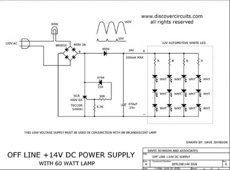
This circuit provides about one watt of non-isolated DC power for an automotive type 12v LED array lamp in addition to a standard incandescent table lamp.
Source: discovercircuits (View)
View full Circuit Diagram | Comments | Reading(7704)
Super Bright 3v Powered LED Flasher (April 22, 2009)
Published:2012/9/6 20:40:00 Author:Ecco | Keyword: Super Bright , 3v Powered, LED Flasher
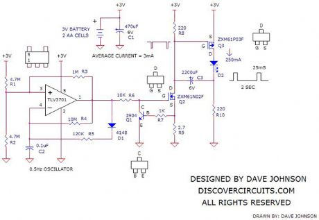
I have posted several kinds of LED flashers over the years. This is yet one more flasher, designed to flash any high power LED of any color. It hits the LED with a 25ms 250ma pulse once every 2 seconds. This works out to an average current about 3ma. It is powered by any 3v source. I suggest two AA cells but a single 3v lithium coin type cell will also work. With fresh AA cells, the light should flash for about two weeks. The light flash is very intense and is perfect for any attention getting night time application.
Source: discovercircuits (View)
View full Circuit Diagram | Comments | Reading(1722)
SIMPLE WHITE LED NIGHT LIGHT
Published:2012/9/6 20:40:00 Author:Ecco | Keyword: SIMPLE, WHITE LED , NIGHT LIGHT
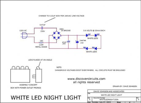
This simple circuit is designed to plug into a standard AC electrical outlet. It uses four super bright white light emitting diodes (LED) in conjunction with a capacitor coupled full wave rectifier circuit. The LEDs are mounted in a box and are angled slightly to bounce the light off of a nearby wall. The light should last about 10 years. The circuit draws less than one half of one watt of power and can therefore run continuously. In spite of the low power, the LEDs provide sufficient illumination for most night light applications. Circuit component values for both 120vac and 240vac are shown.
Source: discovercircuits (View)
View full Circuit Diagram | Comments | Reading(2162)
Remote LED Indicator Light -- December 27, 2008
Published:2012/9/6 20:39:00 Author:Ecco | Keyword: Remote, LED Indicator , Light
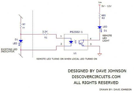
There are times when you would like to transmit a signal from one LED indicator light to second LED at another location. The circuit below works well for this application. It takes advantage of the fact that the internal infrared LED inside an opto-isolator has a lower voltage drop than the visible LED being tapped into. Using a Darlington type opto-isolator also means very little current needs to be diverted to the isolator. The photo-darlington side of the isolator can be used to turn on the remote LED using any convenient DC source. In automotive applications, this is often 12v. You can also use the output of the opto-isolator to drive a low power beeper. This might be handy for something like a ?check engine? or a ?windshield washer fluid light.
Source: discovercircuits (View)
View full Circuit Diagram | Comments | Reading(1486)
Lighthouse LED Flasher
Published:2012/9/6 20:38:00 Author:Ecco | Keyword: Lighthouse, LED Flasher
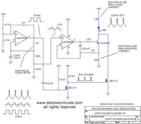
This was originally designed for a model in a HO train set. It simulates the behavior of the light from a lighthouse. The LED intensity gradually increases, then flashes with a bright light and finally decreases slowly in intensity.
Source: discovercircuits (View)
View full Circuit Diagram | Comments | Reading(1199)
High Power LED Flasher August 3, 2008
Published:2012/9/6 20:37:00 Author:Ecco | Keyword: High Power, LED Flasher
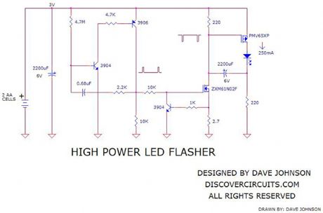
Power LEDs are becoming more popular these days. The DC input power to these devices ranges from 1 watt to 5 watts. Normal LEDs only receive about 0.05 watts. At this higher power, these devices can emit a lot of light. You can buy them in just about any color in the rainbow but white seems to be the most popular. One application for these devices is a flashing light. If the flash duration and flash rate is kept low, the average current can be low enough that even a small battery can last quite a while.
Source: discovercircuits (View)
View full Circuit Diagram | Comments | Reading(1418)
AC Line Powered LED Pilot Light
Published:2012/9/6 20:36:00 Author:Ecco | Keyword: AC Line, Powered , LED Pilot, Light
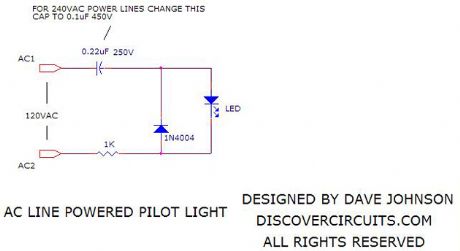
This simple circuit can be used to light a LED indicator lamp, powered from the 120vac line. I have included component values for 240vac lines as well.
Source: discovercircuits (View)
View full Circuit Diagram | Comments | Reading(4956)
12v Lamp Current Indicator
Published:2012/9/6 20:35:00 Author:Ecco | Keyword: 12v, Lamp, Current Indicator
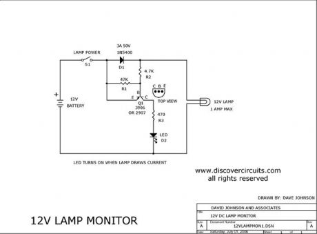
This circuit turns on a LED indictor light whenever DC current flows into a 12v lamp.
Source: discovercircuits (View)
View full Circuit Diagram | Comments | Reading(3433)
40KHz TV-VCR LIGHT SOURCE REPEATER
Published:2012/9/6 20:26:00 Author:Ecco | Keyword: 40KHz , TV-VCR, LIGHT SOURCE REPEATER
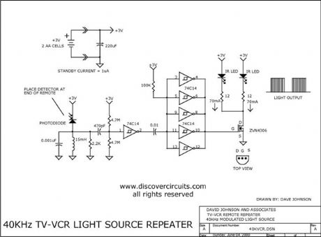
This circuit is designed to be placed directly in front of a standard TV or VCR remote. The exiting light pulses produced by the circuit match the pulses from the remote but are about 10 times more powerful. Using the device, the remote can operate a TV or VCR over three times the normal distance.
Source: discovercircuits (View)
View full Circuit Diagram | Comments | Reading(2)
Ramping LED Driver
Published:2012/9/6 20:10:00 Author:Ecco | Keyword: Ramping, LED Driver
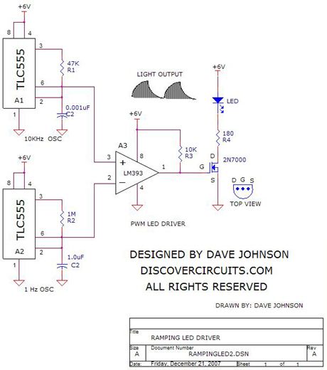
The circuit below was designed to drive a LED with an intensity ramping mode. Two 555 timers generate two different triangle waveforms. The upper device generates a 10KHz signal while the lower unit produces a 1Hz signal. The two signals are fed to a voltage comparator. The result is a pulse width modulation (PWM) signal, which with the aid of the FET, drives the LED in such a way that its average light output slowly ramps from about zero light to maximum and then slowly dims back down. The circuit should operate over a supply voltage ranging from 3v to 12v. You can easily vary the ramping time by changing the value of the 1M resistor. For an interesting effect, you can place a 1N4148 diode in parallel with the 1M resistor, with the cathode (banded end) side connected to pin 3.
Source: discovercircuits (View)
View full Circuit Diagram | Comments | Reading(1448)
| Pages:22/72 At 202122232425262728293031323334353637383940Under 20 |
Circuit Categories
power supply circuit
Amplifier Circuit
Basic Circuit
LED and Light Circuit
Sensor Circuit
Signal Processing
Electrical Equipment Circuit
Control Circuit
Remote Control Circuit
A/D-D/A Converter Circuit
Audio Circuit
Measuring and Test Circuit
Communication Circuit
Computer-Related Circuit
555 Circuit
Automotive Circuit
Repairing Circuit