
LED and Light Circuit
Index 32
MAX16823 White LED driver circuit diagram
Published:2011/8/16 20:41:00 Author: | Keyword: White LED driver
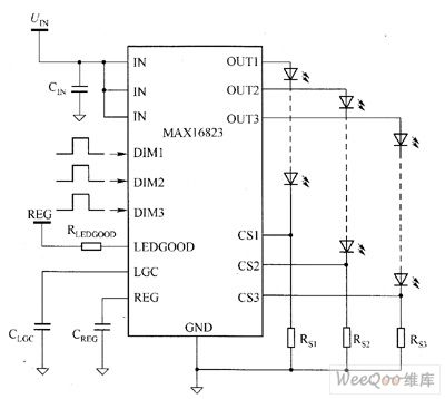
MAX16823's main technical characteristics are as follow. ① 5.5 ~ 40V operating voltage range. ② adjustable constant output current (5 ~ 70mA, it uses external BJT to reach 2A). ③ ± 5% output current accuracy. ④ white LED open detection. ⑤ 3 separate high-pressure DIM inputs. ⑥ Built-in 3-channel, low dropout (maximum value is 0.7V) and adjusting components. ⑦ undervoltage lockout function(output short-circuit protection and thermal shutdown). ⑧it contains 3.4V regulator to provide 4mA current. ⑨ low 203mV precision current-sense reference.
(View)
View full Circuit Diagram | Comments | Reading(1453)
MAX16818 White LED driver circuit diagram
Published:2011/8/16 20:45:00 Author: | Keyword: White LED driver
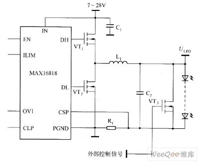
MAX16818's main technical characteristics are as follow. ① high-current white LED driver controller IC, the output current is up to 30A. ② it uses average current mode control, true differential remote sensing input technology. ③ programmable switching frequency is synchronized by an external controller in the 125kHz ~ 1.5MHz range. ④ 4.75 ~ 5.5V or 7 ~ 28V input voltage range. ⑤ it contains a 4A gate driver. ⑥ clock output is used for 180 ° out of phase work. ⑦ it has output overvoltage protection and hiccup mode over-current protection and thermal shutdown protection.
(View)
View full Circuit Diagram | Comments | Reading(1397)
High power led driver boost regulator circuit diagram
Published:2011/8/17 2:57:00 Author:Rebekka | Keyword: High power , led driver , boost regulator
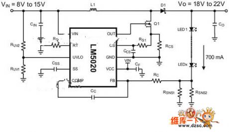
When the input voltage of LED system applications is less than the minimum entire series string of forward voltage drop, you need a boost regulator. In the low-power applications, the switched capacitor boost converter is widely used. However, when the current is about 100mA or more, the efficiency will drop rapidly. Inductive boost regulators also need some output voltage to provide a higher part of the input voltage.
Picture: High power led drive boost regulator circuit.It chooses an circuit that is used for driving an LED array typical step-up regulator. The reduction voltage circuit is shown in figure 3a and 3b. Previously it is allowed the dynamic movement in the output current while the output voltage regulation system. It has been converted to allow the dynamic movement in the output voltage andoutput current while maintaining the system at present.
(View)
View full Circuit Diagram | Comments | Reading(3254)
Transistor 2SC5003, 2SC5250 internal circuit diagram
Published:2011/8/17 3:20:00 Author:Rebekka | Keyword: Transistor , internal circuit

Here is the schematic diagram of the transistor 2SC5003, 2SC5250 internal circuit diagram:
(View)
View full Circuit Diagram | Comments | Reading(1597)
The serial LED circuit driven by inductance booster transformer IC
Published:2011/8/11 21:38:00 Author:Borg | Keyword: serial LED, inductance booster transformer, IC

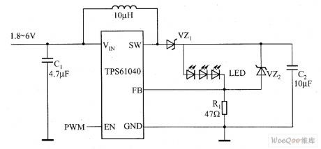
The serial white light LED circuit driven by inductance booster transformer is shown in the figure, by changing the values of R1 and VZ2 in the figure, the booster topology can drive more than one serial white light LEDs (HSMW-C850). By using the 47Ω ground resistor and 1.233V Vref, the component can provide with a 26mA current.
(View)
View full Circuit Diagram | Comments | Reading(1203)
The simplest capacitor step-down dirve LED circuit
Published:2011/8/11 21:26:00 Author:Borg | Keyword: capacitor, step-down dirve, LED
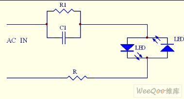
This is a simplest capacitor step-down applicational circuit, in the circuit, the AC voltage is rectified by 2 backward parallel LEDs after it is stepped down. The circuit can be used in lighting lamps, key indicators and other situations with low standards.
(View)
View full Circuit Diagram | Comments | Reading(1948)
The amplifier exposer circuit
Published:2011/8/15 21:47:00 Author: | Keyword: amplifier, exposer
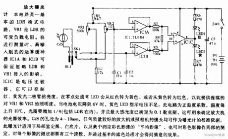
The amplifier exposer circuit The circuit is a basic LDR bridge circuit, VR1 is the loading resistor of LDR. When testing, the high input impedance computing buffers IC1A and IC1B can make sure that the connection of LDR and VR1 has no effect. IC1C is the voltage comparator, which can control the brightness of the red and yellow LED. When it is at the zero point, the LED will change into red from yellow, or change from yellow into red, so it can provide with continuous illumination for VR1 and VR2. When the voltage of the cell drops to 6V, the yellow LED will indicate that the power is low.
(View)
View full Circuit Diagram | Comments | Reading(933)
The 4-bit and 9-stage LED display driver LED circuits
Published:2011/8/18 7:26:00 Author: | Keyword: LED, display driver
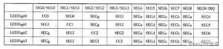
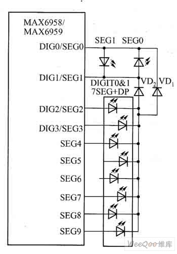
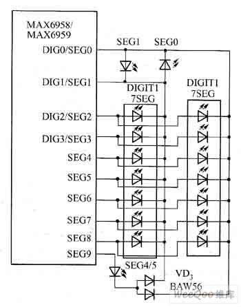
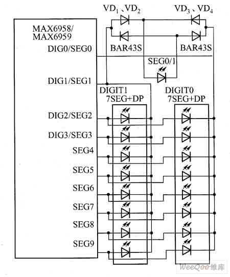
MAX6958/MAX6959 are 4-bit and 9-stage LED display driver LED circuits, they are equipped with the 6-bit PWM(64-stage) brightness technology, which can adjust the average currents of all the LEDs at the same time. By expanding MAX6958/MAX6959 functions, the single pixel stage(LED) control can be fulfilled. MAX6958/MAX6959 are equipped with a multi-line reuse technology with a few pins, it only needs 10 drive pins to drive 36 stages. The standard connection method of MAX6958/MAX6959 is shown in the table.
(View)
View full Circuit Diagram | Comments | Reading(1453)
25W electronic neon circuit diagran
Published:2011/8/11 22:25:00 Author:Ecco | Keyword: 25W electronic neon
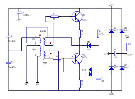
Operating frequency is110KHz; Output voltage is2500V; Input AC 220V; LED tube length is 2 m.
(View)
View full Circuit Diagram | Comments | Reading(2693)
BA2101 touching stepping dimmer circuit
Published:2011/8/8 20:47:00 Author:Ecco | Keyword: touching stepping dimmer
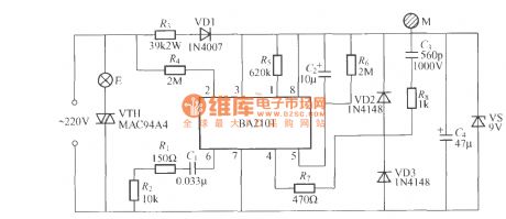
The touching stepping dimmer circuit shown as the chart uses BA2101 dimming ASIC, and it is very suitable for lamp dimming. Touching the electrode M can make the brightness of E lamp change in the cycle of weak, medium, strong, turning off, weak ... .
(View)
View full Circuit Diagram | Comments | Reading(945)
Chicken farm automatic filling light 3
Published:2011/8/11 22:20:00 Author:Ecco | Keyword: Chicken farm, automatic filling light
The chicken farm automatic filling light circuit is composed of the power supply circuit, light control circuit, timing circuit and control implementation circuit, and it is shown in Figure 4-10. Power supply circuit is composed of the power switch S, power transformer T, rectifier diodes VD1-VD4, filter capacitors Cl, C2, and three-terminal voltage regulator integrated circuit ICI. Light control circuit is composed of the photosensitive resistor RG, potentiometer RPl, resistor Rl, capacitor C3 and the time-base integrated circuit IC2. Timing circuit is composed of the timer integrated circuit IC3, resistors R2, R7, potentiometer RP2, capacitor C5 and diode VD5. Rl-R7 select the 1/4W metal film resistors or carbon film resistors.
(View)
View full Circuit Diagram | Comments | Reading(1001)
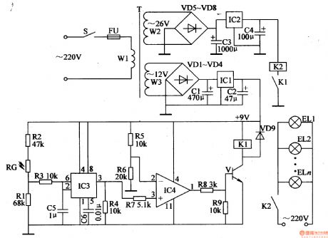
Chicken farm automatic filling light 2
Published:2011/8/11 22:24:00 Author:Ecco | Keyword: Chicken farm , automatic filling light
The chicken farm automatic filling light circuit is composed of the power supply circuit, metering circuit and dimming circuit, and it is shown in Figure 4-9. Power supply circuit is composed of the power switch S, power transformer T, rectifier diodes VDl-VD4, filter capacitors C2, C3, three-terminal voltage regulator integrated circuit IC, current-limiting resistor R4 and power indicator light-emitting diode VL. Metering circuit is composed of the photosensitive resistor RC, potentiometers RPl, RP2, resistors Rl, R2 and transistors Vl-V3. Dimming circuit consists of transistor V3, single-junction transistor VU, thyristor VT, resistors R2, R3, capacitor Cl and filling light EL.
(View)
View full Circuit Diagram | Comments | Reading(1756)
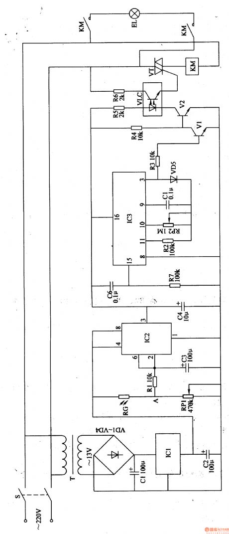
Chicken farm automatic filling light 1
Published:2011/8/10 2:29:00 Author:Ecco | Keyword: Chicken farm, automatic filling light
The chicken farm automatic filling light is composed of the power supply circuit, light control circuit, driver control circuit and lighting circuit, and it is shown as the Figure 4-8. Power supply circuit consists of the power switch S, fuse FU, power transformer T, rectifier diodes VDl-VD8, filter capacitors Cl-C4 and three-terminal voltage regulator integrated circuits ICl, lC2. Light control circuit by the photosensitive resistor RG, resistors Rl-R3, capacitor C5, C6 and time-base integrated circuit IC3. Drive control circuit consists of the resistors R4-R9, operational amplifier integrated circuit IC4, diode VDg, transistor V and relay Kl.
(View)
View full Circuit Diagram | Comments | Reading(1438)
Auto-dimming lamp
Published:2011/8/15 21:07:00 Author:Ecco | Keyword: Auto-dimming lamp
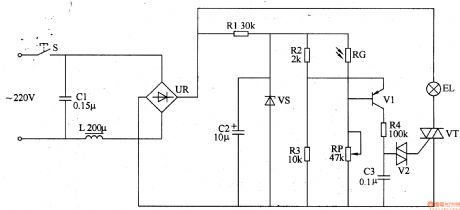
The auto-dimming lamp circuit is composed of the power supply circuit and light control circuit, and it is shown in Figure 3-201. Power supply circuit is composed of the power switch S, filter capacitors Cl, C2, inductor L, bridge rectifier UR, current limiting resistor Rl and the voltage regulator diode VS. Light control circuit is composed of the photosensitive resistor RG, resistor R4, potentiometer RP, capacitor C3, transistor V1, two-way trigger diode V2 and thyristor VT. Rl selects the 1/2W metal film resistor; R2-R4 use the 1/4W carbon film resistors or metal film resistors. RP uses the solid organic or synthetic membrane potentiometer.
(View)
View full Circuit Diagram | Comments | Reading(1818)
Southeast Ling Sheng fog lamp electric systemg circuit
Published:2011/8/6 21:36:00 Author:leo | Keyword: Fog lamp, electric system
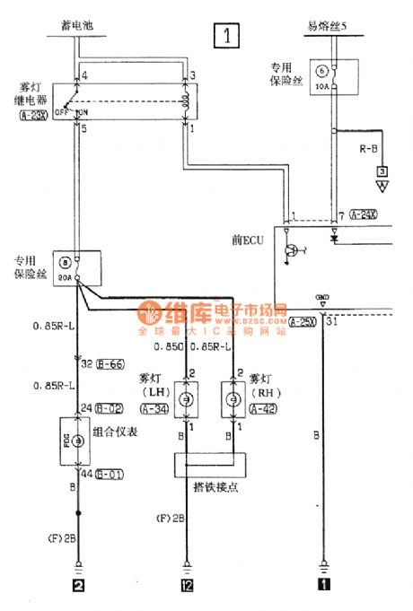

View full Circuit Diagram | Comments | Reading(1086)
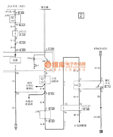
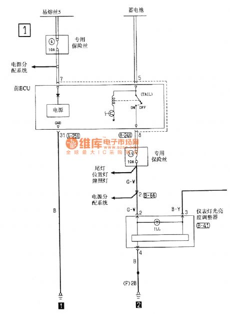
Southeast Ling Sheng instrument lamp brightness selector electric system circuit
Published:2011/8/10 19:09:00 Author:leo | Keyword: Lamp brightness selector, instrument, Southeast Ling Sheng
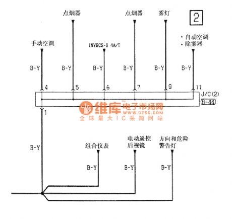
View full Circuit Diagram | Comments | Reading(921)
Flashing LED circuit for monitoring remote power resource voltage
Published:2011/8/10 19:10:00 Author:leo | Keyword: Flashing LED, monitoring voltage, power resource voltage
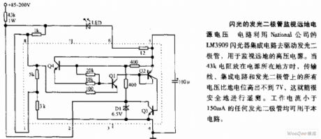
This circuit uses LM3909 flasher integrated circuit produced by National Company to drive LED for monitoring the voltage of remote power resource. When the resistance of 43kohms is placed in the area of power resources, the voltage of transferring wires, integrated circuit and LED does not pass over more than 7V than ground, the voltage of remote power resource will be tested safely. And the work current should be smaller than 150mA. (View)
View full Circuit Diagram | Comments | Reading(977)
The typical application circuit of HFC68 audio lantern control IC
Published:2011/8/8 20:15:00 Author:Ecco | Keyword: typical application circuit, audio lantern , control IC
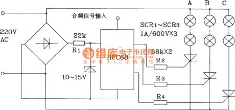
HFC68 is a special sound and light synchronization Lantern control IC, which is mainly used for sound rotating, chase, dance lights, karaoke 0K changing lights, and sound and lightcontrol Christmas tree lights.
(View)
View full Circuit Diagram | Comments | Reading(1666)
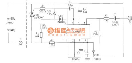
SS0619 Touching stepping dimmer circuit diagram
Published:2011/8/5 2:33:00 Author:Ecco | Keyword: Touching stepping dimmer
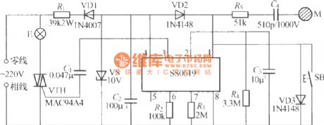
The touching stepping dimmer shown as the chart is composed of SS0619 IC, and it has touching and keying modes, which can make the brightness of E change optionally at the cycle of low, medium, bright, turning off .
(View)
View full Circuit Diagram | Comments | Reading(868)
SS0614 Touching stepless dimmer circuit
Published:2011/8/5 2:38:00 Author:Ecco | Keyword: Touching stepless dimmer
The touching stepless dimmer shown as the chart is composed of SS0614 IC, and it uses two-wire system connection, which does not need to change the original wiring in the room. Touching M can make the voltage on the two ends of the lampbe adjustablein 27 ~200V.
(View)
View full Circuit Diagram | Comments | Reading(879)
| Pages:32/72 At 202122232425262728293031323334353637383940Under 20 |
Circuit Categories
power supply circuit
Amplifier Circuit
Basic Circuit
LED and Light Circuit
Sensor Circuit
Signal Processing
Electrical Equipment Circuit
Control Circuit
Remote Control Circuit
A/D-D/A Converter Circuit
Audio Circuit
Measuring and Test Circuit
Communication Circuit
Computer-Related Circuit
555 Circuit
Automotive Circuit
Repairing Circuit