
LED and Light Circuit
Index 38
TWO_CASCADED_BAR_GRAPH_DISPLAY_DRIVERS
Published:2009/7/13 4:27:00 Author:May
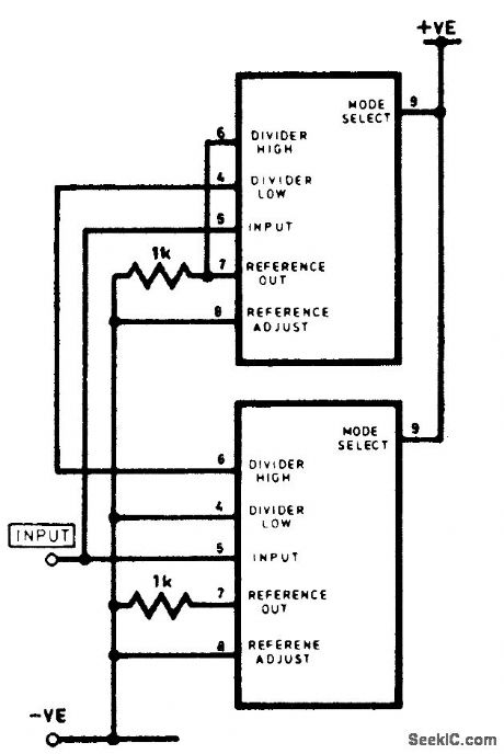
This shows how to cascade two bar-graph dis-play drivers. (View)
View full Circuit Diagram | Comments | Reading(998)
BRIDGE_RECTIFIER_LED_LIGHT_STRING
Published:2009/7/13 4:26:00 Author:May
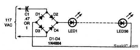
This circuit has a full-wave bridge rectifier feeding the LED string. With a 0.47-μF capacitor, as shown, the string's current was about 12 mA. If you substitute a 1-μF unit, the current will go up to about 20 mA, allowing you to add additional LEDs without suffering too severe a loss in brightness. (View)
View full Circuit Diagram | Comments | Reading(1391)
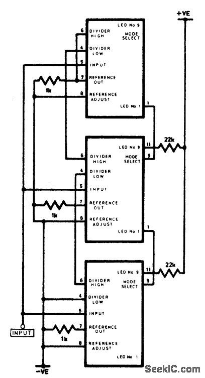
THREE_CASCADED_BAR_GRAPH_DISPLAY_DRIVERS
Published:2009/7/13 4:25:00 Author:May
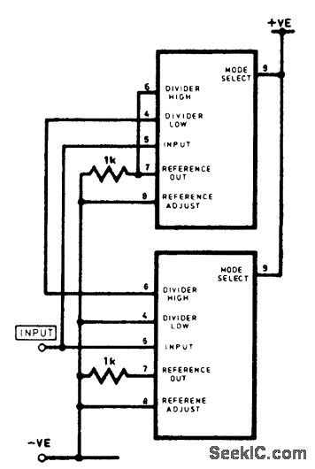
This shows how to cascade three bar-graph display drivers. The basic scheme can be extended to four or more drivers, if desired. (View)
View full Circuit Diagram | Comments | Reading(1263)
LED_AC_PILOT_LAMP_CIRCUIT
Published:2009/7/13 4:25:00 Author:May
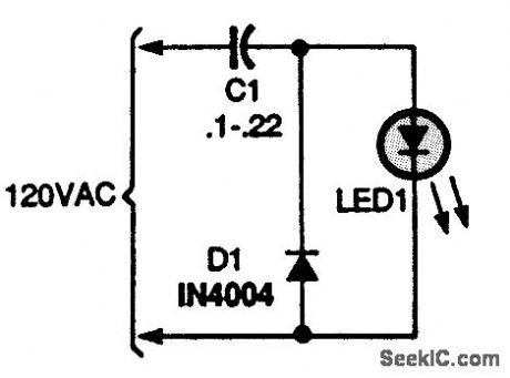
This circuit places an LED in an ac circuit, where it operates as a pilot lamp. The capacitance value sets the LED's current. For 120-Vac operation, a 0.1-μF, 400-V capacitor will result in a 5- to 10-mA current, and a 0.22-μF unit will produce approximately 20 mA of current. (View)
View full Circuit Diagram | Comments | Reading(1995)
SURROUND_SOUND_INDICATOR
Published:2009/7/13 4:24:00 Author:May
The circuit indicates, with the aid of two LEDs, whether or not the input signal contains surround data. The criterion for this is the phase difference between the two channels: If this is zero, there is no surround data. In the circuit diagram, if there is a phase difference between the two channels, the output levels of comparators IC1b and IC1c will differ. These outputs are constantly compared by XOR gate IC2c; if there is a difference, the output of the gate will go high. Depending on the output state, the red or green half of D1will be actuated via gate IC2d, which is here connected as an inverter. If there is a pure surround signal, the red half will light brightly; if there is a mono signal, the green half will light. If the input is a standard stereo signal, the rapid changes in the output of IC2c will cause the diode to appear yellow-orange. (View)
View full Circuit Diagram | Comments | Reading(1045)
ECONOMICAL_LED_BAR_DISPLAY
Published:2009/7/13 4:22:00 Author:May
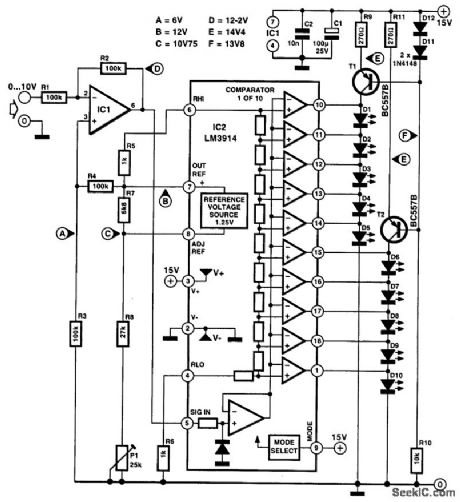
A particular difficulty with LED bar displays is the high current drain. In the diagram, LED driver LM3914 controls a chain of LEDs instead of, as is usual, a number of parallel-connected LEDs. This means that in principle only a single diode current is needed to make several LEDs light. The cost of this, of course, is a higher supply voltage because account must be taken of a number of diode forward voltages. The economizing effect is strengthened if high-efficiency LEDs are used. In the diagram, the current drain of about 15 mA is less than half that of the standard application (32 mA). (View)
View full Circuit Diagram | Comments | Reading(5010)
LIQUID_LEVEL_CONTROL
Published:2009/7/13 4:16:00 Author:May
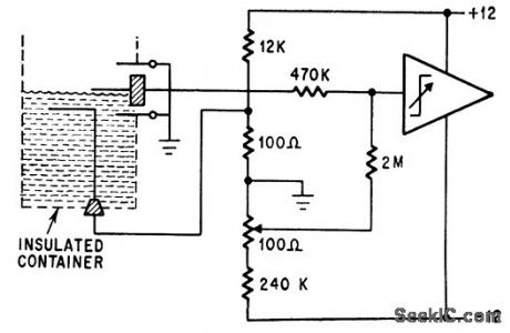
Operational trigger has sufficient sensitivity even for distilled water and alcohol, to control level within 1 mm.-P. Lefferts, Operational Trigger For Precise Control, Electronics, 37:28, p50-55. (View)
View full Circuit Diagram | Comments | Reading(1572)
MULTICOLOR_LED_DRIVER
Published:2009/7/13 4:15:00 Author:May
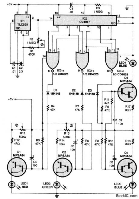
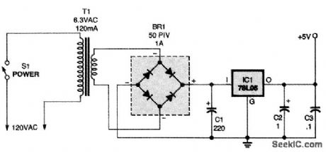
A TLC555 CMOS timer, IC1, is configured as a square-wave generator that has an adjustable time period of about 2 to 7 s. That output drives IC2, a CD4017 CMOS Johnson counter, which provides the six decoded output steps necessary to trigger the three additive and three subtractive primary color combinations. A CD4025 CMOS triple three-input NOR gate, IC3, gates the six outputs to the proper LED current sources, thereby maintaining the correct color-mixing sequence. Four MPSA64 PNP Darlington transistors (Q1 to Q4) are configured as gated current sources, with capacitors C4 to C7 providing long time constants that allow LED1 to LED4 to ramp up and down in intensity. This allows the color changes to be continuous, rather than in six abrupt steps. Power for the circuit is provided by a 5-V supply. Transformer T1 steps down the voltage from a wall outlet to 6.3 Vac, recti-fied by BR1 and regulated by IC1, a 78L05. (View)
View full Circuit Diagram | Comments | Reading(1891)
SOUND_CONTROLLED_LAMP
Published:2009/7/13 4:12:00 Author:May
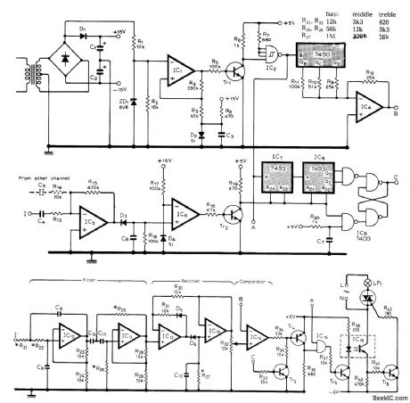
Zero-voltage switching achieves interference-free proportional control of lamp intensity by sound source. Both inputs to AND gate IC15 must be high for triac to tum on. 0ne input is from zero-crossing detector IC1, Tr1,. and IC2, which produces 100-Hz series of positive-going pulses.Other input is provided by filterirectifier/com-parator circuit, Inverting input of comparator IC14, is fed by DAC IC14 which produces stepped ramp waveform from outputs of 7490 counter IC3. Counter is connected to count to 5 before resetting internally, giving five possible brightness levels for lamp. Opamps IC5, and IC6, detect when audio input falls below about 10 mV and then release IC7-IC9, from reset stage so the two 4-bit counters start counting 100-Hz waveform.Resetting occurs again when audio input next passes 10-mV level. Lamp automatcaUy turns on when music stops. All ICs are 741 or equivalent except as marked. Unmarked diodes are 1N4148, C1, and C2 are 100-nF polyester electrolytics, and all transistors are general-purpose types. Resistor values in table are for threechannel system,but more channels can be used if desired.-A. R. Ward, Sound-to Light Unit, Wireless World, July 1978, p 75.
(View)
View full Circuit Diagram | Comments | Reading(1167)
AC_DC_SUPPLY_LED_CIRCUIT
Published:2009/7/13 4:12:00 Author:May
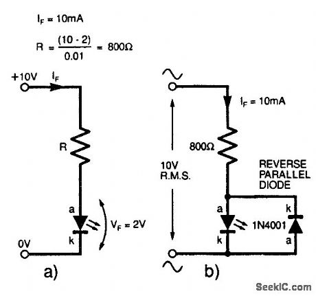
(a) Series resistor calculation; (b) using an LED on an ac supply. (View)
View full Circuit Diagram | Comments | Reading(838)
HIGH_INTENSITY_LED_CIRCUIT
Published:2009/7/13 4:08:00 Author:May
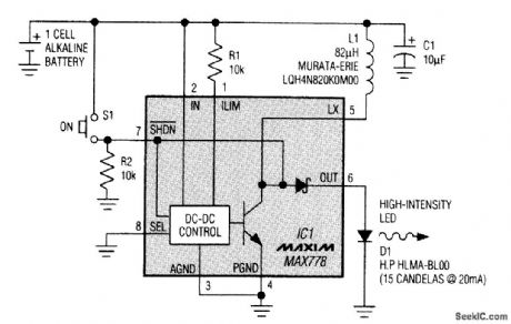
The forward voltage for high-intensity LEDs (1.5 to 2.5 V) is too large for operation with one-cell batteries. The circuit shown overcomes this limitation with a boost-regulator technique-it drives controlled current pulses through the LED, regardless of the LED's forward voltage, and operates on input voltages from 6.2 V to below 1 V. The circuit is useful for bicycle lights, beacons, alarms, flashlights, and low-power indicators. IC1 is normally part of a regulated boost converter, but, in this case, it simply transfers energy without regulating the output. Omission of the usual rectifier and output filter capacitor makes the circuit compact, as does the high switching frequency (about 175 kHz).Programming resistor R1 sets the LED intensity by setting a peak current for the inductor and LED.A 10-kΩ value for R1 sets the approximate peak at 75 mA, and the average LED current at about 26 mA. A shutdown command tums off the OUT terminal completely, even if cell voltage exceeds the LED's forward voltage, by turning off the diode internal to IC1. (During shutdown, most step-up converters exhibit a troublesome dc path from the battery through the coil and diode to the load.) This circuit draws about 8 μA during shutdown and about 60 mA during normal operation. It operates for 35 hours continuously on one AA (or R4 size) alkaline cell. (View)
View full Circuit Diagram | Comments | Reading(1199)
FOUR_LED_BCD_DISPLAY
Published:2009/7/13 4:06:00 Author:May
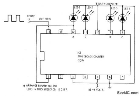
Square-wave input pulses are counted by 7490 IC that drives LEDs indicating count in binary format up to 10 and then recycling Can be used for classroom demonstrations of counters,flip-flop action, and binary counting,Pulses can be obtained from UJT clock circuit operating at audio rate.-F M Mims, Computer Circuits for Experimenters, Radio Shack, Fort Worth, TX, 1974, p 85-93 (View)
View full Circuit Diagram | Comments | Reading(3559)
OIL_PRESSURE_ACTUATED_RUNNING_LIGHTS
Published:2009/7/13 4:03:00 Author:May
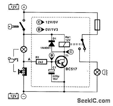
Motorcycles and cars that are not equipped with (automatic) day running lights can be so equipped with the present circuit. The circuit is connected to the oil-pressure indicator. When the engine is not running, the contacts of the oil-pressure sensor in the engine block are closed. When the ignition is then switched on, the oil-pressure light comes on. The potential at A is then low, and nothing happens. When the engine is running, oil-pressure builds up, whereupon the contacts open and the indicator light goes out. The potential at A is then high so that T1 comes on and the relay becomes energized. The relay contact in series with the headlights closes so that the headlight is switched on. When the engine is switched off, the relay is deenergized and the headlights go out. (View)
View full Circuit Diagram | Comments | Reading(2636)
SLAVE_FLASH
Published:2009/7/13 3:42:00 Author:May
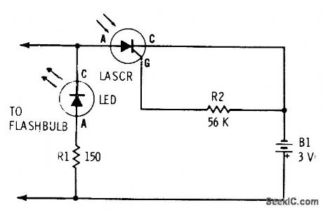
Remote fiashtube having no connection with camera is fired by light-activated SCR (LASCR) when triggered by main fiash of camera. Used to provide illumination at greater depth than main flash range, to soften sharp shadows, and to provide backlighting for fiash photographs. LED is indicator showing that circuit has been triggered, reminding photographer that new flash lamp should be inserted.-F.M. Mims, Transistor Projects, Vol.1, Radio Shack, Fort Worth, TX, 1977, 2nd Ed., p79-85. (View)
View full Circuit Diagram | Comments | Reading(2538)
MOTOR_TRANSIENT_ANTICIPATOR
Published:2009/7/13 3:36:00 Author:May
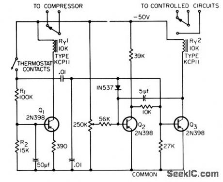
Disconnects battery supply of sensitive counters for preset interval during switching period of nearby air conditioner, to avoid extraneous counts by switching transients from compressor motor and control relays.-C. H. Harris, Motor Transient Anticipator, EEE,13:5, p45-46. (View)
View full Circuit Diagram | Comments | Reading(771)
ANTENNA_TUNING_INDICATOR
Published:2009/7/13 3:27:00 Author:May
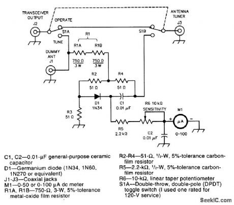
The stealth antenna tuning indicator consists of a sensitive reflected-power bridge and indicator (R2 to R6 and associated components) and a switch (S1) that lets you route your transceiver's power into a dummy antenna (TUNE) or your antenna system (OPERATE). One more component, R1 (a resistance cortsisting of two separate 3-W resistors, R1A and R1B), leaks just enough of your transmitter's power to the bridge and your antenna system to allow low-interference tune-up when S1 is set to TUNE. (View)
View full Circuit Diagram | Comments | Reading(1917)
PACKET_RADIO_TUNING_INDICATOR
Published:2009/7/13 3:16:00 Author:May
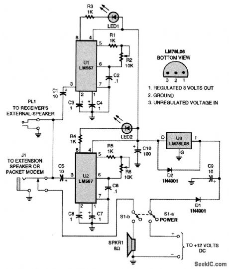
The tuning indicator is simply two identical tone decoders adjusted to different frequencies that share a power supply. When a decoder receives a signal of the right frequency, it lights its LED. Simply tune the circuit so that both LEDs illuminate. (View)
View full Circuit Diagram | Comments | Reading(1046)
TRANSISTOR_BETA_DISPLAY
Published:2009/7/16 20:45:00 Author:Jessie

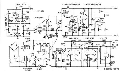
Falloff in beta with increasing collector current is displayed on auxiliary cro over range of 0 to 200 ma, for constant collector voltages up to 8 v.-R.Zuleeg and J. Lindmayer, Sweep Equipment Displays Transistor Beta, Electroics,31:49, p 100-101. (View)
View full Circuit Diagram | Comments | Reading(1089)
RASTER_DISPLAY
Published:2009/7/16 20:35:00 Author:Jessie
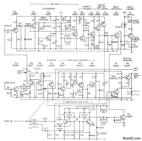
Sixteen digital words can be displayed simultaneously on ordinary scope, For troubleshooting in data processors. Sweep generators are controlled by two-bit gap between words.-B. S. While, Circuit Converts One-Trace Scopes to Raster Display, Electronics, 36:48, p 33-35. (View)
View full Circuit Diagram | Comments | Reading(1075)
TWO_SIGNAL_DISPLAY
Published:2009/7/16 20:23:00 Author:Jessie
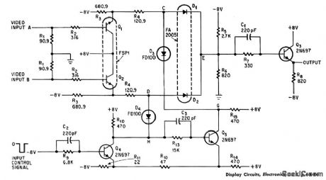
Electronic switch samples two video signals and modulates crt beam so both waveforms appear simultaneously on screen. Matched diodes D1 and D2 serve as switches for the positive 2-v video signals.-A. E. Popodi,Reliable Repertoire Of Display Circuits, Electronics 38:2, p 60-66. (View)
View full Circuit Diagram | Comments | Reading(1008)
| Pages:38/72 At 202122232425262728293031323334353637383940Under 20 |
Circuit Categories
power supply circuit
Amplifier Circuit
Basic Circuit
LED and Light Circuit
Sensor Circuit
Signal Processing
Electrical Equipment Circuit
Control Circuit
Remote Control Circuit
A/D-D/A Converter Circuit
Audio Circuit
Measuring and Test Circuit
Communication Circuit
Computer-Related Circuit
555 Circuit
Automotive Circuit
Repairing Circuit