
LED and Light Circuit
Index 27
Two alternating flashing LED light controlled by digital IC
Published:2011/11/7 20:34:00 Author:Ecco | Keyword: Two , alternating flashing , LED light , digital IC
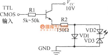
The chart shows the TTL or CMOS digital integrated circuits controlling circuit, and it uses the transistor to drive two LED lights flashing alternately. Different supply voltage can be used to change the R's value and the VD3 regulation to meet the alternately flashing requirements.
(View)
View full Circuit Diagram | Comments | Reading(1768)
The flashing LED controlled by digital IC
Published:2011/11/7 20:35:00 Author:Ecco | Keyword: flashing LED , digital IC
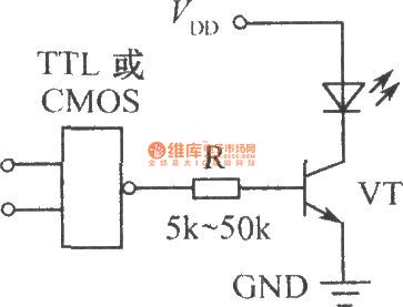
Digital integrated circuits can be TTL or CMOS circuits , and VT uses the general NPN low power tube.
(View)
View full Circuit Diagram | Comments | Reading(1170)
TTL LED driver circuit
Published:2011/11/3 3:37:00 Author:Ecco | Keyword: TTL LED driver
View full Circuit Diagram | Comments | Reading(1440)
LED driver circuit with CMOS OPAMP
Published:2011/11/3 3:37:00 Author:Ecco | Keyword: LED driver , CMOS OPAMP
View full Circuit Diagram | Comments | Reading(1635)
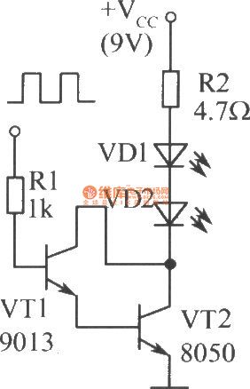
The driver circuit diagram of two infrared light-emitting diodes
Published:2011/9/26 2:23:00 Author:Rebekka | Keyword: driver circuit, light-emitting diode
View full Circuit Diagram | Comments | Reading(963)
IR remote control dimmer light circuit diagram
Published:2011/9/27 1:50:00 Author:Rebekka | Keyword: IR remote control dimmer light
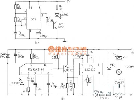
(a) is infrared emission circuit diagram. NE555 circuit generates a 40kHz pulse which is sent by the infrared emission control SE303 after beingamplified by VT. (b) is remote receiver and infrared dimming circuit composed of the KA2184. LS7232 is an integrated dimming circuit.
(View)
View full Circuit Diagram | Comments | Reading(4524)
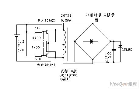
LED boost pressure driver circuit diagram
Published:2011/9/15 22:50:00 Author:Rebekka | Keyword: LED , boost pressure driver
View full Circuit Diagram | Comments | Reading(1566)
Emergency lighting circuit diagram 02
Published:2011/10/17 2:31:00 Author:Ecco | Keyword: Emergency lighting
View full Circuit Diagram | Comments | Reading(2417)
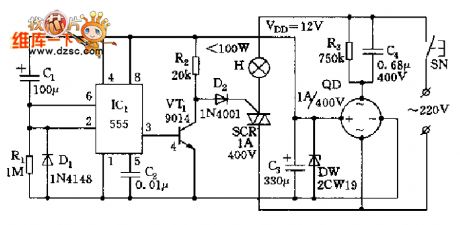
Delay energy-saving lighting circuit diagram
Published:2011/10/14 3:09:00 Author:Ecco | Keyword: Delay energy-saving lighting
View full Circuit Diagram | Comments | Reading(2411)
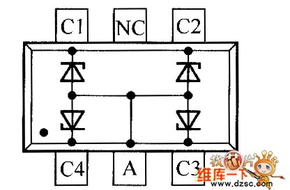
Crystal diode QZX3636C5V6 internal circuit diagram
Published:2011/9/15 2:04:00 Author:Rebekka | Keyword: Crystal diode, internal circuit
View full Circuit Diagram | Comments | Reading(857)
220v led indicator light circuit diagram
Published:2011/9/14 22:40:00 Author:Rebekka | Keyword: led indicator light
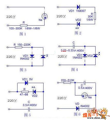
Figure 1 shows the circuit, whichhas only two components. R selects 1/6--1/8W carbon resister or metal film resistor, the resistance is betweenthe 1 - 300K. Ne is a neon bulb. It also uses the neon bulb in ordinary fluorescent starter. If you want to use 60V small neon bulb that is able to start neon bulb. The model is NNH-616 type, resistor R uses 270K 1 / 6W metal film resistor. Led light circuit is shown as the chart.
(View)
View full Circuit Diagram | Comments | Reading(14470)
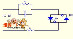
LED mains supply indicating circuit diagram
Published:2011/8/3 2:34:00 Author:Ecco | Keyword: LED , mains supply indicating
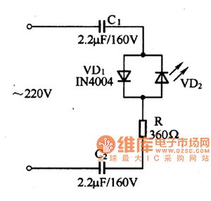
C1 and C2 in the circuit play the role of ballast and buck, andR is used for obstructing the transient inrush current. The circuit has low power consumption, reliable advantages, and it is suitable for electronic equipment as the instructions for mains supply.
(View)
View full Circuit Diagram | Comments | Reading(1850)
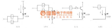
The driver circuit diagram of the voltage LED
Published:2011/8/3 2:35:00 Author:Ecco | Keyword: driver circuit, voltage LED
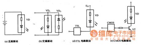
Voltage LED is convenient to use, but we should pay attention to the drive circuit's forms and ensure that the positive and negative tubes may not reversed; it must be used at rated voltage. Figure 1 shows four typical driven modes for reference.
(View)
View full Circuit Diagram | Comments | Reading(1002)
High power led drive reduction voltage regulator circuit diagram
Published:2011/8/22 22:31:00 Author:Rebekka | Keyword: High power , led driver , reduction voltage regulator
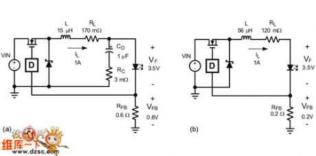
The input voltage in the whole series or series-parallel LED system is higher than the the maximum forward voltage, the best option is the standard power buck regulator topology. Because it has the output sensor, andit is ideal for constant current drive.
In the three standard DC-DC converters(buck, boost and buck - boost), only the buck converter LED driver average load current or IF is equal average inductor current. No matter which controlling method you use, in fact, the output current will not have transient change in any part of the switching loop. This makes it easier to convert the constant voltage source to constant current source. To be more specific, many step-down converters based on constant current circuit can run without output capacitor.
(View)
View full Circuit Diagram | Comments | Reading(1750)
SS0604 Touching stepping dimmer circuit diagram
Published:2011/8/9 20:16:00 Author:Ecco | Keyword: Touching stepping dimmer
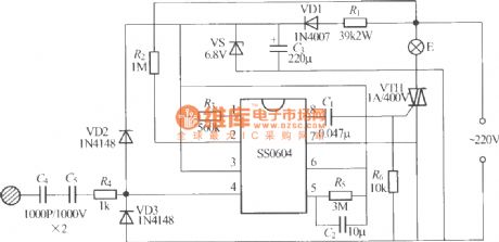
The five-speed four-step touching stepping dimmer shown as the chart is composed of the SS0604 integrated circuit, and touching the M repeatedly, the lamp brightness of E will changein the cycle of low, medium, medium to high, the brightest, turning off ... for the user to select.
(View)
View full Circuit Diagram | Comments | Reading(1235)
The LED driver circuit diagram
Published:2011/9/18 21:08:00 Author:Ecco | Keyword: LED driver
View full Circuit Diagram | Comments | Reading(1201)
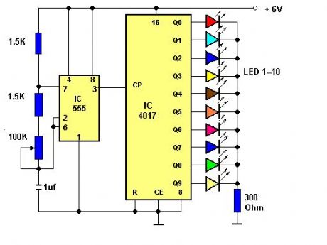
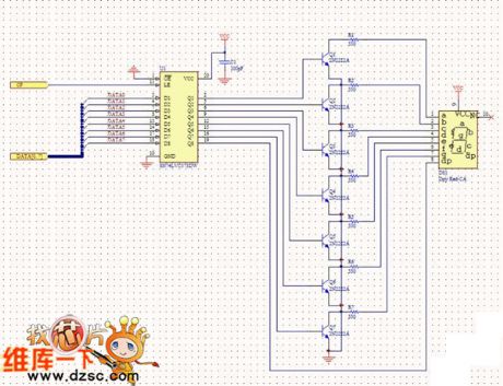
Ten-road chasing flashing circuit
Published:2011/9/12 21:08:00 Author:Ecco | Keyword: Ten-road chasing flashing
View full Circuit Diagram | Comments | Reading(2377)
Emergency light circuit diagram 01
Published:2011/9/9 2:43:00 Author:Ecco | Keyword: Emergency light
View full Circuit Diagram | Comments | Reading(1677)
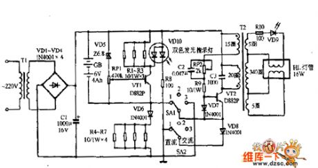
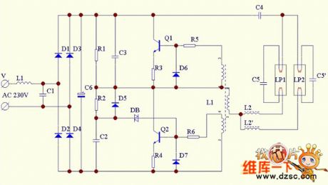
Double-barrelled energy-saving lamp circuit diagram
Published:2011/9/9 2:05:00 Author:Ecco | Keyword: Double-barrelled , energy-saving lamp
View full Circuit Diagram | Comments | Reading(4314)
8-segment LED driver circuit diagram
Published:2011/9/2 1:04:00 Author:Ecco | Keyword: 8-segment LED driver
View full Circuit Diagram | Comments | Reading(1733)
| Pages:27/72 At 202122232425262728293031323334353637383940Under 20 |
Circuit Categories
power supply circuit
Amplifier Circuit
Basic Circuit
LED and Light Circuit
Sensor Circuit
Signal Processing
Electrical Equipment Circuit
Control Circuit
Remote Control Circuit
A/D-D/A Converter Circuit
Audio Circuit
Measuring and Test Circuit
Communication Circuit
Computer-Related Circuit
555 Circuit
Automotive Circuit
Repairing Circuit