
LED and Light Circuit
Index 31
HM9902 touching two-state dimmer circuit
Published:2011/8/22 2:37:00 Author:Ecco | Keyword: touching two-state dimmer
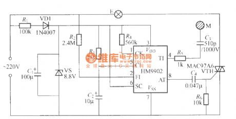
The touching lamp switch circuit made by HM9902 integrated circuit is shown as the chart, and touching M repeatedly, the light bulb E will be lit in the cycle of: light → off → light → off in order to achieve touching on / off action.
(View)
View full Circuit Diagram | Comments | Reading(1999)
The typical application circuit of 5G169 audio lantern control IC
Published:2011/8/8 20:28:00 Author:Ecco | Keyword: typical application circuit, audio lantern , control IC
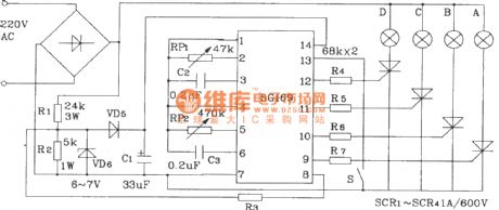
5G169 is the four ways of lights control IC with brightness being slowing. Switch S is the lantern light string loop mode (positive / anti) selector switch, and it is in positive forward cycle when open it and reverse cycle when close it, and RP1, RP2 are used to change the external RC value of Psi ~ vs3 and SA1 ~ SA3. As 5G169 has no audio signal gN-step control, it generally applies to density decorative lights, advertising lights, disco lights, etc., and sound and light can not be synchronized. For synchronization, the audio signal is rectified, coupled and enlarged and then sent to pin 1, pin 2 or pin 4, pin 5 of 5G169. HFC55 is an 8-way lights control IC.
(View)
View full Circuit Diagram | Comments | Reading(837)
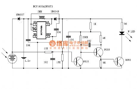
Solar night light
Published:2011/8/23 2:08:00 Author:Ecco | Keyword: Solar night light
View full Circuit Diagram | Comments | Reading(1864)
LT1932 white LED driver circuit diagram
Published:2011/8/22 21:36:00 Author:Ecco | Keyword: white LED driver
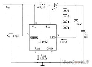
Linear Technology Corporation designs LT1932 boost DC / DC converter in order to provide the high-efficient constant drive current for white LED backlight. In order to obtain the best brightness matching, LT1932 uses drive white LED series way to protect all the series of white LED current to be matched and achieve the consistency of white LED brightness. The white LED backlight driver composed of LT1932 has conversion efficiency in generally 15% to 80%.
(View)
View full Circuit Diagram | Comments | Reading(2127)
MAX1576 White LED driver circuit diagram
Published:2011/8/12 2:06:00 Author:Lucas | Keyword: White LED driver
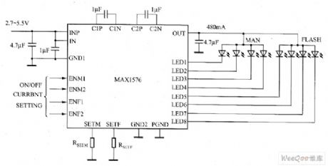
MAX1576 charge pump can drive eight white LEDs with a constant current regulation in order to achieve uniform light intensity. It can drive each group of (LED1 ~ LED4) white LED with 30mA current for backlighting. MAX1576 can achieve high efficiency in the whole operating voltage range of one lithium-ion battery. MAXl576 has lMHz fixed switching frequency, so it only uses few external components, and it also has low EMI and low input ripple. MAX1576 uses two external resistors to set the master flash white LED and white LED's largest (100%) current.
(View)
View full Circuit Diagram | Comments | Reading(931)
MAX1570 white LED driver circuit diagram
Published:2011/8/12 1:20:00 Author:Lucas | Keyword: white LED driver

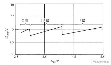
MAX1570 is 1 times voltage-multiplying mode, 1.5 times voltage-multiplying high-efficiency charge pump, which can drive up to five constant current white LEDs and get uniform brightness, and maintain the highest efficiency in the whole Li-Ion battery voltage range. MAX1570's fixed frequency is 1MHz, and it can select small external components. The optimized current regulation structure can ensure low EMI and low input ripple. It uses an external resistor to set full amount white LED current of MAX1570. Pulse-width modulation (PWM) signal can also be used to adjust the brightness of white LED.
(View)
View full Circuit Diagram | Comments | Reading(1022)
MAX1573 white LED driver circuit diagram
Published:2011/8/12 3:09:00 Author:Lucas | Keyword: white LED driver
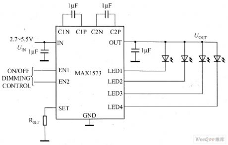
The main technical characteristics of MAX1573 charge pump are as follow: ① MAX1573 uses a tiny chip-scale (UCSP) package (4 × 4-bump, 2.1mm × 2.1mm × 0.6mm) and 16-pin thin QFN package (4mm × 4mm). ②it has proprietary adaptive 1x mode, 1.5x mode. ③ conversion efficiency (PLEDS / PBAT) is up to 92%. ④ the white LED current matching accuracy is 0.2%. ⑤ 28mA drive capability. ⑥ low input ripple and EMI. ⑦ without limiting resistor. ⑧ digital logic or PWM brightness control. ⑨ 0.1μA low shutdown current. ⑩ 2.7 ~ 5.5V input voltage range.
(View)
View full Circuit Diagram | Comments | Reading(1066)
MAX8607 white LED driver circuit diagram
Published:2011/8/15 20:23:00 Author: | Keyword: white LED driver
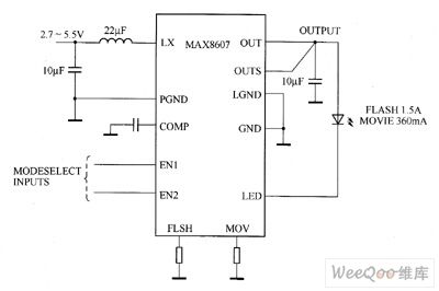
MAX8607 integrates a 1MHz PWM boost converter, 1.5A low dropout (LDO) current regulator, and logic control circuit, and it is suitable for small-size white LED flash design. MAX8607's two logic inputs control has four modes: ① shutdown modewith quiescent current decreasing to 0.1μA (typ). ② projection mode which provides 360mA continuous white light with LED current. ③ flash mode provides short 1.5A White LED current. ④ disk model provides +5 V external power supply (up to 1A) and the 80mA constant current for white LED driver.
(View)
View full Circuit Diagram | Comments | Reading(982)
MAX8595Z/MAX8596Z white LED driver circuit diagram
Published:2011/8/16 1:20:00 Author: | Keyword: white LED driver
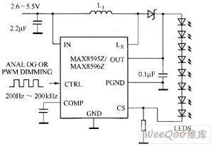
MAX8595Z/MAX8596Z's main technical characteristics are as follow. ① It uses 25mA current to drive eight white LEDs, and the temperature derating function allows less white LEDs to achieve the same brightness (MAX8596Z). ② it has 2.6 ~ 5.5V input voltage range, 12mVp-p low input ripple, and s direct PWM internal filter. ③ it has 86% efficiency (PLED / PIN). ④ it has flexible brightness control, 1.7% current regulation accuracy. ⑤ it has 1MHz PWM switching frequency, 0.1μF output capacitor. ⑥ it has soft-start, eliminate inrush current, and output overvoltage protection functions. ⑦ it has 0.3μA shutdown current.
(View)
View full Circuit Diagram | Comments | Reading(880)
LC40159 white LED driver circuit diagram
Published:2011/8/12 1:13:00 Author:Lucas | Keyword: white LED driver
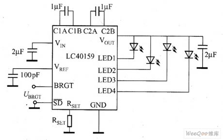
VIN side in the figure shows the input voltage of the power supply, and input voltage range is 2.7 ~ 5.5V; VREF side is the internal reference voltage, SD side is the enable signal input end, when it is input H signal, LED begins to glow; when it is input L signal, LED turns off. RSET side have set the peripheral resistor which can generate a constant current. VOUT terminal is the output end of the boost circuit, and it is connected with white LED cathode, because the converter output voltage VOUT can be synchronized with the oscillator circuit fluctuates, the VOUT terminal can be connected output capacitor in parallel to suppress fluctuations of the output voltage.
(View)
View full Circuit Diagram | Comments | Reading(962)
SP7616/SP7615 LED driver circuit diagram
Published:2011/8/12 2:14:00 Author:Lucas | Keyword: LED driver


SP7616 is the 4-channel constant-current linear white LED driver with operating voltage in 4.5 ~ 30V, and each channel supports the maximum of ω irregular current. SP7616 contains current-matching circuit, which allows the current difference between each channel to be less than 1.5%. SP7616/SP7615's typical application circuit is shown in Figure 1, each channel of SP7616 supports 60mA current and SP7615 supports 126mA current. In the SP7616 typical application circuit shown in Figure (a), if DIN (N × UF + UDROP), then the current flowing through the 4-channel white LED is constant and matched.
(View)
View full Circuit Diagram | Comments | Reading(1752)
LM3354/LM2792 white LED driver circuit diagram
Published:2011/8/12 2:22:00 Author:Lucas | Keyword: white LED driver
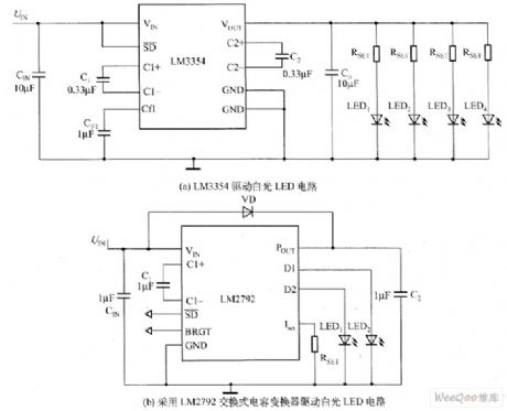
Charge pump white LED driver circuit is shown as the chart. Figure 1 (a) is the LM3354 charge pump white LED driver circuit with voltage regulation output function, and it can output 4.1V stable voltage. LM3354 charge pump input voltage range is 2.5 ~ 5.5V, and the output voltage range can be chosen from nominal values. LM3354 is used as white LED driver, which can select 4.1V output voltage. LM3354 charge pump switching frequency is 1MHz, so you can use smaller-capacity switch capacitor; the maximum output current is 90mA, and it contains on-chip thermal protection circuit with quiescent current in 475μA, and the current is 5μA when the circuit is off.
(View)
View full Circuit Diagram | Comments | Reading(1317)
CAT3200/CAT3200-5 white LED driver circuit diagram
Published:2011/8/12 2:36:00 Author:Lucas | Keyword: white LED driver
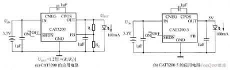
CAT3200 and CAT3200-5 are the switched-capacitor boost converter, which can output low-noise adjustable voltage. CAT3200-5's fixed output voltage is 5V. CAT3200 can use an external resistor to make the output voltage be adjustable. Their frequency is fixed at 2MHz 1μF, and the charge pump allows to use small ceramic capacitors, and wide input supply voltage range (2.7 ~ 4.5V) supports the maximum 100mA output load that allows the device ideal for battery-powered electronic device. Their shutdown control input allows the device to enter power-down mode, which allows the supply current to be less than 1μA.
(View)
View full Circuit Diagram | Comments | Reading(873)
CAT3604 white LED driver circuit diagram
Published:2011/8/12 2:41:00 Author:Lucas | Keyword: white LED driver
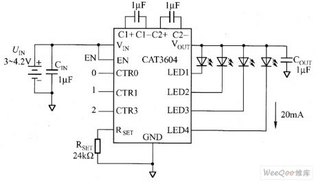
CAT3604 is the charge pump which works in 1x, 1.5x mode, and adjusting the current of each white LED pin (it has total four white LED pins) can regulate the brightness uniformity. CAT3604 work in a fixed frequency of 1MHz, it uses low-value ceramic capacitors. The enable input pin can make CAT3604 enter the power-down mode with input quiescent current which almost zero . CAT3604 can drive parallel white LEDs to provide tightly matched regulated current. The external resistor RSET controls the output current. CAT3604 is suitable for single-cell lithium-ion battery-powered portable electronic devices.
(View)
View full Circuit Diagram | Comments | Reading(878)
MAX1561/MAX1599 white LED driver circuit diagram
Published:2011/8/12 3:05:00 Author:Lucas | Keyword: white LED driver
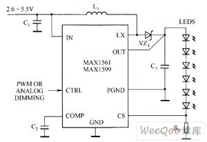
MAX1561/MAX1599 contains high-voltage, low RDS-ON N-channel MOSFET switch, which provides high conversion efficiency and extends battery life. Dual-mode input provides a simple brightness adjustment and switching control. MAX1561's 1MHz (MAX1599 to 500kHz) high-speed, current-mode pulse-width modulation (PWM) architecture allows for small input and output capacitors and inductors, and to minimize the ripple on input power (battery). Programmable soft-start function can eliminate inrush current during startup.
(View)
View full Circuit Diagram | Comments | Reading(1368)
MAX1578/MAX1579 white LED driver circuit diagram
Published:2011/8/11 4:22:00 Author:Lucas | Keyword: white LED driver
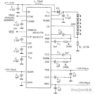
MAX1578/MAX1579 offer 4-way adjustable output, which can provide voltage for small active-matrix TFT-LCD display in portable electronic devices, and each device contains three charge pumps for LCD bias power and a boost converter, this converter can drive eight white LEDs for the backlight configuration. MAX1578/MAX1579 input voltage range is 2.7 ~ 5.5V. MAX1578 can adjust constant white LED current in the whole temperature range. MAX1579 has a cooling function to avoid to drive white LEDs in too high temperature environment.
(View)
View full Circuit Diagram | Comments | Reading(1311)
MAX1583 white LED driver circuit diagram
Published:2011/8/11 3:41:00 Author:Lucas | Keyword: white LED driver

MAX1583 boost converter can drive five white LEDs by constant current, and it provides camera flash driver for mobile phone, PDA, DSC, and other portable electronic devices. MAX1583 includes a 24V boost converter and a high-voltage LD0 current regulator to achieve high efficiency and extend battery life. Its two logic inputs can be used to select the following four modes: shutdown mode, high efficiency, continuous flash movie mode, precharge mode, flash mode. MAX1583 uses the 10-pin 3mm × 3mm TDFN package (the maximum height is 0.8mm).
(View)
View full Circuit Diagram | Comments | Reading(1216)
MAX1553/MAX1554 white LED driver circuit diagram
Published:2011/8/11 4:13:00 Author:Lucas | Keyword: white LED driver

MAX1553/MAX1554 can drive white LEDs in constant current, so it can provide high-efficiency backlight for mobile phone, PDA and other portable electronic devices. MAX1553/MAX1554 contains 40V, low RDS-ON, N-channel M0SFET switch, which greatly improves the conversion efficiency and extends battery life. MAX1553 can drive 2 to 6 white LEDs to provide 480mA current limiting; the MAX1554 can drive 10 white LEDs to provides 970mA current limiting. MAX1553/MAX1554 IC provides two simple brightness adjustment methods of single analog and PWM.
(View)
View full Circuit Diagram | Comments | Reading(1009)
MAX16803 white LED driver circuit diagram
Published:2011/8/11 3:51:00 Author:Lucas | Keyword: white LED driver
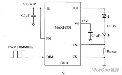
MAX16803 current regulator's input voltage range is 6.5 ~ 40V, which can provide 350mA total current for driving one or more strings of high brightness white LEDs. MAX16803 output current value can be set by an external galvanometer resistor connecting with white LED in series. It allows a wide range of PWM to adjust brightness by brightness control input terminal, and the wave shaping circuit reduces EMI, the differential current detection improves noise immunity. MAX16803 is ideal for high-voltage input applications, the built-in regulator can reduce external components' number and provide ± 3.5% output current accuracy.
(View)
View full Circuit Diagram | Comments | Reading(1065)
EL7516 white LED driver circuit diagram
Published:2011/8/11 4:03:00 Author:Lucas | Keyword: white LED driver
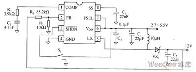
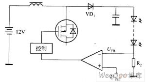
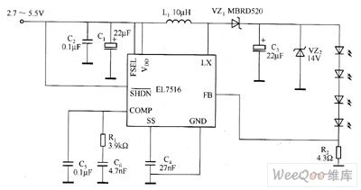
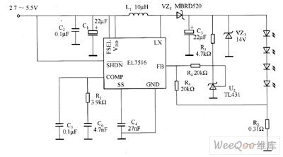
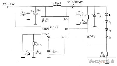
EL7516 is a typical step-up chip, which works at 1.2MHz fixed-frequency PWM mode, and it contains an 1.5A, 200mΩ MOSFET. Figure 1 shows the typical application circuit of EL7516. The DC / DC boost effect can change the 2.7 ~ 5.5V input voltage into 12V constant output voltage. It is similar to the general PWM control chip, the FB-pin sets the output voltage by the value of R1, R2 resistors. It is easy to change EL7516's constant pressure lines to constant current lines by driving white LED. Standard LED driver diagram is shown in Figure 2, as long as to change R2 in Figure 2, the white LED current is adjusted.
(View)
View full Circuit Diagram | Comments | Reading(1298)
| Pages:31/72 At 202122232425262728293031323334353637383940Under 20 |
Circuit Categories
power supply circuit
Amplifier Circuit
Basic Circuit
LED and Light Circuit
Sensor Circuit
Signal Processing
Electrical Equipment Circuit
Control Circuit
Remote Control Circuit
A/D-D/A Converter Circuit
Audio Circuit
Measuring and Test Circuit
Communication Circuit
Computer-Related Circuit
555 Circuit
Automotive Circuit
Repairing Circuit