
LED and Light Circuit
Index 28
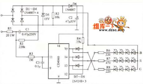
Color light circuit diagram
Published:2011/9/14 2:39:00 Author:Ecco | Keyword: Color light
View full Circuit Diagram | Comments | Reading(1297)
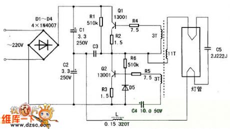
High-brightness white led light circuit diagram
Published:2011/9/14 3:03:00 Author:Ecco | Keyword: High-brightness, white led light
View full Circuit Diagram | Comments | Reading(1931)
MAX157/MAX1577Z charger-pump drive white light LED
Published:2011/9/14 21:07:00 Author:leo | Keyword: charger-pump, white light LED
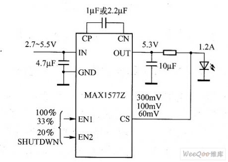
MAX157/MAX1577Z charger-pump is used to drive high power white light LED, for example, camera flash. Its maximum current is 1.2A and minimum current is 800 mA. Even if its input voltage and current are super low, its low resistance will allow it has a high brightness of flash. It adopts outer resistance set system to control the current. Max1577Z has a fixed output voltage of 5.1 V and MAX1577Y can output voltage of 3.4 V, 4.6 V or 5.1 V. (View)
View full Circuit Diagram | Comments | Reading(1041)
MAX1576 high-power white LED driver circuit diagram
Published:2011/9/12 19:58:00 Author:Lucas | Keyword: high-power, white LED driver
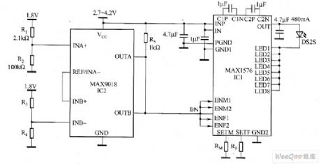
The circuit includes the charge pump regulator (IC1) which is suitable for camera flash applications, and the device can provide current regulation for 8 white LEDs. The LED1 ~ LED8 connected in parallel can provide 480mA current for a single IW, LUXE * tar high-power white LED module. When open drain input (ENM1/ENM2 or ENF1/ENF2) is pulled to ground, IC1 gets into shutdown mode. The circuit uses a thermistor (R2) and dual open-drain comparator (IC2) with internal reference to constitute a compact space and very low-cost thermal shutdown circuit.
(View)
View full Circuit Diagram | Comments | Reading(1436)
The LED constant-current driver circuit based on LM2734
Published:2011/8/20 2:12:00 Author: | Keyword: constant-current driver

LM2734 is 1A buck regulator.Based on the LM2734 constant-current driver circuit (shown as above),the circuit uses LM321 operational amplifier to obtain the voltage of the sampling resistor Rset,then combines the other resistor and capacitor to form a complete,high-efficiency power LED constant current driver circuit.In actual use,some LED constant current driver circuit can get feedback voltage directly from the sampling resistor,it is shown as figure.
(View)
View full Circuit Diagram | Comments | Reading(2669)
The drive LED typical application circuit
Published:2011/8/21 22:32:00 Author: | Keyword: drive LED, typical application
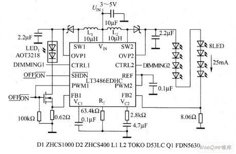
The dual-channel booster LT3486 produced by Linear Technology can drive 16 white light LEDs with a constant current(each channel has 8 serial LEDs), it can not only provide with PWM dimming, but also maintain the light color of the LED. It is fitted in portable electric equipment, car screens and other situations. LT3486 dims by controlling the working period of PWM, and the dimming range is 1000:1. It keeps the even LED brightness by the current mode and solid frequency.
(View)
View full Circuit Diagram | Comments | Reading(1140)
CAT3606 white LED driver circuit diagram
Published:2011/8/23 22:23:00 Author:Lucas | Keyword: white LED driver
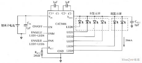
CAT3606 and lithium-ion battery system are used in conjunction to get 90% efficiency, the current of each output channel can be adjusted to match up to 6 white LEDs and make consistency brightness of control panel. Its unique fractional charge pump technology can automatically switch 1x mode to 1.5x mode to ensure that the entire life of the battery remains flicker-free white LED current. CAT3606 uses 16-pin 4mm × 4mm QFN package with a maximum height of 0.8mm, the product uses green packaging materials without halogen and lead, and it can reach R0HS requirements.
(View)
View full Circuit Diagram | Comments | Reading(950)
MAX7316 white LED driver circuit diagram
Published:2011/8/23 22:23:00 Author:Lucas | Keyword: white LED driver
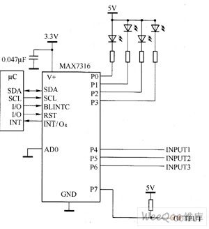
MAX7316's main technical characteristics are as follow. ① 400kbps, 2-wire Serial Interface, 5.5V voltage tolerance. ② working voltage is 2 ~ 3.6V. ③ 8-bit PWM White LED brightness control, global brightness control 16 with additional 16 independent brightness control. ④ two-phase flashing white LED. ⑤ it has 5.5V input voltage protection. RST input clears the serial port status, and restore it to power-on default state. ⑥ each high port output current is 50mA (max); output voltage is 5.5V, open-drain. ⑦ it supports hot insertion. ⑧ low standby current is typically 1.2μA, and the maximum value is 3.3μA.
(View)
View full Circuit Diagram | Comments | Reading(1535)
MAX16809/MAX16810 white LED driver circuit diagram
Published:2011/8/23 22:23:00 Author:Lucas | Keyword: white LED driver
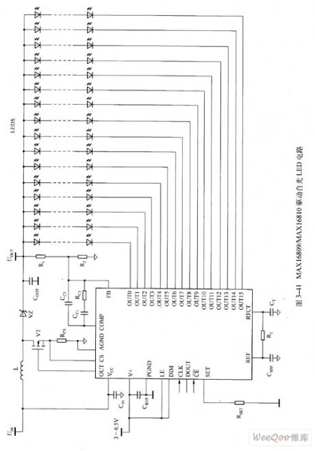
MAX16809/MAX16810's main technical characteristics are as follow. ① it has 16 constant current output channels (each channel is up to 55mA), each output has ± 3% current matching. ② all channels uses a single resistor to set the white LED current. ③ parallel output channels can provide greater white LED series branch current. ④ continuous rated output voltage is 36V. ⑤ output enable pin is used for PWM dimming (frequency is up to 30kHz). ⑥ it has white LED open detection circuit and watchdog (MAX16810). ⑦ it has wide dimming ratio, which can be up to 5000:1.
(View)
View full Circuit Diagram | Comments | Reading(1062)
MAX16807/MAX16808 white LED driver circuit diagram
Published:2011/8/23 22:22:00 Author:Lucas | Keyword: white LED driver
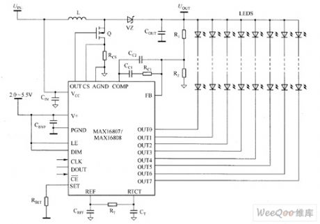
MAX16807/MAX16808's main technical characteristics are as follow. ① it has 8 constant current output channels (each channel current is up to 55mA). ② the current matching accuracy of output end is ± 3%. ③ parallel channels make each branch have a greater series white LED current. ④ continuous rated output voltage is 36V. ⑤ output enable pin is used for PWM brightness adjustment (frequency is up to 30kHz). ⑥ it can use a single resistor to set the white LED current for all channels. ⑦ wide brightness ratio is up to 5000:1. ⑧ low current detection reference (300mV) could achieve high efficiency.
(View)
View full Circuit Diagram | Comments | Reading(1144)
MAX8901A/MAX8901B white LED driver circuit diagram
Published:2011/8/23 22:22:00 Author:Lucas | Keyword: white LED driver
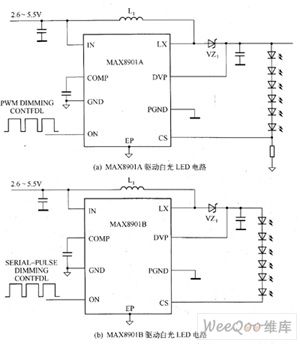
MAX8901A/MAX8901B boost converter is capable of driving 2 to 6 series white LEDs with constant current, and it can provide white LED drivers with uniform brightness and LCD backlighting for mobile phone, PDA and other handheld devices. MIAX8901A/MAX8901B's main technical characteristics are as follow. ① efficiency is up to 91%. ②it has 2.6 ~ 5.5V input voltage range. ③ it has fixed frequency mode. ④it has input undervoltage lockout, input overvoltage lockout, white LED overvoltage protection function (typical value is 25V). ⑤ typical shutdown current is 0.01μA. It has no white LED current under shutdown mode.
(View)
View full Circuit Diagram | Comments | Reading(1508)
MIC2298 LED driver circuit diagram
Published:2011/9/8 3:38:00 Author:Lucas | Keyword: LED driver
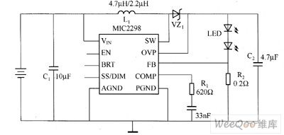
Micrellnc introduces the industry's smallest and most powerful LED driver MIC2298 for portable electronic devices. The device is the 7W efficient boost DC / DC converter, and it uses small 3mm × 3mm MLF packaging. MIC2298 is designed for mobile phones, personal digital assistant (PDA) and digital camera's flash and torch lighting applications. MIC2298 can ensure 3.5A conversion current. The operating input voltage range is 2.5 ~ 10V.
(View)
View full Circuit Diagram | Comments | Reading(1963)
MAX16831 White LED driver circuit diagram
Published:2011/8/23 22:22:00 Author:Lucas | Keyword: White LED driver
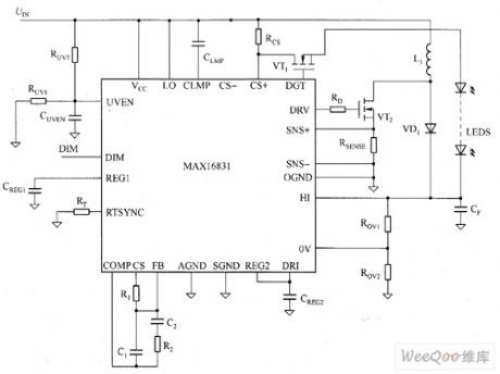
MAX16831's main technical characteristics are as follow. ① Wide Input Range: 6 ~ 76V, cold start working can be up 5.5V. ② integrated white LED current sense differential amplifier. ③ it can drive N-channel MOSFET with floating light drive capability. ④ white LED current accuracy: 5%. ⑤ 200Hz-chip ramp generator can be synchronized to an external PWM dimming signal. ⑥ its sync / programmable switching frequency is 125 ~ 600kHz. ⑦ iy has output over-voltage, open load, white LED short circuit, overheat protection. ⑧ enable / shutdown input, turn-off current is less than 45μA.
(View)
View full Circuit Diagram | Comments | Reading(977)
MAX6965 White LED driver circuit diagram
Published:2011/8/23 22:22:00 Author:Lucas | Keyword: White LED driver
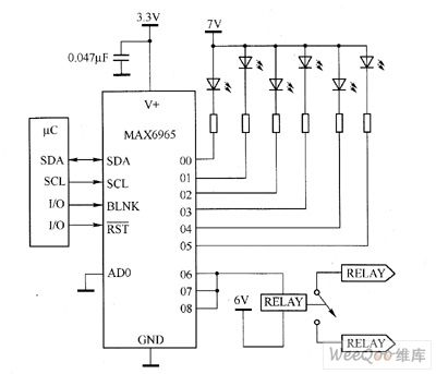
MAX6965's main technical characteristics are as follow. ① 400kbps, 2-wire Serial Interface, 5.5V voltage tolerance. ② 2 ~ 3.6V operating voltage. ③ 8-bit PWM White LED brightness control. ④ global 16 brightness control, additional 16 independent brightness control. ⑤ Rated Output 7V, open-drain. ⑥ two-phase flashing white LED. ⑦ high port output current, each port's output current is 50mA (max). ⑧ when it is in RST input clear port status, port status returns to power-on default state. ⑨ it supports hot insertion. ⑩ low standby current is typical 1.2μA, and the maximum value is 3.3μA.
(View)
View full Circuit Diagram | Comments | Reading(1238)
SR03x driving LED circuit diagram
Published:2011/8/23 22:22:00 Author:Lucas | Keyword: driving LED
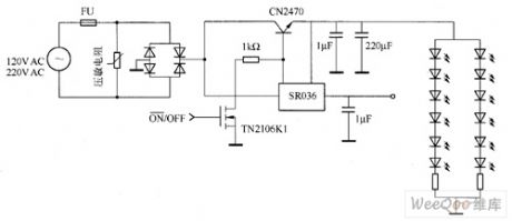
SR03x is the dual-output DC / DC power management IC without any magnetic components, the typical application circuit is shown as the figure. SR036 and SR037 are SR03x series of products produced by SUPERTEX company, and in the figure, SR03x series do not need any transformer, inductor, or high input capacitor. At the same time, its working principle is simple: SR03x input end is designed to access 120μV, 230V rectified output directly. SR03x series of IC requires only minimal external components.
(View)
View full Circuit Diagram | Comments | Reading(2303)
MAX7306/MAX7307 white LED driver circuit diagram
Published:2011/8/23 22:22:00 Author:Lucas | Keyword: white LED driver
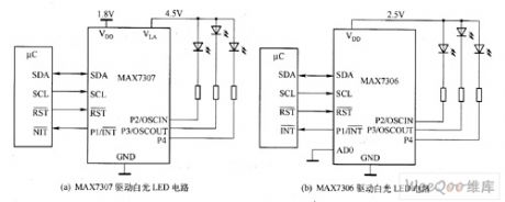
MAX7306/MAX7307's main technical characteristics are as follow. ① 1.4 ~ 5.5VI / O logic into port power (ULA). ② Power supply voltage is 1.62 ~ 3.6V. ③ It has independent 33 PWM brightness control with 15 flash control in output end, and 1kHz PWM cycle flicker-free white LED brightness control. ④ optional input debounce, input over-voltage is up to 5.5V (ULA) with interrupt output transient detection. ⑤ when it is in low-level active RST input clear port state, J will restore power-on default state. ⑥ oscillator input and output can cascade multiple devices. ⑦ low standby typical current is 0.75μA.
(View)
View full Circuit Diagram | Comments | Reading(883)
MAX7314 white LED driver circuit diagram
Published:2011/8/23 22:22:00 Author:Lucas | Keyword: white LED driver
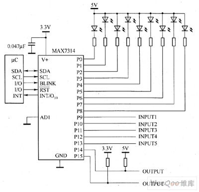
MAX7314's main technical characteristics are as follow. ① it has 400kbps, 2-wire serial interface, and the voltage is 5.5V. ② working voltage is 2 ~ 3.6V. ③ the total 8-bit PWM LED intensity control has a global 16-level brightness control with separate 16 additional brightness control, two-phase LED flashing. ④ it has Interrupt Output transition detection circuit, which can work in 5.5V open-drain output, each port's maximum output current is 50mA. ⑤ Input over-voltage protection is up to 5.5V. ⑥ operating current is typical 1.2μA, and the maximum value is 3.6μA. ⑦ it uses small 4mm × 4mm thin QFN package.
(View)
View full Circuit Diagram | Comments | Reading(928)
Adjustable speed LED flasher circuit diagram
Published:2011/8/30 20:26:00 Author:Lucas | Keyword: Adjustable speed, LED flasher
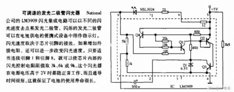
National's LM3909 flashing IC flash can light the light-emitting diode in different rates, and the flashing LED is used as indicator in the battery-powered portable devices. Flashing speed depends on the chip pin connection. If it increases an external resistor, the flashing rate can be further improved. If the connection of pin 1 and pin 8 is appropriately, you can make the chip internal controlling resistor take 3K, 6K, or 9K. The flashing device can work normally with the power supply voltage higher than 2V, but the lead time is very short, which ensures long battery life.
(View)
View full Circuit Diagram | Comments | Reading(1919)
SCR flashing LED circuit diagram
Published:2011/9/5 3:20:00 Author:Lucas | Keyword: SCR flashing LED
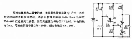
Single-junction transistor oscillator Q1 produces a series of timing pulses to trigger the SCR, then the SCR drives the 276-041 red light-emitting diode produced by Radio Shack company. When the flashing rate is 12 times per second, the circuit power consumption is 2mA. SCR model is 276-1089, ratings are 6A, 50V.
(View)
View full Circuit Diagram | Comments | Reading(1215)
Light-operated aquarium flashing light circuit diagram
Published:2011/9/7 2:33:00 Author:Lucas | Keyword: Light-operated aquarium , flashing light
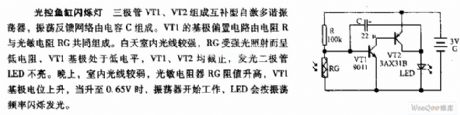
Transistors VT1, VT2 form the complementary self-excited multivibrator, and the oscillator feedback network is composed of the capacitor C. The base bias circuit of VT1 consists of resistor R and the photosensitive resistor RG. Indoor light is strong during the day, RG is exposed to strong light shows low resistance, VT1 base is in low level, VT1, VT2 are closed, light-emitting diode LED is not lit. At night, indoor light is weak, the photosensitive resistor RG is increased, VT1's base potential rises, when it rises to 0.65V, the oscillator starts to work, LED light will flash according to the oscillation frequency.
(View)
View full Circuit Diagram | Comments | Reading(1126)
| Pages:28/72 At 202122232425262728293031323334353637383940Under 20 |
Circuit Categories
power supply circuit
Amplifier Circuit
Basic Circuit
LED and Light Circuit
Sensor Circuit
Signal Processing
Electrical Equipment Circuit
Control Circuit
Remote Control Circuit
A/D-D/A Converter Circuit
Audio Circuit
Measuring and Test Circuit
Communication Circuit
Computer-Related Circuit
555 Circuit
Automotive Circuit
Repairing Circuit