
LED and Light Circuit
Index 29
The LED circuit diagram with flashing once
Published:2011/9/7 2:19:00 Author:Lucas | Keyword: LED , flashing once
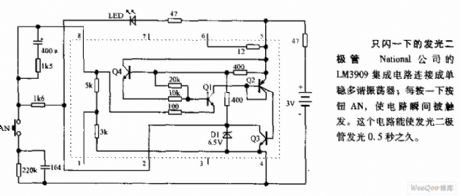
National's LM3909 integrated circuit is connected as the monostable multivibrator; clicking the button AN once will trigger the circuit at the moment. The light emitting diode circuit can falsh for 0.5s.
(View)
View full Circuit Diagram | Comments | Reading(850)
DC strobe light circuit diagram
Published:2011/9/7 2:16:00 Author:Lucas | Keyword: DC strobe light
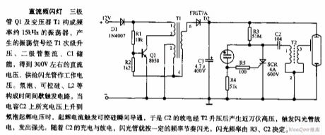
Transistor Q1 and transformer T1 form the oscillator with frequency about 15kHz, and the oscillation signal is boosted by the T1 secondary, rectified by diode, storaged by C1 to be about 300V DC voltage. Neon bulb, SCR, L2, etc. constitute a time interval trigger circuit. When the charging voltage on the capacitor C2 is up to the neon bulb starter voltage, starter current will trigger SCR to get transient conduction, so the discharge of C2 can get ten thousand volts after boosting by T2, then it will trigger the flashing tube to discharge and emit strong light. With the charge and discharge of the C2, the flashing tube will flash at a certain frequency rhythm.
(View)
View full Circuit Diagram | Comments | Reading(2665)
Quick 1.5V flashing circuit diagram
Published:2011/8/30 21:06:00 Author:Lucas | Keyword: Quick 1.5V flashing

There is an increased 1.5kΩ resistor connected between pin 4 and pin 8 of National's LM3909 IC, and it makes the flashing rate be 2 times quicker than the 300μF capacitor between pin 1 an dpin 2. Changing the connection of external leads can make the resistance of the internal RC circuit select in 3K, 6K or 9K.
(View)
View full Circuit Diagram | Comments | Reading(1134)
CAT37 White LED driver circuit diagram
Published:2011/8/25 21:06:00 Author:Lucas | Keyword: White LED driver
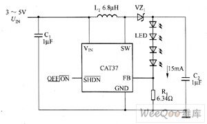
CAT37 is the DC / DC step-up converter with adjustable output current. CAT32's main technical characteristics are as follow. ① Low Quiescent Current: 0.5mA. ② it uses low-resistance (0.5Ω)and high-voltage power switch, and the power efficiency is above 80%. ③ pin configuration is compatible with LT1937. ④ adjustable output current is up to 40mA, which can drive up to four series of white LEDs. ⑤ operating frequency is 1.2MHz, and it can use an external low inductor, capacitor. ⑥ When the input voltage is as low as 2.5V, it also can work. ⑦ Shutdown current is less than 1μA. ⑧it has open load protection.
(View)
View full Circuit Diagram | Comments | Reading(889)
R1211 White LED driver circuit diagram
Published:2011/8/25 21:12:00 Author:Lucas | Keyword: White LED driver
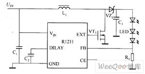
Ricoh's R1211 Series use low-power CMOS technology to produce the switching boost converters with current controlling function. The peripheral circuit is simple, it just needs an inductor, a diode, a FET and a few resistors and capacitors. The input voltage range is 2.5 ~ 5.5V, and it is suitable for single cell lithium-ion battery or ordinary dry battery power supply. The internal parts of the chip uses PWM modulation, which can produce 15V output voltage to drive 3 series white LEDs. The maximum duty cycle of R1211 is 90%. R1212 has a 1.4MHz fixed switching frequency.
(View)
View full Circuit Diagram | Comments | Reading(915)
LT3543 White LED driver circuit diagram
Published:2011/8/25 21:18:00 Author:Lucas | Keyword: White LED driver
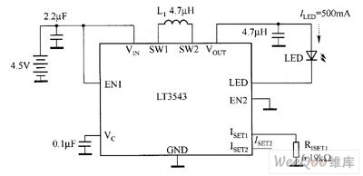
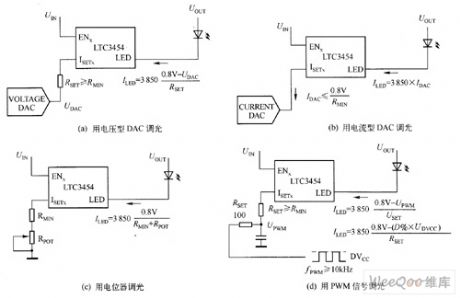
The white LED (ILED = 500mA) driver circuit composed of LT3543 is shown in Figure 1. In Figure 1, the ISET1 end is set a 6.19kΩ resistor, and EN1 is used to control the white LED turning on and off. ISET2 is vacant, and EN2 is ground. White LED in the circuit selects LUMILED company's products LXCLLW3C; inductor L1 is TOKO's A997AS-4R7M. Changing the resistor RISETI of ISET1 side can change the white LED current ILED, that can achieve the dimming purpose by changing the brightness of white LED. The white LED dimming has four methods, which are shown in Figure 2.
(View)
View full Circuit Diagram | Comments | Reading(1306)
LT3466 LED driver circuit diagram
Published:2011/8/31 20:15:00 Author:Lucas | Keyword: LED driver
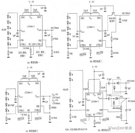
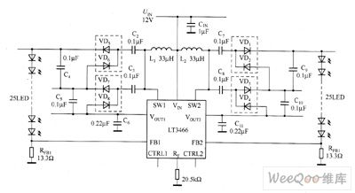
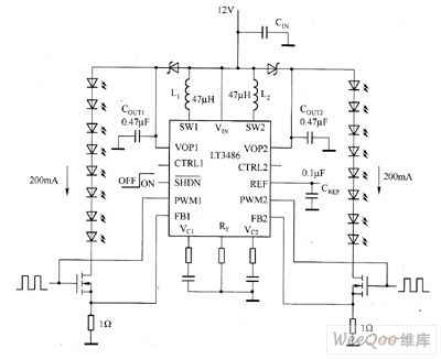
LT3466 is a dual-output full-featured step-up DC / DC converter. The two LED strings can be dimming by each CTRL pin independent control, and the internal PWM dimming system can provide PWM signal for their respective PWM pin, thus dimming range is extended to 1000:1. The LT3486's operating frequency can be set by external resistors, and their range is 200kHz ~ 2MHz. The current detection circuit has the low feedback voltage (200mV) to reduce power consumption of the current-sense resistor and improve the efficiency of the circuit, and it has LED open circuit output voltage limiter function.
(View)
View full Circuit Diagram | Comments | Reading(1822)
Traffic light alternately flashing circuit diagram
Published:2011/8/31 20:36:00 Author:Lucas | Keyword: Traffic light , alternately flashing
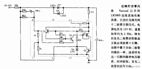
National's LM3909 is connected into relaxation oscillator, which allows two diodes with red light green light alternately flashing. Power supply is 12V, and the repetition rate is about 2.5HZ, then the anode or cathode of green light-emitting diode must be connected to pin 5, and the connection is shown in the bottom, this is because the pulse voltage of the pin is higher, time is shorter. LED models is not limited.
(View)
View full Circuit Diagram | Comments | Reading(1073)
Red and green LED flasher circuit diagram
Published:2011/8/31 20:51:00 Author:Lucas | Keyword: Red LED flasher , green LED flasher
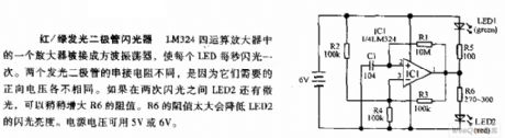
An amplifier in the LM324 quad op amp is connected as a square wave oscillator to make each LED flash once per second. Two light-emitting diode series resistors is different, because they require different forward voltages. If LED2 has low light between the two flashing interval, the resistance R6 can be slightly increased. R6 is too high to reduc LED2's flashing brightness. The supply voltage can be use 5V or 6V.
(View)
View full Circuit Diagram | Comments | Reading(1532)
CAT32 white LED driver circuit diagram
Published:2011/8/25 21:04:00 Author:Lucas | Keyword: white LED driver
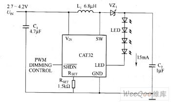
CAT32 is the DC / DC step-up converter with adjustable output current. CAT32's main technical characteristics are as follow. ① Low Quiescent Current: 0.5mA. ② it uses low-resistance (0.5Ω)and high-voltage power switch, and the power efficiency is above 80%. ③ pin configuration is compatible with LT1932. ④ adjustable output current is up to 40mA, which can drive up to four series of white LEDs. ⑤ operating frequency is 1.2MHz, and it can use an external low inductor, capacitor. ⑥ When the input voltage is as low as 2.0V, it also can work. ⑦ Shutdown current is less than 1μA. ⑧it has open load protection.
(View)
View full Circuit Diagram | Comments | Reading(1191)
CP2126 white LED driver circuit diagram
Published:2011/8/25 20:59:00 Author:Lucas | Keyword: white LED driver
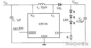
CP2126 is the boost DC / DC converter which uses constant current to drive white LED. CP2126's main technical characteristics are as follow. ① the 3.2V power supply can drive four series of white LEDs. ② high efficiency: 85% (typical value). ③ it only needs 0.22μF output capacitor. ④ stable 20V bipolar switch. ⑤ working switching frequency is 900kHz, and it can the small inductor with the height in only 1mm. ⑥ working temperature environment meets the industry-standard: -40 ~ 85 ℃. ⑦it uses flat SOT23-5L package.
(View)
View full Circuit Diagram | Comments | Reading(858)
T6321A/T6325A White LED driver circuit diagram
Published:2011/8/29 3:05:00 Author:Lucas | Keyword: White LED driver
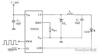
T6321A has a wide voltage input range, and conversion efficiency can reach 80%, and it has the fatures of stable work, strong anti-interference, simple circuit, thermal performance (the bottom of the IC has the cooling chip to reduce the core temperature in 10 ℃ and extend the life of the IC) and so on. T6321A's main technical characteristics are as follow. ① constant current output: 350mA. ② Input DC voltage range: 6.0 ~ 18V. ③ Package Type: SOT23-3. ④ Operating Temperature: -40 ~ +85 ℃. ⑤ Maximum soldering temperature: 260 ℃.
T6325A's main technical characteristics are as follow. ① Input Voltage: 7 ~ 24V. ② constant current output: the maximumvalue is 700mA. ③ Temperature: -40 ~ +85 ℃. ④ Maximum soldering temperature: 300 ℃.
(View)
View full Circuit Diagram | Comments | Reading(1136)
LTC3490 white LED driver circuit diagram
Published:2011/9/6 4:33:00 Author:Lucas | Keyword: white LED driver
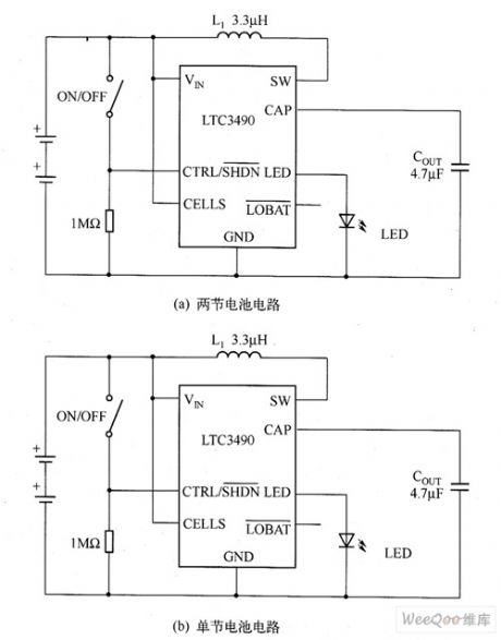
LTC3490 is a synchronous current-mode step-up converter with fixed frequency. In the two-cell application circuit, LTC3490's efficiency is up to 90%; in the application of single cell circuit, LTC3490's efficiency is higher than 70%. The Figure shows the LTC3490's two-battery circuit and single-cell circuit. In the circuit, when the output voltage is higher than 4.5V, the over-voltage detector will force the LTC3490 into shutdown mode, and over-voltage detector remains connection state, when the output voltage is down below to 4.5V, it starts the normal work.
(View)
View full Circuit Diagram | Comments | Reading(1378)
LT3436EFE high-power white LED driver circuit diagram
Published:2011/9/6 4:29:00 Author:Lucas | Keyword: high-power white LED, driver
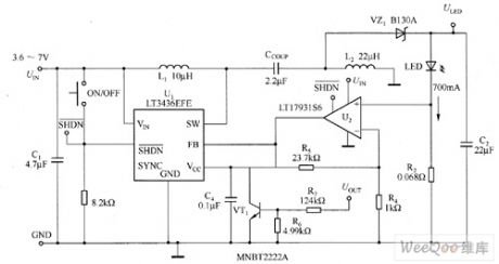
The SEPIC power white LED driver circuit with wide input voltage composed of LT3436EFE is shown as the figure, and in the wide input voltage range (3.6 ~ 7V), it can provide 700mA driver current for the LuxeonV series of white LEDs. Converter's output voltage is 6.8V, which is the LED (Model LXHL-LW6C)'s forward voltage. U1 is the high-efficient, 3A thermally enhanced LT3436EFE on-board power switch, which can simplify the regulator design and layout. It also gives the white LED driver sufficient current without overheating. U2 is the LTl7931S6 op amp with SOT-2 package.
(View)
View full Circuit Diagram | Comments | Reading(1870)
NCP5010 white LED driver circuit
Published:2011/8/29 2:37:00 Author:Lucas | Keyword: white LED driver
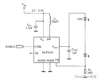
The IC integrates the rectification function, and it can provide 22V voltage, and the single resistor can be used to set the white LED current, and output power is up to 500mW, and it can drive 2 to 5 series of white LEDs. NCP5010 input voltage range is 2.7 ~ 5.5V, and the input efficiency can be up to 84% at 4.2V and 30mA, and the cut off current is 1μA with real cut, short-circuit and overvoltage protection, undervoltage cut off. In addition, due to its pulse width modulation (PWM) boost converter frequency is 1MHz, it integrates the Schottky rectifier.
(View)
View full Circuit Diagram | Comments | Reading(871)
MAX1582 LED driver circuit diagram
Published:2011/8/31 20:28:00 Author:Lucas | Keyword: LED driver
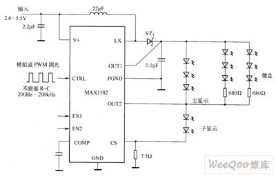
For wireless handheld devices with color display, white LED backlighting is the main backlight. White LED backlight has the features of simple circuit, high efficiency, high reliability. New generation of mobile phones generally use 3 to 4 white LEDs as the main display backlight; it uses two white LEDs for the sub-display (folding design) backlight; it uses six or more white / color LEDs for the keyboard backlight. If mobile phones integrates with cameras, it also needs at least four white LEDs for flashing, MPEG video sources. Thus, a mobile phone uses 16 white LEDs in a total.
(View)
View full Circuit Diagram | Comments | Reading(2080)
MAX16821/MAX16821A/MAX16821B/MAX16821C white LED driver circuit diagram
Published:2011/8/25 21:23:00 Author:Lucas | Keyword: white LED driver
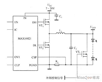
MAX16821A/MAX16821B/MAX16821C's main technical characteristics are as follow. ① 30A output current. ② it uses the average current mode control, true differential remote output detection technology. ③ 125kHz ~ 1.5MHz Programmable / synchronized switching frequency. ④ 4.75 ~ 5.5V or 7 ~ 28V input voltage range. ⑤ 0.1V/0.03V two kinds of white LED current-sense options, which allow the maximum efficiency (MAX16821B/MAX16821C). ⑥ it has no-lockout overvoltage protection output and thermal shutdown protection. ⑦ Integrated 4A Gate Driver. ⑧ low-buck mode, which can be chosen in two structures with synchronous rectification or not.
(View)
View full Circuit Diagram | Comments | Reading(1024)
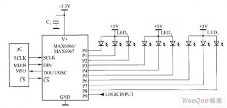
MAX6946/MAX6947 white LED driver circuit diagram
Published:2011/8/25 21:30:00 Author:Lucas | Keyword: white LED driver
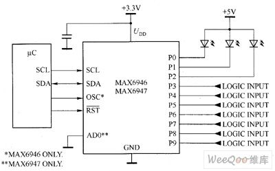
MAX6946/AX6947's main technical characteristics are as follow. ① 400kbps, 6V withstand voltage, I2C/SMBus-compatible serial interface. ② working voltage is 2.25 ~ 3.6V. ③ when the power is turned on, I / O port is implied in high impedance (it can be synchronized with the turning off of LED) state. ④ I / O port has the 7V overvoltage protection. ⑤ I / O port output type: open-drain output or open-drain logic output when voltage rating is 7V (10mA or 20mA static / PWM output can be synchronized with the LED constant current driver). ⑥ I / O ports support hot insertion. ⑦ each LED can be synchronized with the separate 8-bit PWM brightness control.
(View)
View full Circuit Diagram | Comments | Reading(1009)
LT3474 White LED driver circuit diagram
Published:2011/8/29 3:00:00 Author:Lucas | Keyword: White LED driver
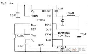
LT3474 is the step-down DC / DC converter with fixed frequency, the LED driver circuit composed of LT3474 is shown in Figure 3-58. Its internal sense resistor is mainly used to monitor the output current in order to achieve stable and accurate flowing. The device is ideal for driving high current white LED, and it can maintain high output current accuracy in 35mA ~ 1A wide current range in order to achieve a wide dimming range. The dimming range can use PWM pin and an external N-channel MOSFET to further expand and achieve 1000:1 dimming range. LT3474's switching frequency can be programmed in the range of 200kHz ~ 2MHz.
(View)
View full Circuit Diagram | Comments | Reading(1197)
MAX6966/MAX6967 white LED driver circuit diagram
Published:2011/8/25 21:34:00 Author:Lucas | Keyword: white LED driver
MAX6966's main technical characteristics are as follow. ① it has high-speed 26MHz SPI / QSPI / MICROWIRE compatible serial port. ② 2.25 ~ 3.6V operating voltage. ③ when the power is turned on, I / O port is implied to high impedance (LED turns off) state. ④ I / O port input over-voltage protection value is 7V. ⑤ it has open-drain output when I / O port output rated voltage is 7V. ⑥ I / O port output is 10mA or 20mA constant current, static / PWM or open-drain logic output. ⑦ I / O ports support hot insertion. ⑧ each outputs independent 8-bit PWM control. ⑨ it has Schmitt logic input with overvoltage protection.
(View)
View full Circuit Diagram | Comments | Reading(1754)
| Pages:29/72 At 202122232425262728293031323334353637383940Under 20 |
Circuit Categories
power supply circuit
Amplifier Circuit
Basic Circuit
LED and Light Circuit
Sensor Circuit
Signal Processing
Electrical Equipment Circuit
Control Circuit
Remote Control Circuit
A/D-D/A Converter Circuit
Audio Circuit
Measuring and Test Circuit
Communication Circuit
Computer-Related Circuit
555 Circuit
Automotive Circuit
Repairing Circuit