
LED and Light Circuit
Index 35
NUMERICAL_DISPLAY
Published:2009/7/15 21:21:00 Author:Jessie
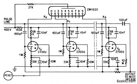
Either cold. cathode trigger tubes or transistors drive 10-digit cold-cathode indicator Tube.-M. A. Mac-Dougall, Using the Cold-Cathode Tube: Part 1, Electronics, 38:6, p 78-82. (View)
View full Circuit Diagram | Comments | Reading(1353)
VOLTAGE_DIP_INDICATOR
Published:2009/7/15 23:03:00 Author:Jessie

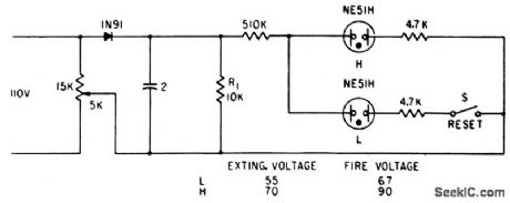
Two neon lamps in parallel, with different striking voltages, form neon latch. After circuit is activated, next line voltage dip below preset level turns on lamp L. Circuit is then disabled until reset button is pressed.-T. D. Koranye, Thyratron Monitors Line-Voltage Dips, Electronics, 34;1, p126. (View)
View full Circuit Diagram | Comments | Reading(994)
DARL_ALARM
Published:2009/7/15 22:20:00 Author:Jessie
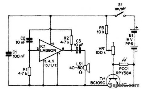
This alarm senses darkness. Photocell PCC1 is normally irradiated with light and has a low resistance. In darkness, the resistance increases, and enough bias is available to turn on Tr1, activating the oscillator circuit consisting of IC1 and associated components. This produces a tone in speaker LS1. (View)
View full Circuit Diagram | Comments | Reading(1013)
BINARY_NEONS
Published:2009/7/15 21:46:00 Author:Jessie
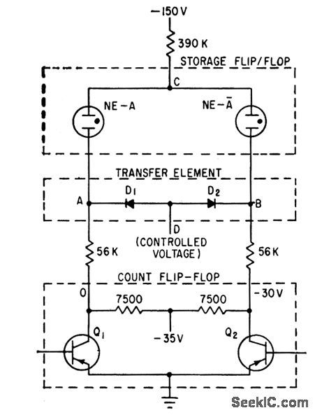
Q1 and Q2 are active elements in transistor binaries, and lamps NE-A are pre-aged neons matched with respect lo firing and running voltages. Voltage at D stores information in neon lamps.-B. H. Harrison, Photoconductive Matrix Simplifies Counter Display, Electronics, 34:51, p 28-30. (View)
View full Circuit Diagram | Comments | Reading(870)
LAMP_TYPE_INDICATOR
Published:2009/7/15 21:41:00 Author:Jessie
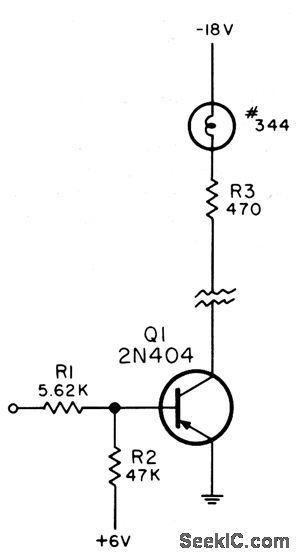
Used as indicator in digital logic circuits. Common-emitter amplifier drives type 344 lamp rated 18 ma at 12V. Can also be used to drive electromechanical indicator having the same operating power requirements. Lamp may be remotely located.-NBS, Handbook Preferred Circuits Navy Aeronautical Electronic Equipment, Vol. II, Semiconductor Device Circuits, PSC 13 (originally PC216), p 13-2. (View)
View full Circuit Diagram | Comments | Reading(801)
GAS_TUBE_READOUT
Published:2009/7/15 21:39:00 Author:Jessie
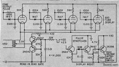
Thyratron display tubes (Kip Memolites) remain on until next input sync pulse occurs. Static delay one. shot is then triggered, to extinguish display bulbs by dropping their plate voltage below ionization point. Bulbs ore extinguished only when new input information is to be received. Used in converting up to 13 bits from Gray code to straight binary.-R. Wasserman and W. Nutting, Solid. State Digital Code-to-Code Converter, Electronics, 32:50, p 60-63. (View)
View full Circuit Diagram | Comments | Reading(970)
LAMP_READOUT_INVERSION
Published:2009/7/15 21:35:00 Author:Jessie
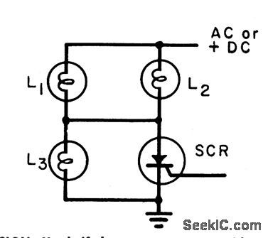
Used if lamp output is required with switch open, or if two lamp outputs ore required (one lamp coming on for switch open and the other for switch closed). All lamps are type 39, rated 6.3V at 0.36 amp. With scr off, voltage across L1 and L2 was 0.8V with 6.3V across L3, with no visible light from L1 and L2. With scr on, there is about 6.3V across L1 and L2, with no visible output from L3.-Inversion Technique for Incandescent tamp Readouts, Electronic Circuit Design Handbook, Mactier Pub. Corp., N.Y., 1965, p 208. (View)
View full Circuit Diagram | Comments | Reading(860)
LIGHT_ALARM
Published:2009/7/15 22:43:00 Author:Jessie
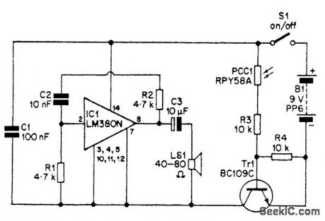
The circuit is activated if Tr1 is switched on by a suitable base current and voltage. The voltage and current available aJt the base of Tr1 are dependent on two main factors: the resistance provided by R4 and the setting of control VR1. If VR1 is set at maximum value, photocell PCC1 needs to have a resistance of about 10,000 Ω to bias Tr1 into conduction and activate the audio alarm circuit, of which IC1 is a primary part. Fixed resistor R4 has been used across the base-emitter terminals of the switching transistor so that the sensitivity of the circuit is preset. R4 can be raised somewhat in value if increased sensitivity is required. The audio-alarm generator uses an LM380N (IC1) in a simple au-dio-oscillator circuit, and drives high-impedance loudspeaker LS1 via coupling capacitor C3. Pro-vided the losses through this coupling are less than the voltage gain provided by the amplifier, this will give sufficient positive feedback to sustain oscillation. The values for R1, R2, and C2 shown in the circuit diagram give considerably more feedback than is needed to just sustain oscillations, and the circuit oscillates strongly, producing a square-wave output at a frequency in the region of 1 kHz (1000 Hz). (View)
View full Circuit Diagram | Comments | Reading(1363)
DUAL_BATTERU_CAPACITY_INDICATOR
Published:2009/7/14 2:19:00 Author:May
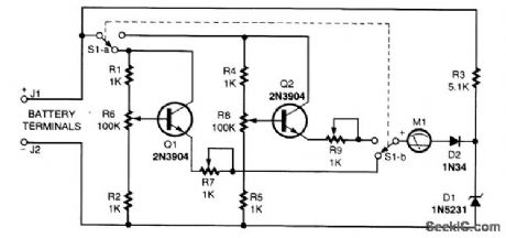
This indicator circuit uses two separate expanded meter scale circuits and can be calibrated for use with two different types of batteries. (View)
View full Circuit Diagram | Comments | Reading(1003)
STROBOSCOPE_FLASH_UNIT
Published:2009/7/14 1:42:00 Author:May
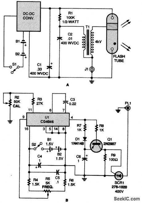
If you retrofit a flash unit (shown in A), it can accept signals from the circuit in B to operate as a precision stroboscope (View)
View full Circuit Diagram | Comments | Reading(1010)
STROBOSCOPE_TIMING_LIGHT
Published:2009/7/14 1:39:00 Author:May
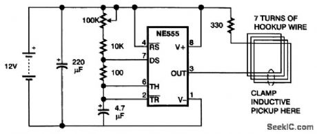
The NE555 produces brief pulses of current in the wire, which is wound into a loop to increase the amount of induction. To the timing light, these pulses look like the pulses that flow through a spark-plug wire. Bear in mind that the maximum frequency of a timing light is about 20 Hz. Above that frequency, timing lights tend to skip pulses. You might be able to speed up a timing light by reducing the value of the high-voltage capacitor across the flashtube; the light will then be dimmer, but the capacitor will charge tip more quickly for the next flash. (View)
View full Circuit Diagram | Comments | Reading(5650)
ELECTRONIC_TURBIDIMETER
Published:2009/7/15 22:40:00 Author:Jessie

A turbidimeter is a scientific instrument used to measure the cloudiness of solutions,such as water,if you measure the amount of scattered light,you can measure the turbidity. Paint the inside of the test-tube holder flat black Glue a cadmium sulfide photoresistor (R2)to a cardboard disk,and glue the assembly to the open end of the 90°tube Next,cement a biconvex lens (one that curves outward on both sides) to the bottom of the test-tube holder. Power up I1,a 12-V, 1-A automotive light bulb, and hold it at various distances below the biconvex lens. Find the distance at which a beam of light comes straight up the tube or converges slightly, but does not diverge. Mount the lamp and play it on the 100-μA meter; the resistors on the rotary switch set the sensitivity or attenuation. Power is supplied to the circuit by two 9-V batteries in a split supply; I run the lamp off a separate 12-V supply. If you want truly calibrated readings, you'll need to buy a turbidity standard solution, available in JTU (Jackson Turbidity Units) and NTU (Nephelos Turbidity Units), from a science-sup-ply company. In operation, zero the meter to a clean-water blank, note the reading from a known standard, note the reading from the unknown sample, and calculate the sample's turbidity, based on the needle's position. (View)
View full Circuit Diagram | Comments | Reading(2778)
PROGRAMMABLE_CONTROLLER_LIGHT_SENSOR_INTERFACE
Published:2009/7/15 22:32:00 Author:Jessie
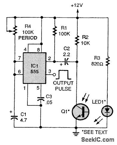
As long as an object remains between LED1 and Q1, no output occurs. But as soon as the object moves out from between the LED and the phototransistor, IC1 (a 555 timer) is triggered, producing a timed output pulse. This circuit can be used to indicate when a part has moved away from a location. (View)
View full Circuit Diagram | Comments | Reading(923)
LED_BATTERY_MONITOR_FOR_12_V_STSTEMS
Published:2009/7/14 1:18:00 Author:May
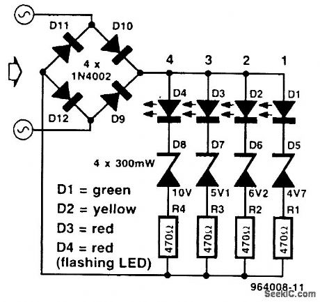
This monitor is handy in cars and is particularly suitable for radio amateurs who power their equipment from a car battery. Bridge rectifier D9-D12 ensures that the battery cannot be connected with incorrect polarity. The zener voltage of diodes D5-D8 increases in standard steps, so the battery voltage needs to be higher to cause successive LEDs to light. In other words, the higher the battery voltage, the more LEDs will light. The component values are chosen so that at a battery voltage of 9 V-battery poor-only D1 lights; when it is about 11 V-battery doubtful-D1 and D2 light; when it is 13 V-battery fine-D1, D2, and D3 light. Diode D4 is a flashing LED. The value of zener diode D8 is such that the LED begins to flash when the battery voltage approaches 15 V-that is, an overvoltage situation. (View)
View full Circuit Diagram | Comments | Reading(2339)
LIGHT_BLOCK_SENSOR
Published:2009/7/15 22:30:00 Author:Jessie
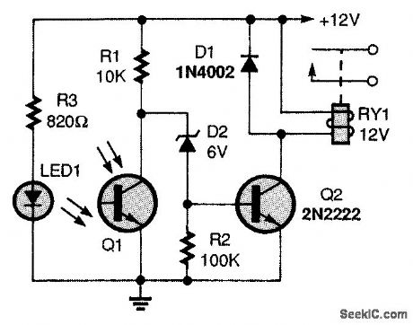
In this circuit, relay RY1 remains open until the light source is blocked. As long as the IR light source is uninterrupted, phototransistor Q1's collector voltage is near zero. The voltage at zener diode D2's cathode is too low for conduction, keeping transistor Q2 off and the RY1 open. (View)
View full Circuit Diagram | Comments | Reading(1770)
LAGHT_ACTIVATED_SWITCH
Published:2009/7/15 22:28:00 Author:Jessie
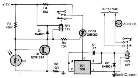
When even a little light hits light-dependent resistor R5, transistor Q1 is turned off because the base has less resistance to the ground than to the positive rail. In that situation, the base is at a negative potential. When the sun sets, R5 is no longer illuminated, giving the transistor's base a high resistance to ground-higher than 100,000Ω. With less resistance to positive potential, the base is biased, turning on Q1. Relay RY1 is then energized and pulls in, connecting the SCR1's anode to positive potential. The 555 timer, IC1, powers up, and its output goes high to approximately 10.67V, which is sufficient to energize RY2. Relay RY2 then pulls in, keeping the ac bulb on the whole night, and turning it off again at sunrise. (View)
View full Circuit Diagram | Comments | Reading(1106)
LOSS_OF_LIGHT_DETECTOR
Published:2009/7/15 22:26:00 Author:Jessie
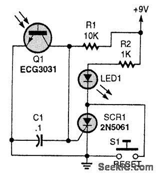
Light falling on Q1 causes Q1 to conduct. When the light fails, C1 charges toward +9V, triggering SCR1, lighting LED1. S1 resets the SCR. (View)
View full Circuit Diagram | Comments | Reading(904)
MAGIC_WAND
Published:2009/7/15 22:22:00 Author:Jessie
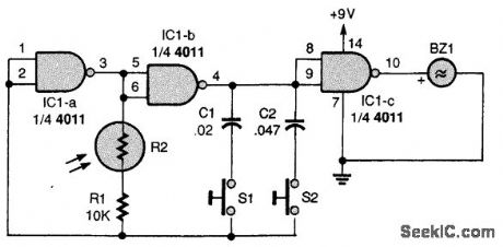


This device is easy to use: Just aim the wand at a light source and listen to the tone. Two gates, IC1-a and IC1-b, of a quad two-input NAND gate are connected in an audio-oscillator circuit with R1, the photocell (R2), C1, and C2setting the tone of BZ1. When the photocell is aimed at alight source, its resistance drops and the oscillator's output tone increases in frequency. When either of tone switches (S1 or S2) is presse, the frequency range goes up. Pressing S2 shifts the oscillator into its highest-frequency range. Only one tone switch can be pressed at a time; if both switches are pressed simultaneously, the output stops. (View)
View full Circuit Diagram | Comments | Reading(1017)
MELODY_SOUND_TO_LIGHT_CIRCUIT
Published:2009/7/13 23:43:00 Author:May

A method of synchronizing a simple light show to a musical chip is given by the circuit diagrant shown. Here, a display of eight rows of four LEDs advances with each musical note. IC2 is a UM66 three-pin melody chip selected to generate the desired tune.When power is applied to IC2, the sequence plays once and then stops. Power must be reapplied to initiate a further rendition.IC1 is a 555 astable, which will constantly reenable the tune chip and repeat the melody. However, the maximum supply voltage of the UM66 range is 3.3 V; hence, a simple zener-diode supply based around two 500-mW 2V7 types (D1 and D2) is used. TR1 is a directly driven transistor amplifier and the melody is played through loudspeaker LS1. Each musical note, when present, also biases transistor TR2 on, which shunts capacitor C2 to ground. In the absence of a note, C2 charges, which causes op amp IC3 to change state at a point determined by preset potentiometer VR1. The output from IC3, pin 6, provides a clock pulse for IC4, a 4022 divide-by-8 counter. Its outputs drive a buffer transistor sequentially to illuminate a series of four LEDs. The light display then advances with each note. (View)
View full Circuit Diagram | Comments | Reading(1806)
CLIPPING_OPAMP
Published:2009/7/13 22:13:00 Author:May
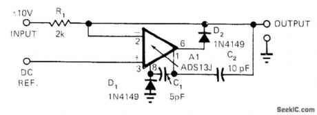
Simple circuit limits excursion of DC input voltage to level precisely equal to DC reference input voltage. When referenceis 0 V, circuit can be used as half-wave rectifier up to 100 kHz. Feedback overcomes breakover characteristics of D2, to provide sharp clipping at levels from mitlivolts to volts. At 10 kHz, with D1 omitted, range of levels is 70 mVRMS to 7 VRMS. With D1, circuit is useful at levels down to 0.3 VRMS at 100 kHz.-R. S. Burwen, Precision Clipper Operates from Millivolts to Volts, EDN Magazine, Dec. 1, 1972, p 57 and 59. (View)
View full Circuit Diagram | Comments | Reading(993)
| Pages:35/72 At 202122232425262728293031323334353637383940Under 20 |
Circuit Categories
power supply circuit
Amplifier Circuit
Basic Circuit
LED and Light Circuit
Sensor Circuit
Signal Processing
Electrical Equipment Circuit
Control Circuit
Remote Control Circuit
A/D-D/A Converter Circuit
Audio Circuit
Measuring and Test Circuit
Communication Circuit
Computer-Related Circuit
555 Circuit
Automotive Circuit
Repairing Circuit