
LED and Light Circuit
Index 34
LOW_CURRENT_FLASHER
Published:2009/7/14 4:36:00 Author:May

Q1 is operated in inverted configuration for lower leakage current. Typical on time is 0.2 sec and off lime 0.8 sec. Q1 is 2N132 and Q2 is 2N1374. Can be used as construction barricade flasher, flashing single lamp at 1 cps for up to 60 days on single battery. Use of solar-cell switch for S1, to turn off lasher automatically in daytime, will roughly double battery life in unattended locations.-Texas Instruments Inc., Transistor Circuit Design, McGraw-Hill, N.Y., 1963, p 425. (View)
View full Circuit Diagram | Comments | Reading(1614)
VARIABLE_DUTY_CYCLE
Published:2009/7/14 4:36:00 Author:May
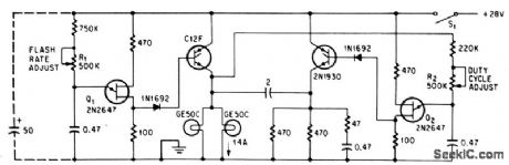
Unijunction transistor Q2 controls on time of lamp load.-D.V.Jones, Quick-On-The-Trigger Design, Electronics, 38:12, p 105-110. (View)
View full Circuit Diagram | Comments | Reading(0)
FLASHTUBE_TRIGGER
Published:2009/7/14 4:25:00 Author:May
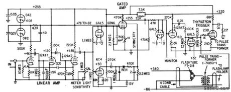
Uses 2D21 thyratron switch to discharge capacitor across primary of high-vohage pulse transformer whenever thyratron is fired. Resulting pulse is applied to trigger electrode of flashtube. Fires reliably up to 60 times per second. Used to illuminate number on aluminum indexing wheel on spinning shaft of magnetic gage used to locate exact position of ferromagnetic barrier encapsulated in shaped-charge container.-P. Seward, Magnetic Gage Locates Encased Metal Parts, Electronics, 31:33, p 65-67. (View)
View full Circuit Diagram | Comments | Reading(1931)
UNDERWATER_CAMERA_FLASH
Published:2009/7/14 4:31:00 Author:May
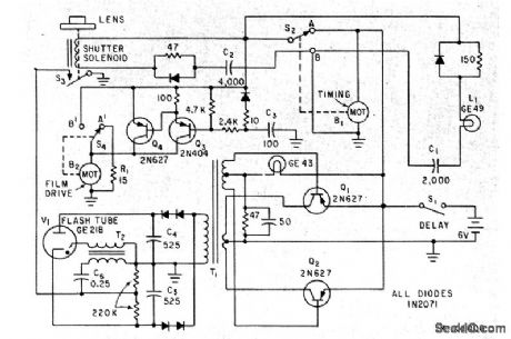
Film drive motor and camera shutter are interlocked with electronic flash so camera can be operated blindly at depths up to 6 miles, with lash occurring only when shutter is open.. Adjustable mechanical time-delay switch S1 delays start of operating cycle until camera is at operating depth. Timing switch S2 then takes picture every 12 sec for two hours.-H. E. Edgerton and S. O. Raymond, Instrumentation for Exploring the Oceans, Electronics, 33:15, p 62-63. (View)
View full Circuit Diagram | Comments | Reading(1049)
TRANSISTORS_SWITCH_10_AMP_PULSES_FOR_LIGHT_EMITTING
Published:2009/7/14 4:28:00 Author:May
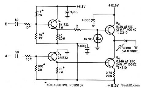
Input A must precede and follow B by 1 microsec to give 1-microsec width for 10-width for 10-amp pulses driving light-emitting diodes at repetition rates up to 100 kc.-E. L. Bonin, Drivers for Optical Diodes, Electronics, 37:22, p 77-82. (View)
View full Circuit Diagram | Comments | Reading(798)
ROTATING_BEACON
Published:2009/7/14 4:18:00 Author:May
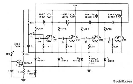
Four lamps flash one at a time, beginning with lamp 1, when power is applied, to simulate rotating light for emergency vehicles. R1 controls speed.-D. V. Jones, Quick-On-The-Trigger Design, Electronics, 38:12, p 105-110. (View)
View full Circuit Diagram | Comments | Reading(1489)
Q_MULTIPLIER_FOR_F_M_MONITOR
Published:2009/7/15 4:43:00 Author:Jessie
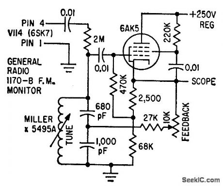
Checks calibration of f-m and television transmitter percentage-of-modulation monitors by using Q multiplier with monitor to make Bessel function measurements.-D. S. Henry, Cali-brating Broadcost Modulation Meters, Electronics, 33;16, p 67. (View)
View full Circuit Diagram | Comments | Reading(1691)
CONSTANT-CURRENT_LED
Published:2009/7/14 4:01:00 Author:May
National NSL4944 LED having built-in current control features can be used in simple circuit shown to provide current limiting and short-circuit protection for 15-V supply Even、With output shorted, LED draws only a little more than rated current.- Linear Applications、vol. 2, National Semiconductor, Santa Clara, CA, 1976, AN-153,p3 (View)
View full Circuit Diagram | Comments | Reading(1146)
DIFFERENTIAL_LINE_RECEIVER
Published:2009/7/15 4:36:00 Author:Jessie
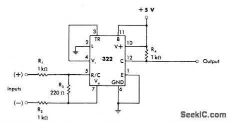
Responds to balanced-input drive signals fed to both comparator inputs of 322. Output is undisturbed even with up to 1 V of common-mode noise on input lines. TTL-compatible output is in phase with positive input. Overall delay is about 1 μs.-W. G. Jung, IC Timer Cookbook, Howard W. Sams, Indianapolis, IN, 1977, p 153-155. (View)
View full Circuit Diagram | Comments | Reading(1093)
PULSE_AMPLITUDE_MODULATOR
Published:2009/7/15 4:36:00 Author:Jessie
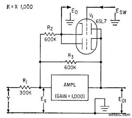
Used in multiplier that acts with one of operational amplifiers of analog computer. Double-triode V1 here provides pulse-amplitude modulation, for use with separate pulse-width modulator to form desired product of two input variables.-A. J. Ferraro, Multiplier for Analog Computers, Electronics, 33:45, p 73-74. (View)
View full Circuit Diagram | Comments | Reading(2006)
CRO_AS_TV_MONITOR
Published:2009/7/15 4:31:00 Author:Jessie
Permits monitoring transmitted amateur televison I signals with oscilloscope for such applications as checking sync levels and sync-pulse shape Outgoing signal can be monitored while adjusting modulator -Circuits、73 Magazine, March 1977 p 152. (View)
View full Circuit Diagram | Comments | Reading(986)
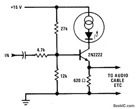
LINE_DRIVER_FOR_LED
Published:2009/7/15 4:24:00 Author:Jessie
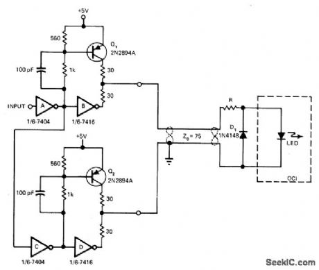
Single-ended input is converted to balanced differential drive for feeding 75-ohm transmission line terminated by LED serving as input for optically coupled line receiver. Logic 1 input is inverted to logic 0 by inverter A, turning on a, and turning off out-put of gate B. At same time, output of inverter A is logic 1, which inhibits turn-on of Q1 and makes output of inverter D go low. Thus, logic 1 input means that current is sourced into line and LED by Q1 then sunk by output of D. Similarly, logic 0 input results in current being sourced into line by Q2 and sunk by inverter B, making diode D1 conduct and turn off LED of OCI receiver. -K. Erickson, Line Driver Is Compatible with OCI Line Receiver, EDN Magazine, Oct. 5, 1976, p 106. (View)
View full Circuit Diagram | Comments | Reading(949)
TELEPHONE_RING_FLASHER
Published:2009/7/14 3:41:00 Author:May
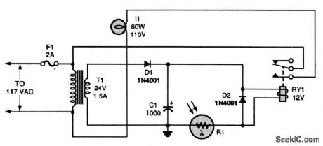
When the phone rings, the flasher turns on and off, causing photocell R1 to conduct. Relay RY1 is then energized, which completes the circuit between the light and the ac line. Thus, the light flashes in step with the rings. (View)
View full Circuit Diagram | Comments | Reading(1298)
SIMPLE_PHONE_IN_USE_INDICATOR
Published:2009/7/14 3:32:00 Author:May
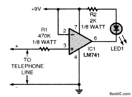
The LM741 op amp is used as a voltage comparator, comparing the telephone-line voltage to the battery voltage. The telephone line drops below 9 V when it is in use. That drop turns the op amp on, which lights the LED. Resistor R1 prevents the circuit from loading the telephone line excessively. In my location, the in-use circuit drops the line voltage approximately 5 V. That leaves quite a bit of re-serve because a telephone line operates at approximately 40 to 48 V. Resistor R2 limits the current to the LED. A 1000-Ω resistor will brighten the LED; however, the total circuit current draw will in-crease. The circuit (as shown) consumes 1.15 mA in standby and 3.80 mA when indicating that the line is in use. (View)
View full Circuit Diagram | Comments | Reading(2199)
ELEPHONE_BELL_INDICATOR_CIRCUIT
Published:2009/7/14 3:25:00 Author:May
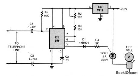
This circuit uses a 555 timer to gate an SCR. The SCR passes 12 V to an alarm bell. The bell should be of the mechanical interrupter type so that it will reset and ring only when ring signals are on the telephone line. (View)
View full Circuit Diagram | Comments | Reading(3010)
PULSE_WIDTH_MONITOR
Published:2009/7/15 5:45:00 Author:Jessie
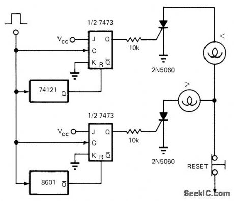
Circuit turns on upper pilot lamp when pulse width is less than predetermined minimum value, because upper 7473 JK flip-flop is clocked when pulse falls to ground before 74121 mono recovers, triggering upper SCR on. Similarly, 8601 mono is set to coincide with specified maximum pulse width; if pulse falls to ground after this mono recovers, its JK flip-flop is clocked and lower (greater than) lamp is turned on. Fault indication is held until reset button is pushed.-J. Kish, Jr., Three ICs Monitor Pulse Width, EDN Magazine, March 20, 1973, p 86. (View)
View full Circuit Diagram | Comments | Reading(1985)
40_dB_LOGAMP
Published:2009/7/14 3:02:00 Author:May

Uses Optical Electronics 2457 logarithmic module containing two pairs of bipolar log elements and three opamps. Connection shown produces pure tog10 function on positive inputs. Zero point is set by R2 or by reference e. Reference must be positive for pos-tive logs and negative for negative logs. Trim 110K resistors for exactly 10-V output,- Two-Decade Precision Logarithmic Amplifior, Optical Electronics, Tucson, AZ, Applicatlon Tip 10212. (View)
View full Circuit Diagram | Comments | Reading(698)
BINARY_CHANNEL_FOR_EL_DISPLAY
Published:2009/7/15 21:13:00 Author:Jessie
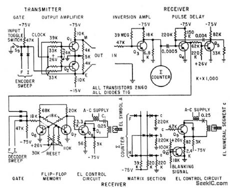
Information is transmitted to decoding unit and display board in series of pulse bursts. each containing entire information to be displayed, for rapid error correction if information is garbled during transmission. System can use pair of wires for transmission, having sufficient bandwidth to pass pulse burst. Information is introduced by opening S9 in transmitter-R. C. Lyman and C. I. Jones, Electroluminescent Panels for Automatic Displays, Electronics, 32:28, p 44-47. (View)
View full Circuit Diagram | Comments | Reading(971)
SONAR_TIMER_AND_CRO
Published:2009/7/15 21:08:00 Author:Jessie
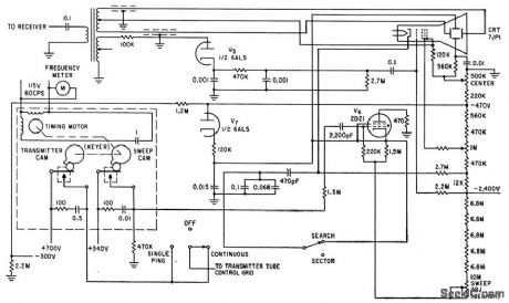
Timing functions, induding display, are derived from cam op erated switches driven by synchronous motor. Thyrcmon V6 discharges sweep capacitor. Leading edge of received echo is cdigned by delay control with crt reference Iine, and delay time in millisec is read di-rectly from dial.-L. H. Dulberger, Sonar to Survey Arctic Ocean Shelf Transmits Through Ice and Water, Electronics, 34;31, p 44-45. (View)
View full Circuit Diagram | Comments | Reading(983)
1O_STATE_RING_COUNTER
Published:2009/7/15 21:06:00 Author:Jessie
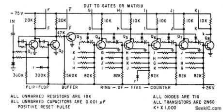
Flip-fiop drives ring-of-five stage that in tum drives diode malrix which trcnslales each slored deci-mal number to electroluminescent display segment code.-R. C. Lyman and C. I. Jones, Eleclroluminescenf Panels for Aulomatic Displays, Electronics, 32:28, p 44-47. (View)
View full Circuit Diagram | Comments | Reading(922)
| Pages:34/72 At 202122232425262728293031323334353637383940Under 20 |
Circuit Categories
power supply circuit
Amplifier Circuit
Basic Circuit
LED and Light Circuit
Sensor Circuit
Signal Processing
Electrical Equipment Circuit
Control Circuit
Remote Control Circuit
A/D-D/A Converter Circuit
Audio Circuit
Measuring and Test Circuit
Communication Circuit
Computer-Related Circuit
555 Circuit
Automotive Circuit
Repairing Circuit