
Audio Circuit
Index 11
AN5265 audio circuit diagram
Published:2011/10/18 1:40:00 Author:Rebekka | Keyword: audio circuit
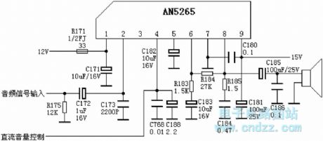
AN5265 pin function and the reference voltage: Pin 1: 12V - Front-level power Pin 2: 5V - audio signal input Pin 3: 0V - mute control terminal (high, quiet) Pin 4: 0.1V - Volume control voltage inputPin 5: 7V - filter-side Pin 6: 7.4V-- negative feedback input Pin 7: 0V -groundPin 8: 7.5V-output end of power amplifierPin 9: 15V - power amplifier class (View)
View full Circuit Diagram | Comments | Reading(14478)
LA4287 audio circuit diagram
Published:2011/10/17 22:05:00 Author:Rebekka | Keyword: audio circuit
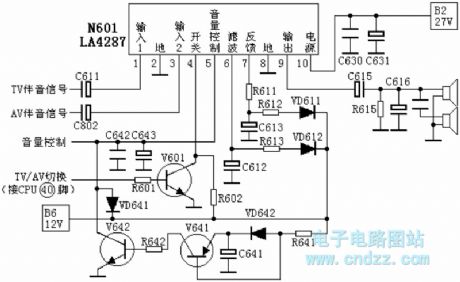
TV sound signal isinput from the N601's pin 1, andAV audio signal is input from the N601's pin 3. The TV/AV switching signal output by CPU(40)feet bypassing the base ofR601 to V601. Thepin 4 isinverted by V601 chosen by the internal and output signal through N601 pin 9. Then itmakes the speaker sound. The shutdown audio squelch circuit is composed of V641 and V642. In the normal boot, 12V voltage passes R641, then it isadded to the base of V641 and the emitter VD642. Due to the existence of VD642, V641 base voltage is 0.7V, which ishigher than high-emitter voltage. V641 and V642 are stopped. The loop has no influence on volume control.
1 pin: 6.3V-- signal input 12 pin: 0V - to 3 pin: 6.3V-- signal input 24 pin: 2.1V-- signal switch 5 pin: 0.67V-- volume control voltage input6 pin: 9.8V-- Filter 7 pin: 9.8V-- Feedback 8 pin: 0V - to 9 pin: 9.9V-- output pin 10 pin: 21V - Power Supply (View)
View full Circuit Diagram | Comments | Reading(11570)
TA8211AH audio circuit diagram
Published:2011/10/17 21:29:00 Author:Rebekka | Keyword: audio circuit
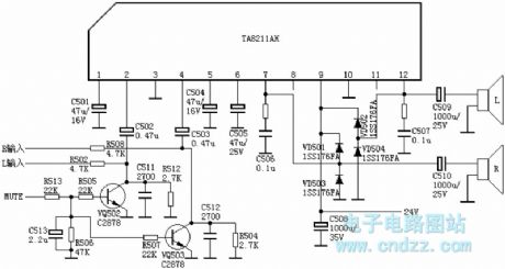
Changhong C2588 TVpin 1: 2.1V-- left channel negative-feedback external capacitor pin 2: 2.2V-- left channel signal input pin 3: 0V - ground pin 4: 2.2V-- right channel signal input pin 5: 2.1V-- right channel negative feedback external capacitor pin 6: 8.2V-- power supply filter pin 7: 12V - right channel signal outputpin 8: 2.2V-- empty pin 9: 24V - power supply pin 10: 0V - ground (PA) pin 11: 2.2V-- empty pin 12: 12V - left channel signal output (View)
View full Circuit Diagram | Comments | Reading(3734)
Video multiplexor circuit diagram
Published:2011/9/13 2:53:00 Author:Rebekka | Keyword: Video multiplexor
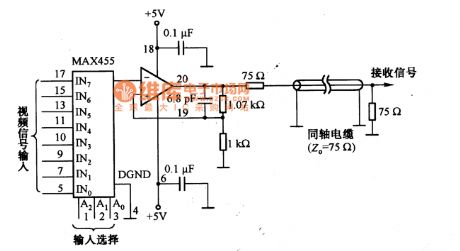
Figure shows a video signal multiplexer, which uses the video amplifier MAX455 with a switch. MAX455 is an integrated chip which includes high isolation analog switch and video frequency amplifier. The frequency of MAX455 is 4MHz, the disconnected isolation of the switch off can achieve 55dB. (View)
View full Circuit Diagram | Comments | Reading(3961)
LM4911 OCL output earphone amplifier circuit diagram
Published:2011/8/22 22:16:00 Author:Rebekka | Keyword: OCL output , earphone amplifier
LM4911 is a stereo headphone amplifier with 3.3V power supply. Every channel outputs 40mW that continuous average power drives 16Ω load, or every channel outputs 25mWand continuous average power drives 32Ω load. LM4911 can use single-ended capacitive coupling output or OCL output structure. It has a low-power shutdown mode and power squelch mode. When the release changes in the output voltage is less than 1mV, the breakover turns fast. LM4911 also contains an internal thermal shutdown protection agency, the pin arrangement is shown as the chart.
(View)
View full Circuit Diagram | Comments | Reading(1322)
Wiring Circuit of the Speaker
Published:2011/9/12 23:55:00 Author:Zoey | Keyword: Wiring Circuit, Speaker
Picture 20 shows the connection cable of the speaker, the connection cable uses a resistance that has small consumption and good response. Generally, speakers’ resistance is about several Ωto dozens Ω,and it is largely affected by power pinchoff produced by cable equivalent resistance. Therefore, the cable chose should have a low current resistance. In addition, frequency response of transportation signal is mainly determined by texture and material of the cable, the cable should be easily controlled by frequency response.
How to choose transistors and FET
Transistor circuits can be mainly divided into amplified circuit, switched circuit and oscillation circuit. Transistors available for these circuits are high frequency transistors, high amplifier factor transistors, high power transistors and general transistors.
General transistors: Japanese 2SA1048(UCEO=50V,Ic=150MA,Pc=200mW,hFE=70~400,T=80MHZ) and 2SC245(UCEO=5OV,Ic=15OMA,PC=2OOmW,hFE=70~700,T=80MHZ);Genral high frequency transitors: Japanese 2SC2668(UcEO=30V,Ic=2OmA,Pc=1OOmW,hFE=40~200,T=550MHZ) and 2SC3136(UCEO=20V,Ic=50mA,PC=250mW,hfe=40~300,T=1400KHZ);Genral crystal transitors: Japanese 2SA1516(UcEO=180V,IC=12A,Pc=130W,hFE=55~180,T=25MHZ) and 2SC3907(UCEO=180V,Ic=12A,PC=130W,hFE=55~180,T=30MHZ);
Genral dual transitors:Japanese 2SA1349(UCEO=80V,Ic=100MA,Pc=200mWx2,hFE=200~700)and 2SC3381(VCEO=80V,IC=1OOMA,Pc=200x2mW,hFE=200~700)。Chinese low power low frequency transistors:3AX、3BX、3CX、3DX series. General FET:2SJ105(UGDS=5OV,IDSS=1.2~1.4mA,PD=2OOmW,Ciss=18pF) and 2SK330(UGDS=5OV,IDSS=1.2~1.4mA,PD=2OOmW,CISS=9pF);High frequency FET:2SK241(UGDS=2OV,IDSS=1.5~14mA,PD=2OOmW,Ciss=3pF);Power FET: 2SJ200(UGDS=180V,IDSS=1OA,PD=12OW,CiSS=1300pF) and 2SK1529(UGDS=180V,IDSS=1OA,PD=12OW,Cis=700pF);Dual tubes:2SJ109(UGDS=30V,IDSS=2.6~2OmA,PD=2OOmW,Ciss=95pF) and 2SK389(UGDS=5OV,IDSS=2.6~2OmA,PD=2OOmW,Ciss=25pF)。 (View)
View full Circuit Diagram | Comments | Reading(1646)
Radio Advertising Voice Circuit
Published:2011/9/12 23:45:00 Author:Felicity | Keyword: Radio Advertising, Voice, Circuit
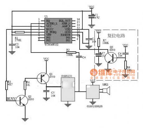
Work of the circuit
BUSY signal is the Uniquefeatureof the voice chip. We can use it to control the power circuit of the radio.
(View)
View full Circuit Diagram | Comments | Reading(1481)
Voice recording control circuit
Published:2011/9/9 2:09:00 Author:John | Keyword: Voice recording control

W5120 is a multifunctional IC produced by Taiwan's Winbond Company. It contains a microphone top-level, automatic gain control, smoothing filter, A / D, D / A, speaker amplifier, calibration logic control point and external Serial SRAM (SSRAM) port. W5120 provides 63 voice recording sections. It can cascade multiple SSRAM, whose high level triggers the REC to work. And it provides long records without needs to reset (RESET). Quiet time compression is provided to save storage space. Besides, two overflow prevention functions are equipped (Serial SRAM is easy to overflow and so is the section index.)
(View)
View full Circuit Diagram | Comments | Reading(1783)
Circuit Diagram of 2576+358+Voltage Regulator Tube Pattern
Published:2011/9/9 9:08:00 Author:Zoey | Keyword: Voltage Regulator Tube
Advantages:
(1) As 2576 has an interior overcurrent and overtemperature-proof device, it can input constant voltage, constant current CC and overvoltage proof OVP together with 358, so as to achieve a reliable, safe and perfect charge solution of lithium cells.
(2) EMI design of automobile charger is relatively easy for 2576 is a fixed 52-k PWM convertor.
(3)Both 2576 and lm358 are made in high pressure and dual polar, so they are very firm.
(4)This solution is usually used in automobile charger of 0.8A~1.5A.
Disadvantages:
(1) Its system is complex and costly.
(2) CC and OVP control the 2576 EN by 358’s input, therefore, the charge current has a relatively large wave, and corresponding speed of CC and OVP is not prompt enough.
(View)
View full Circuit Diagram | Comments | Reading(1275)
The 30W single terminal audio power amplifier circuit of type A
Published:2011/8/23 22:13:00 Author:Borg | Keyword: single terminal, audio power amplifier
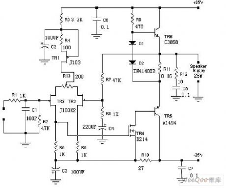
The 30W single terminal audio power amplifier circuit of type A is shown as above.
(View)
View full Circuit Diagram | Comments | Reading(3471)
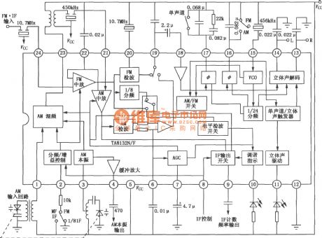
TA8132N,8132F digital tuned AM,FM stereo radio circuit
Published:2011/8/25 20:20:00 Author:chopper | Keyword: digital tuned, AM,FM, stereo, radio circuit
View full Circuit Diagram | Comments | Reading(3326)
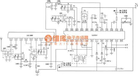
LA1810,1811 AM,FM stereo radio circuit
Published:2011/8/25 20:19:00 Author:chopper | Keyword: AM/FM, stereo, radio circuit
View full Circuit Diagram | Comments | Reading(6573)
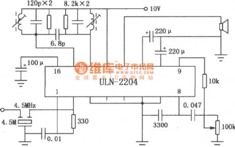
ULN2204A FM,AM radio circuit
Published:2011/8/25 20:19:00 Author:chopper | Keyword: FM,AM, radio circuit
View full Circuit Diagram | Comments | Reading(4008)
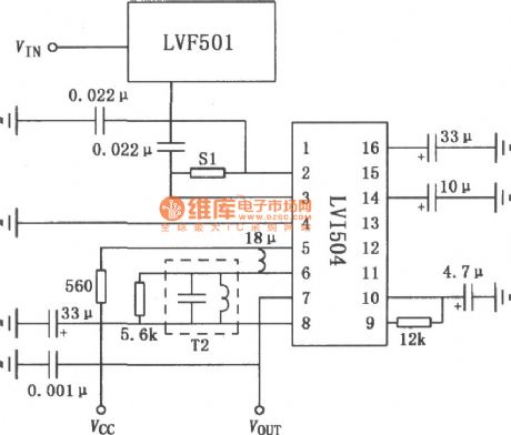
LVF501 FM radio tuner circuit
Published:2011/7/25 2:17:00 Author:chopper | Keyword: FM radio, tuner circuit
View full Circuit Diagram | Comments | Reading(1473)
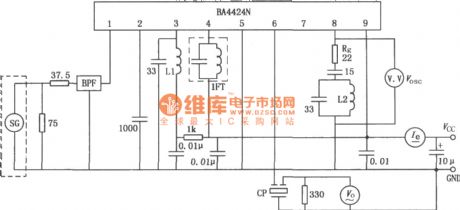
BA4424N FM radio tuner circuit
Published:2011/7/25 2:18:00 Author:chopper | Keyword: FM radio, tuner circuit
View full Circuit Diagram | Comments | Reading(2103)
AN7220,7221 FM,AM intermediate frequency amplifier circuit
Published:2011/8/25 20:21:00 Author:chopper | Keyword: FM,AM, intermediate frequency, amplifier circuit

View full Circuit Diagram | Comments | Reading(3350)
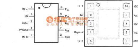
PT-8820 "idiot" type record-replay audio integrated circuit
Published:2011/7/23 2:56:00 Author:chopper | Keyword: "idiot" type, record-replay, audio, integrated circuit
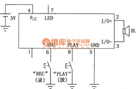
PT-8820 is the audio product of PT series.The product uses an advanced level to directly simulate the flash memory technology, and it can provide nonvolatile sound or data storage without A/D, D/A converter, which can provide high-quality audio playback, and can catch up with digital recording effect. PT-8820 does not need back-up battery, and the recording information will not lost when the power is off. As a result ofthe unique bi-directional analog I/O speech switching technology, PT-8820 can use the speaker as a microphone for recording,which is easy to form the simplest sound recording circuit. (View)
View full Circuit Diagram | Comments | Reading(1683)
HT8656 record and playback integrated circuit
Published:2011/7/23 3:03:00 Author:chopper | Keyword: record, playback, integrated circuit
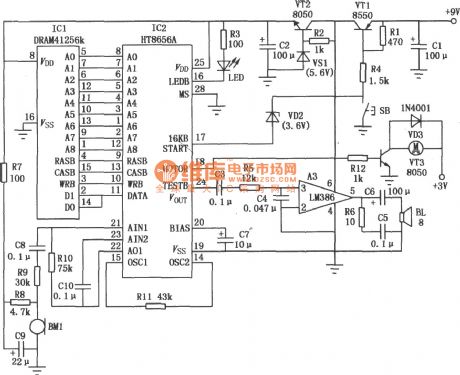
In the HT8656 record and play back voice IC there is a sound auto-detection circuit.When the circuit is in a wait state, the microphone receives a sound signal,and the circuit will automatically enter the recording state;when the sound stops (or be silent) about 1s, the circuit will automatically turn the recording state into playback state, and it will automatically return to the wait state after the end of the playback.It is used for voice-operated words learning toys, arts and crafts. Typical application circuit is shown as picture. (View)
View full Circuit Diagram | Comments | Reading(1859)
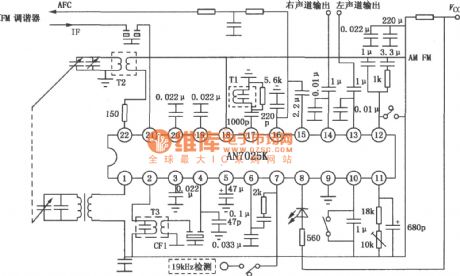
AN7025K/7025S AM/FM stereo radio circuit
Published:2011/7/23 2:39:00 Author:chopper | Keyword: AM/FM, stereo, radio circuit
View full Circuit Diagram | Comments | Reading(4340)
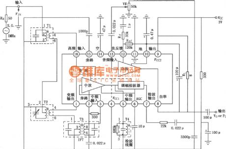
TA7641BP low-consumption AM radio circuit
Published:2011/7/23 2:35:00 Author:chopper | Keyword: low-consumption, AM, radio circuit
View full Circuit Diagram | Comments | Reading(2708)
| Pages:11/54 1234567891011121314151617181920Under 20 |
Circuit Categories
power supply circuit
Amplifier Circuit
Basic Circuit
LED and Light Circuit
Sensor Circuit
Signal Processing
Electrical Equipment Circuit
Control Circuit
Remote Control Circuit
A/D-D/A Converter Circuit
Audio Circuit
Measuring and Test Circuit
Communication Circuit
Computer-Related Circuit
555 Circuit
Automotive Circuit
Repairing Circuit