
Audio Circuit
Index 14
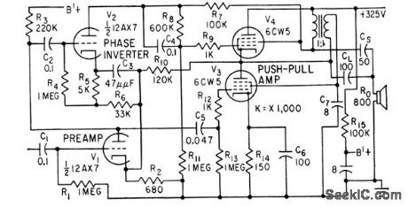
EL156 Tube Amp Circuit
Published:2011/8/6 8:52:00 Author:Felicity | Keyword: Tube Amp Circuit

View full Circuit Diagram | Comments | Reading(5567)
eight continuous sound space gun circuit(CD4069,KD9562)
Published:2011/7/22 2:56:00 Author:chopper | Keyword: eight, continuous sound, space gun
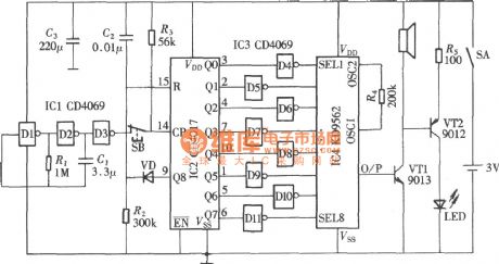
KD9562 is a toy phonation circuit which can send out 8 analog sound, and it has 8 trigger ends. Put it in a toy gun, it will send outa analog sound each time users press it.If you use a trigger pulse distributor to trigger its eight trigger ends take turns, it will form a eight sound space gun circuit which can send out continuous sound, the circuit is shown as picture.Circuit consists of eight analog phonation circuit KD9562, trigger pulse generator, pulse distributor,and the trigger pulse inverter. (View)
View full Circuit Diagram | Comments | Reading(2200)
unique sound generating circuit with CD4040,CD4069
Published:2011/7/22 2:43:00 Author:chopper | Keyword: sound, generating circuit
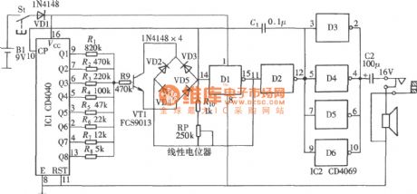
The sound generating circuit can produce the sound which is similar to bird singing, car sirens and spacecraft sound,and it is a good toy for children.The circuit is shown in the picture.Core part is formed by a controlled oscillator composed of the gate circuit,which can change the oscillator frequency by adjusting the control voltage of the controlled oscillator, resulting in sending out a variety of analog sound. (View)
View full Circuit Diagram | Comments | Reading(4418)
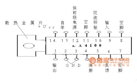
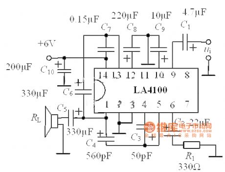
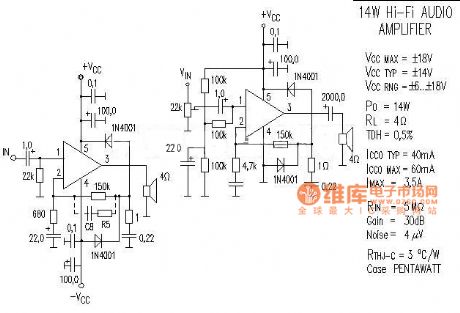
LA4100 Series Integrated Amplifier and Application Circuit
Published:2011/7/17 21:12:00 Author:Felicity | Keyword: LA4100 Series, Integrated, Amplifier, Application, Circuit
View full Circuit Diagram | Comments | Reading(4546)
High-voltage Rectifier Circuit Of Side Thermal Rectifier Tube
Published:2011/7/17 20:56:00 Author:Felicity | Keyword: Side Thermal, Rectifier Tube, High-voltage Rectifier, Circuit
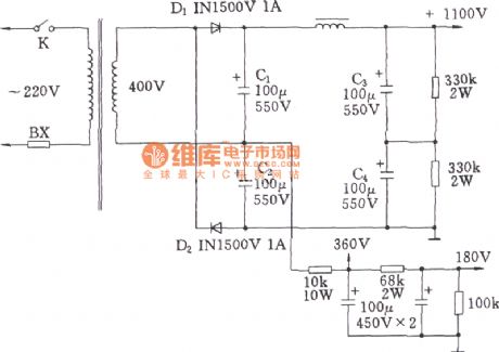
View full Circuit Diagram | Comments | Reading(1364)
Power Amplifier Circuit
Published:2011/7/17 21:01:00 Author:Felicity | Keyword: Power Amplifier, Circuit
View full Circuit Diagram | Comments | Reading(1388)
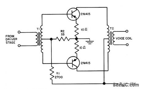
10_W_SINGLE_ENDED_PUSH_PULL_OUTPUT
Published:2009/7/14 22:18:00 Author:Jessie
Feeds voice coil directly, making output transformer unnecessary. First preamplifying stage has positive feedback to point ofoscillation, while amplifier and output stages have negative feedback. Circuit haslow distortion, fiat response, and only a few degrees of phase shift over audio range.-J. Rodrigues De Miranda, Push. Pull Amplifiers Drive Speaker Directly,Electronics, 31:29, p 76-79. (View)
View full Circuit Diagram | Comments | Reading(1217)
Q_MULTIPLIER
Published:2009/7/14 22:15:00 Author:Jessie
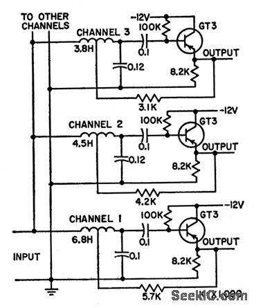
Circuit shows three channels of multi-channel selective a-f ampliler(190, 216.5, and 235 cps) using various coil-capacitor combinations with transistorQ multiplier to provide staggered resonant frequencies. Used in frequency- selectiye calling systems.-G. B. Miller, Transistor Q Multiplier for Audio Frequencies,Electronics, 31:19, p 79-81. (View)
View full Circuit Diagram | Comments | Reading(0)
BASIC_CLASS_B_PUSH_PULL_OUTPUT
Published:2009/7/14 22:30:00 Author:Jessie
Design procedures are given. Resistor in emitter leads prevent thermal runaway when ambient temperature is below 55℃ .- TransistorManual , Seventh Edition, General Electric Co.,1964,p 242. (View)
View full Circuit Diagram | Comments | Reading(1281)
PREAMPLIFIER_FOR_DYNAMIC_PICKUP
Published:2009/7/14 22:43:00 Author:Jessie

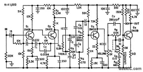
Accepts signal from variable-reluctance cartridge.Includes RIAA frequency-correcting network, variable bass and treble compensation,volume control, and loudness control that attenuates midfrequencies as loudnesslevel is decreased, to emphasize lows and highs during soft musical passages.-R.Minton,Designing High-Quality A-F Transistor Amplifiers, Electronics, 32:24, p 60-61. (View)
View full Circuit Diagram | Comments | Reading(2417)
ZONED_PUBLIC_ADDRESS_IN_PLANE
Published:2009/7/14 22:38:00 Author:Jessie


Uses single preamplifier and up to five Power amplifiers and speakers to distribute sound uniformly throughout seating area of plane. Air-ground output switch acts on all amplifiers simultaneously to compensatefor different noise levels on ground than in air,-Transistorized P-A System Adjuststo Aircraft Noise, Electronics, 31:7, p 106-107. (View)
View full Circuit Diagram | Comments | Reading(1073)
LOW_COST_LINE_OPERATED_PHONO
Published:2009/7/14 23:16:00 Author:Jessie
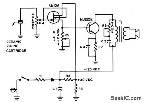
Provides 1 w output with only two transistors. Highinput impedance (above 10,000 meg) of fet permits direct drive by high-outputcartridge, while MJ2252 npn silkon transistor operotes directly from 120 v d-c output of simple power supply using Motorokt 1N4004 sur melic silicon rectiner.Volues are:C1-100 mfd; C2-0.1 mfd; C3-100 mfd, 3v; R1-330; R2-10K; R3-3K; R4-1 meg;R5-5K; R6-l00K; R7-33.-D. L. Wollesen, A Line Operctted Solid State PhonogmphAmplifier, Motorokt Applkation Note AN-183, Feb. 1966. (View)
View full Circuit Diagram | Comments | Reading(1160)
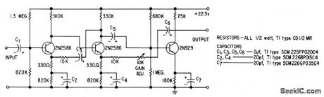
THREE_STAGE_CASCADED_COMMON_EMITTER
Published:2009/7/14 23:06:00 Author:Jessie
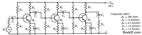
Gives current gain of 90 db at 1 kc,outputvoltage swing is 2 v peak-to-peak. All transistors are 2N1565. Values of C1 and C2depend upon frequency response desired; typical values are to and 100 mfd respectively.-Texas Instruments Inc., Transistor Circuit Design, McGraw-Hill,N.Y.,1963, p 205. (View)
View full Circuit Diagram | Comments | Reading(1156)
TWO_FET_CASCODE
Published:2009/7/14 23:04:00 Author:Jessie
Gives high audio voltage gain (40 db), high impedance, low-noise operation, and good temperature stability with low supply voltage. Q3 serves as loadresistance.-B. Smith, Low-Noise FETs Sound Good To Circuit Designers, Electronics,37:31, p 58-62. (View)
View full Circuit Diagram | Comments | Reading(1295)
VELOCITY_RESPONSE_PHONO_PREAMP
Published:2009/7/14 23:03:00 Author:Jessie

Designed for use with wide range of ceramic cartridge capacitances. Input impedance, which is 30K at 40 cps, decreases with increasing frequency to give velocity response from cartridge, so that preamp frequency response is like that required for a magnetic cartridge. Output is equalized within 1.6 db from 40 cps to 12 kc.- Transistor Manual, Seventh Edition, General Electric Co., 1964, p 258. (View)
View full Circuit Diagram | Comments | Reading(1833)
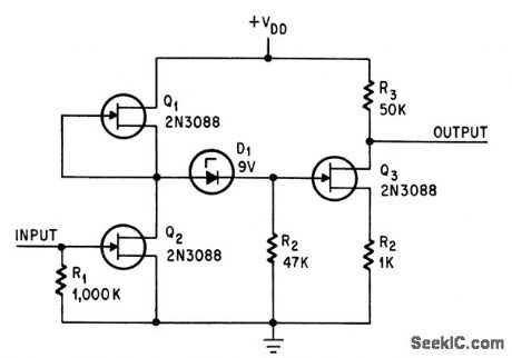
LOW_LEVEL_LOW_NOISE_HIGH_GAIN
Published:2009/7/14 23:00:00 Author:Jessie
Gives gains up to 1,000(60 db) for high-impedance,transducer applications, With typical noise figure of 1 db at emitter currents below 1 microamp and generator resistance above 1 meg. Such performance was previouslyavailable only with vacuum tubes and field-effect transistors. Ideal for spaceapplications.-Texas Instruments Inc., Solid .State Communications, McGraw-Hill,N.Y., 1966, p 291. (View)
View full Circuit Diagram | Comments | Reading(1290)
BOOTSTRAP_FET
Published:2009/7/15 2:00:00 Author:Jessie
Input impedance is high at low frequencies (180 meg at 10 cps), butdrops to 3 meg at 10 kc. High collector current contributes to high over-all noiselevel.-B. Smith, Low. Noise FETs Sound Good To Circuit Designers, Electronics, 37:31,p 58-62. (View)
View full Circuit Diagram | Comments | Reading(1444)
CAPACITOR_MIKE_PREAMP
Published:2009/7/15 1:57:00 Author:Jessie
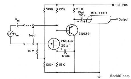
Fet provides required high input impedance. Can easily bemounted in microphone. Emitter-follower with output impedance of about 100 ohms willdrive 500 feet of microphone cable without appreciably affecting frequencyresponse.-L.J. Sevin, Jr., Field-Effect Transistors, McGraw-Hill, N.Y., 1965, p 75. (View)
View full Circuit Diagram | Comments | Reading(1221)
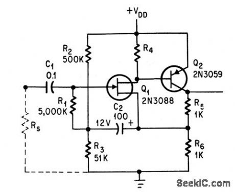
FET_PNP_DARLI_NGTON
Published:2009/7/15 1:55:00 Author:Jessie


P-channel fet is combined with pnp transistor in equivalent to Darlington connection, for use with high-input-impedance low-frequency transducers.Spot noise figure is 7 db at 10 cps and 3 db at 100 cps. Broadband noise figure from10 cps to 10 kc is 1.7 db with 200K generator resistance.-Texas Instruments Inc., Solid-State Communications, McGraw-Hill, N.Y., 1966, p 136. (View)
View full Circuit Diagram | Comments | Reading(1561)
LASER_RECEIVER_DETECTOR_AND_AUDIO_CIRCUIT_
Published:2009/7/14 11:49:00 Author:May
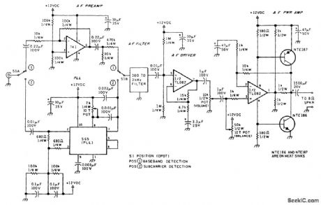
Video preamplifier output can be switched between an audio amplifier that establishes the correct level of the demodulated baseband audio when used for short distance test links and a phase-locked loop (PLL) that demodulates an FM subcarrier when used for longer distances. The PLL VCO is set to a 100-kHz subcarrier frequency. The error signal generated as the VCO tracks the FM signal produces the demodulated audio. Either of these outputs is sent to a 300- to 3000-Hz bandpass filter and on to an audio power amplifier capable of driving a low-impedance speaker or headphones. The dc power supply for these circuits is provided by a filtered 12 Vdc input. (View)
View full Circuit Diagram | Comments | Reading(2584)
| Pages:14/54 1234567891011121314151617181920Under 20 |
Circuit Categories
power supply circuit
Amplifier Circuit
Basic Circuit
LED and Light Circuit
Sensor Circuit
Signal Processing
Electrical Equipment Circuit
Control Circuit
Remote Control Circuit
A/D-D/A Converter Circuit
Audio Circuit
Measuring and Test Circuit
Communication Circuit
Computer-Related Circuit
555 Circuit
Automotive Circuit
Repairing Circuit