
Audio Circuit
Index 7
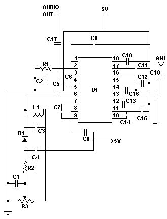
Single Chip FM Radio Circuit
Published:2012/12/12 0:31:00 Author:muriel | Keyword: Single Chip, FM , Radio Circuit
View full Circuit Diagram | Comments | Reading(2198)
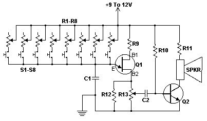
Transistor Organ
Published:2012/12/12 0:27:00 Author:muriel | Keyword: Transistor Organ
View full Circuit Diagram | Comments | Reading(1136)
3 Watt FM Transmitters
Published:2012/12/12 0:26:00 Author:muriel | Keyword: 3 Watt, FM Transmitters

View full Circuit Diagram | Comments | Reading(1093)
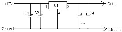
Portable CD Player Adapter For Car
Published:2012/12/12 0:19:00 Author:muriel | Keyword: Portable , CD Player Adapter, Car
View full Circuit Diagram | Comments | Reading(812)
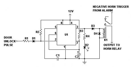
Car Alarm Arming Horn Beep Canceller
Published:2012/12/10 0:45:00 Author:muriel | Keyword: Car Alarm Arming, Horn Beep Canceller
View full Circuit Diagram | Comments | Reading(936)
Wireless Auto Tachometer
Published:2012/12/10 0:44:00 Author:muriel | Keyword: Wireless, Auto Tachometer
View full Circuit Diagram | Comments | Reading(1189)
The motor overheating language newspaper called circuit
Published:2012/11/21 20:48:00 Author:Ecco | Keyword: motor overheating, language newspaper called
It is composed of temperature sensor, electronic switch circuit and language utterance circuit. When motor fails to run in the hot season or at room temperature, the motor will often appear overheating. The circuit can issue the sound of beep , please note to remind duty personnel.
(View)
View full Circuit Diagram | Comments | Reading(1017)
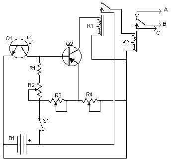
Sound of Light Circuit
Published:2012/11/21 21:09:00 Author:muriel | Keyword: Sound , Light Circuit

An experimental circuit that converts light to sound. The circuit uses a solar cell as the input transducer, blocks the DC produced by the cell, but amplifies the light received by the cell. Sunlight, moonlight, torchlight all produce sound which is amplified by this circuit. (View)
View full Circuit Diagram | Comments | Reading(2660)
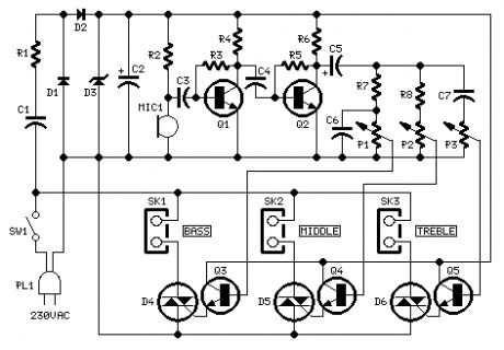
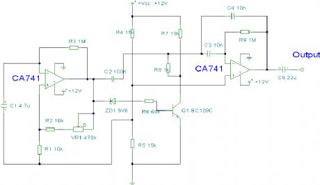
Guitar Reverb Effect Version 2
Published:2012/11/21 21:07:00 Author:muriel | Keyword: Guitar, Reverb, Effect Version
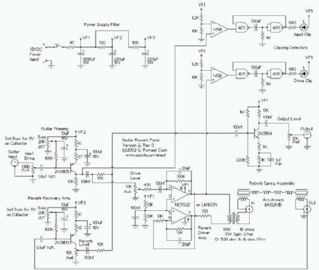
This is my second-generation guitar reverb circuit. The fidelity is much improved over the earlier design, it is suitable for use as a front-end to a guitar amplifier. This circuit features clipping indicators on the preamp and reverb recovery stages, allowing for the optimal gain settings. (View)
View full Circuit Diagram | Comments | Reading(1870)
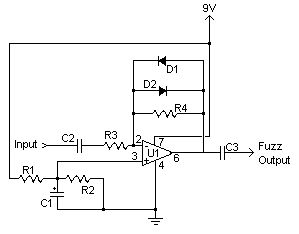
Guitar Fuzz Effect
Published:2012/11/21 21:01:00 Author:muriel | Keyword: Guitar Fuzz Effect
View full Circuit Diagram | Comments | Reading(1154)
Simple Color Organ
Published:2012/11/21 21:00:00 Author:muriel | Keyword: Simple Color Organ
View full Circuit Diagram | Comments | Reading(0)
Mini Metronome
Published:2012/11/21 21:00:00 Author:muriel | Keyword: Mini Metronome
View full Circuit Diagram | Comments | Reading(830)
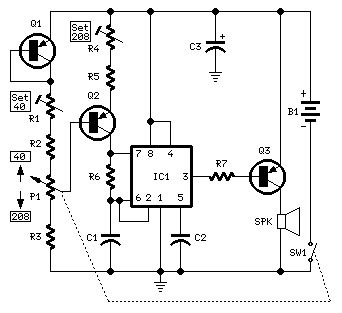
Electronic Siren
Published:2012/11/21 20:59:00 Author:muriel | Keyword: Electronic Siren
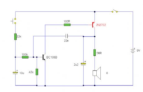
An electronic siren made from discrete components. A push button switch is used to create the sound, which rises in pitch when the switch is pressed, and falls in pitch when the switch is released. (View)
View full Circuit Diagram | Comments | Reading(0)
Sound Effects Generator 2
Published:2012/11/21 20:59:00 Author:muriel | Keyword: Sound , Effects Generator 2
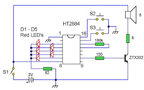
This circuit uses the Holtek HT2884 IC to produce 8 different sound effects. (View)
View full Circuit Diagram | Comments | Reading(884)
Sound Effects Generator
Published:2012/11/21 20:58:00 Author:muriel | Keyword: Sound, Effects Generator
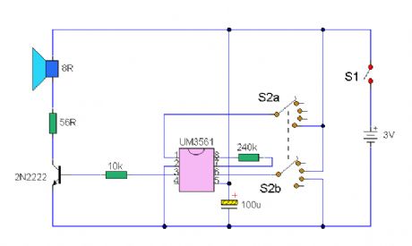
This circuit uses a UM3561 IC to produce four different sound effects. (View)
View full Circuit Diagram | Comments | Reading(0)
Metronome Circuit
Published:2012/11/21 20:55:00 Author:muriel | Keyword: Metronome Circuit
A metronome circuit based on a simple astable. The output sound is distorted to emphasize the pulses. (View)
View full Circuit Diagram | Comments | Reading(1118)
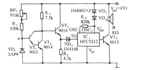
Electronic Canary
Published:2012/11/21 2:16:00 Author:muriel | Keyword: Electronic Canary
An electronic version of a chirping canary. May be used as an alarm, a sound effects generator or perhaps a replacement doorbell. (View)
View full Circuit Diagram | Comments | Reading(1369)
Audio Voice-Over Circuits
Published:2012/11/19 21:43:00 Author:muriel | Keyword: Audio Voice-Over Circuits
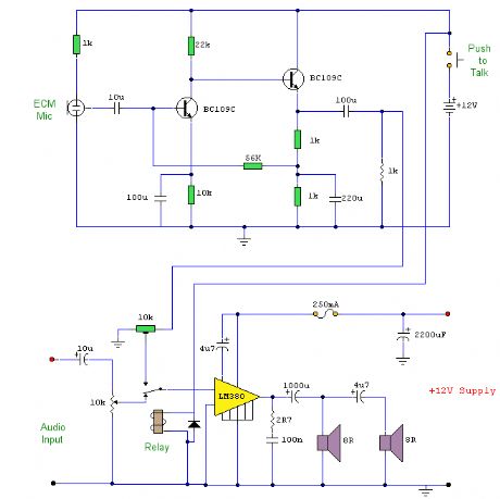
This is a circuit where a microphone and preamp circuit (voice circuit) have priority over any other audio signal. You can think of this as a one way intercom, if the main amplifier is used for listening to music, then when the push to talk switch is pressed, the amplifier is switched to the voice signal. (View)
View full Circuit Diagram | Comments | Reading(1192)
A simple audio power meter circuit using LM3915
Published:2012/10/28 21:11:00 Author:Ecco | Keyword: audio power meter
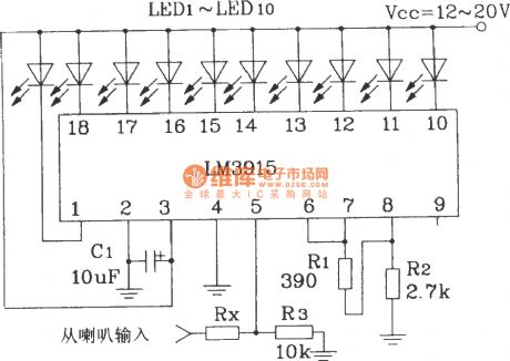
Note: If the speaker internal resistance is 4Ω, Rx takes 10kΩ If the speaker internal resistance is 8Ω, Rx takes 18kΩ If the speaker internal resistance is 16Ω, Rx takes 30kΩIt uses IC to display AC input signal amplitude, and the more perfect method is to use a half - wave converter to change AC signal into DC signal, the DC signal is sent to the input terminal of IC.
(View)
View full Circuit Diagram | Comments | Reading(4598)
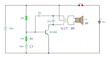
Simple Two-Transistor Radio
Published:2012/10/22 22:07:00 Author:muriel | Keyword: Simple, Two-Transistor, Radio
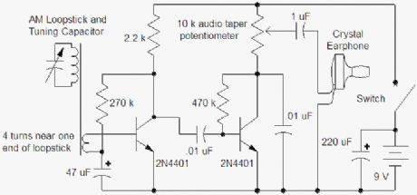
Here is a simple radio that was designed to minimize unusual parts; there isn't even a detector diode! The sensitivity isn't as high as the one-transistor reflex but the simplicity is attractive. Strong stations will provide plenty of volume into a crystal earphone or an external amplifier. The AM Loopstick was purchased on eBay but the enterprising experimenter can swipe one from the interior of a cheap radio. If the loopstick has more than one winding, use the one with the most turns. Wind 3 or 4 turns near one end of the winding as seen in the photo. The tuning capacitor in the prototype is from an old radio and the little plastic dial was cut down such that it just fit into the back of a black pointer knob. The fit was tight so no glue was needed. All of the sections of the capacitor were connected in parallel to get the most capacitance for this loopstick.
All the other parts are common. The transistors can be just about any small-signal type. The prototype uses the metal can 2N2222, primarily for looks. Some transistors may have too much high frequency gain; if the circuit squeals, try adding a small resistor in the emitter of the first transistor, maybe 47 ohms, the smaller the better as long as the circuit is stable. The large 47 uF could be smaller in most cases but the circuit can pick up hum if the wires are too long. Don't leave out the large capacitor across the battery, it provides needed low power supply impedance. (View)
View full Circuit Diagram | Comments | Reading(2758)
| Pages:7/54 1234567891011121314151617181920Under 20 |
Circuit Categories
power supply circuit
Amplifier Circuit
Basic Circuit
LED and Light Circuit
Sensor Circuit
Signal Processing
Electrical Equipment Circuit
Control Circuit
Remote Control Circuit
A/D-D/A Converter Circuit
Audio Circuit
Measuring and Test Circuit
Communication Circuit
Computer-Related Circuit
555 Circuit
Automotive Circuit
Repairing Circuit