
Audio Circuit
Index 18
AMPLITUDE_PROBABILITY_DENSITY_FUNCTION
Published:2009/7/17 9:22:00 Author:Jessie
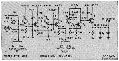
Width of output pulse is proportional to time that input signal is between specified voltage levels. Used in statistical measurements of signals and noise.-B. M. Rosenheck, Detecting Signals By Polarity Coincidence, Electronics, 33:5, p 67-69. (View)
View full Circuit Diagram | Comments | Reading(1049)
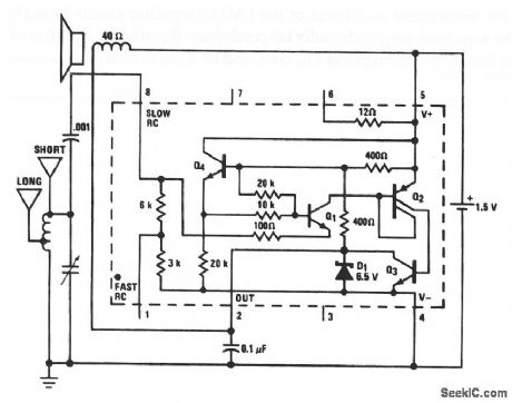
Frequency_sensitive_photo_activated_alarm
Published:2009/7/17 5:07:00 Author:Jessie
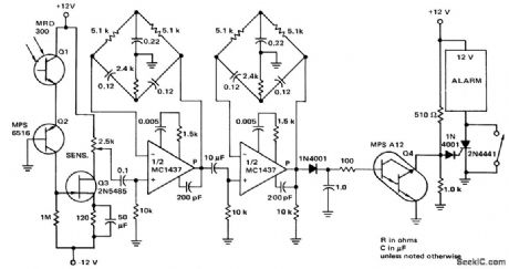
Frequency-sensitive photo-activated alarm (courtesy Motorola Semiconductor Products Inc.). (View)
View full Circuit Diagram | Comments | Reading(945)
DETECTION_IN_NOISE
Published:2009/7/17 5:05:00 Author:Jessie
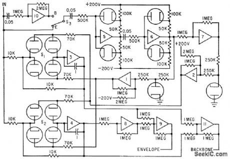
Time derivatives of noise-contaminated input signals control electronic switches which control sampling and holding unit. In mode for detection, signal is sampled at its peaks and troughs. In mode for backbone detection, involving additive noise, signal is sampled at its inflection points.-N. D. Diamantides, Nonlinear Filter Detects Envelope or Backbone, Electronics, 35:18, p 52-54. (View)
View full Circuit Diagram | Comments | Reading(1028)
RADIO_DIRECTION_FINDER_
Published:2009/7/10 4:46:00 Author:May
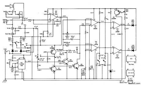
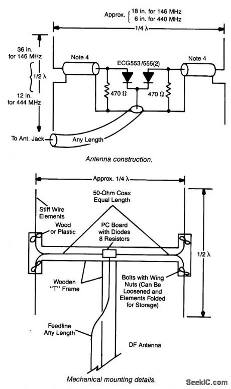
This RDF circuit consists of a square-wave oscillator (IC1), which switches two antennas alternately at an audio rate. A phase detector (Q1, 2, 3, 7) is used to compare receiver output amplified by IC2 with the reference phase from IC2 with the reference phase from IC1. A 50-μA meter is used as a left-right indicator. IC3 is a comparator used to drive indicator LEDs. (View)
View full Circuit Diagram | Comments | Reading(2371)
ZENER_NOISE_GENERATOR
Published:2009/7/17 23:05:00 Author:Jessie
Amplifies noise voltage developed across conducting zener diode. Zener current is fed to base of transistor, which has nominal current gain of 75.-G. Richwell, One-Stage Semiconductor Noise Generator, EEE, 12:7, p 26-28. (View)
View full Circuit Diagram | Comments | Reading(2011)
BACKGROUND_NOISE_SUPPRESSOR
Published:2009/7/17 23:04:00 Author:Jessie
With control set for maximum resistance, only desired a-c voltage peaks above 4.5 V are passed by diodes. Balanced variable-thresh-old circuit achieves this suppression of weak background noise without affecting a-c balance of signals.-W. E. Earle, A-C Threshold Converts to Switch, Electronics, 31;1, p 96-99. (View)
View full Circuit Diagram | Comments | Reading(1176)
SOUND_METER_RECTIFIER
Published:2009/7/17 23:02:00 Author:Jessie
Used with sound level meter to provide indication proportional to rms value of wideband noise, in two-segment linear approximation to required square-law characteristic.-W. V. Richings and B. J. White, Transistorized Sound Level Meter, Electronics, 33:25, p 64-66. (View)
View full Circuit Diagram | Comments | Reading(1354)
SQUELCH_FOR_MOBILE
Published:2009/7/17 23:02:00 Author:Jessie
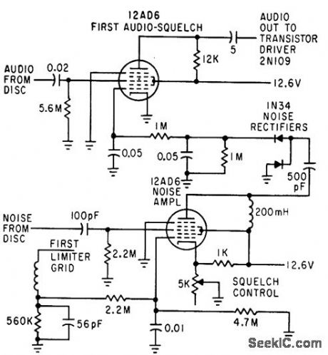
Reduces background noise, to prevent operator fatigue during no-signal periods. Double-action squelch is obtained by using negative voltoge at first limiter grid during signal periods to cut off 12AD6 noise amplifier.-C. Gonzalez and R. J. Nelson, Design of Mobile Receivers with Low-Plate-Potential Tubes, Electronics, 33:34, p 62-65. (View)
View full Circuit Diagram | Comments | Reading(1271)
SQUELCH_FOR_DOUBLE_SUPERHET
Published:2009/7/17 22:42:00 Author:Jessie
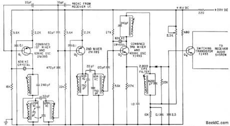
Carrieroperated squelch level is automatically adjusted to best compromise for incoming signal. Squelch can be adjusted to open on 0.5-microvolt input signal while remaining closed when subject to full output of noise generator-J. M. Tewksbury, Receiver Squelch Control Uses Double Superheterodyne, Electronics, 35:3, p 44-46. (View)
View full Circuit Diagram | Comments | Reading(1773)
SCR_NOISE_SUPPRESSOR
Published:2009/7/17 22:40:00 Author:Jessie
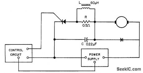
Used to suppress circuit noise generated when scr is switched on, without materially affecting power-handling capacity or efficiency. Load shown is d-c series motor.-Noise Reducer for SCR, EEE, 10:10, p 94. (View)
View full Circuit Diagram | Comments | Reading(1277)
DISTANCE_MARK_GENERATOR_7
Published:2009/7/19 21:07:00 Author:Jessie
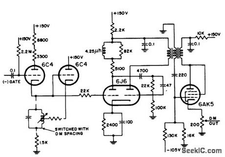
Uses switched Hartley oscillator, mvbr-type trigger shaper, and parallel-triggered blocking oscillator to generate distance marks for 2, 5, and 25 miles in airborne search radar. RLC unit is switched to change mark spacing.-NBS, Handbook Preferred Circuits Navy Aeronautical Electronic Equipment, Vol, 1, Electron Tube Circuits, 1963, p N8-2. (View)
View full Circuit Diagram | Comments | Reading(1524)
AM_radio
Published:2009/7/19 23:21:00 Author:Jessie
This circuit uses the LM3909 as a basic AM radio (chapter 2). The tuned circuit is a standard AM-radio ferrite antenna coil (loopstick with a tap 40% of the turns from one end) and a 360-pF tuning capacitor). The short antenna is 10 to 20' and the long antenna is 30 to 100'. Notice that this radio does not oscillate, and tuning is only as good as a simple crystal set. Because of the low power drain, the circuit will operate continuously for about a month on a single D flashlight cell, and drive a 6 speaker. National Semiconductor, Linear Applications Handbook, 1991 p 405. (View)
View full Circuit Diagram | Comments | Reading(0)
FIVE_TRANSISTOR_AUTO_RADIO
Published:2009/7/19 22:42:00 Author:Jessie
Q1 is r-f amplifier, Q2 is autodyne converter, Q3 is unneutralized 262-kc i-f amplifier or, D1 is audio detector Q4 is audio driver, and Q5 is single-ended output delivering 4 w at less than 10% total distortion. Sensitivity is 2 microvolts at 1 w audio output.-R. A. Santilli and C. F. Wheatley, Transistorizing Automobile Broadcast Receivers, Electronics, 32:38, P 42-45.
(View)
View full Circuit Diagram | Comments | Reading(2210)
VERTICAL_ACCELERATION_RECORDER
Published:2009/7/20 1:40:00 Author:Jessie
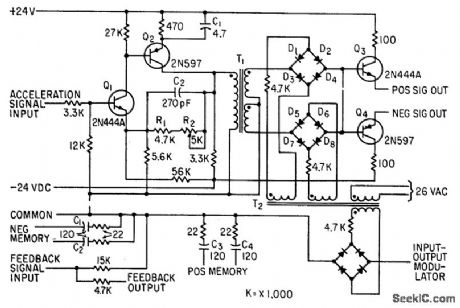
Accepts phase-reversible 40-cps signal from vertical accelerometer, which is in phase with reference voltage for positive accelerations and 180°out of phase for negative. After amplification by Q1-Q2, synchronous demodulator diodes D1 to D8 separate positive and negative signals for output transistors Q3 and Q4, which feed servo of engraved-foil flight recorder.-H. E. Schauwecker, Data Recorder for Airplane Flight Analysis, Electronics, 33:48, p 118-120. (View)
View full Circuit Diagram | Comments | Reading(1469)
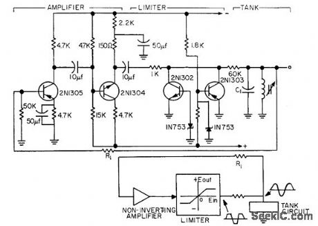
1_CPS_RAIL_FLAW_AMPLIFIER
Published:2009/7/20 1:39:00 Author:Jessie
Used to amplify extremely low-frequency signals produced by longitudinal defects in rails, to drive pen recorder. C1 bypasses high-frequency signals.-H. W. Keevil, Transistor Pulse Amplifiers Detect Rail Faults, Electronics, 35:21, p 53-54. (View)
View full Circuit Diagram | Comments | Reading(1042)
FACSIMILE_SWEEP
Published:2009/7/20 1:36:00 Author:Jessie
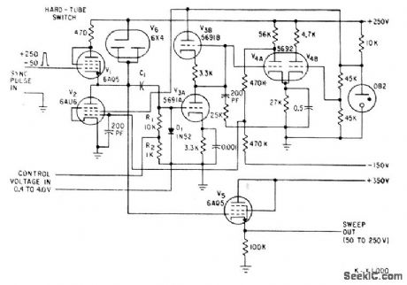
Maximum variation in sweep length is less than 1 part in 1,000. Uses modified Miller feedback circuit. Sweep role can be controlled over 10:1 ratio.-E. W. Van Winkle, High-Precision Sweep Generator, Electronics, 33:50, p 88-90. (View)
View full Circuit Diagram | Comments | Reading(1097)
TRANSDUCER_EXCITER
Published:2009/7/20 1:34:00 Author:Jessie
Used in carrier amp lifer of strip-chart recorder to provide amp litude-stable fixed excitation frequency for transducer. Two-stage amplifier with 360° phase shift oscillates when output is fed to input, al frequency depending on loop parameters. Amplitude variation is held to 0.2% for 25℃ change in ambient by simple zener and transistor limiter.-Amplitude-Stable Audio Oscillator, EEE, 11:8, p 87. (View)
View full Circuit Diagram | Comments | Reading(1464)
RUGGED_DESIGN_FOR_OCEANOGRAPHY
Published:2009/7/20 1:32:00 Author:Jessie
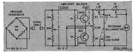
Can drive low-impedance recording galvanometer for long periods without auxiliary power. Bilateral symmetry of push-pull circuit using matched 2N65 transistors optimizes linearity and thermal stability. Although designed for d-c operation, response is fiat within 2 db up to 50 kc.-W. G. Von Dom, Transistor D.C Amplifier for Rugged Use in Field, Electronics, 33:1, p 85. (View)
View full Circuit Diagram | Comments | Reading(1370)
TRACING_CAUSES_OF_LAB_LINE_TRANSIENTS
Published:2009/7/20 1:29:00 Author:Jessie
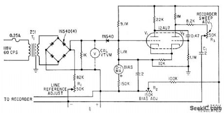
Circuit responds to single pulse having rise time as short as 1 microsec, and records average value of line voltage. Transients greater than preset trigger level pass through diode gate and trip mono, giving current pluse that drives chart recorder pin.-F. Trainor, Transient Recorder Monitors Power Linesto Protect Circuits, Electronics, 34:29, p 74-75. (View)
View full Circuit Diagram | Comments | Reading(1115)
PEAK_READING_CIRCUIT
Published:2009/7/20 1:26:00 Author:Jessie
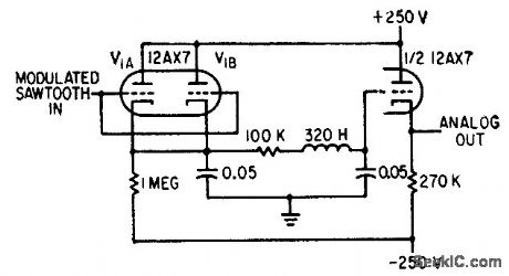
Recovers analog voltage from modulated sawtooth waveform of magnetic-drum recorder.-H. L. Daniels and D. K. Sampson, Magnetic Drum Provides Analog Time Delay, Electronics, 32:6, p 44-47. (View)
View full Circuit Diagram | Comments | Reading(1095)
| Pages:18/54 1234567891011121314151617181920Under 20 |
Circuit Categories
power supply circuit
Amplifier Circuit
Basic Circuit
LED and Light Circuit
Sensor Circuit
Signal Processing
Electrical Equipment Circuit
Control Circuit
Remote Control Circuit
A/D-D/A Converter Circuit
Audio Circuit
Measuring and Test Circuit
Communication Circuit
Computer-Related Circuit
555 Circuit
Automotive Circuit
Repairing Circuit