
Audio Circuit
Index 17
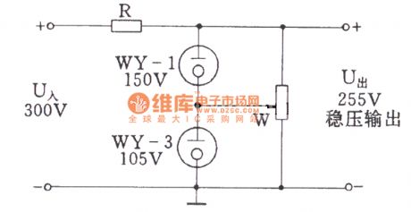
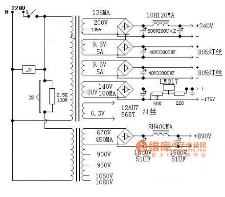
Tube Regulator Circuit
Published:2011/7/17 21:07:00 Author:Felicity | Keyword: Tube Regulator Circuit
View full Circuit Diagram | Comments | Reading(1173)
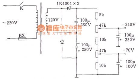
OTL Negative Gate Voltage Doubler Rectifier Circuit (For Tube Amp)
Published:2011/7/17 21:29:00 Author:Felicity | Keyword: OTL Negative Gate Voltage, Doubler Rectifier Circuit, (For Tube Amp)
View full Circuit Diagram | Comments | Reading(2209)
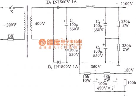
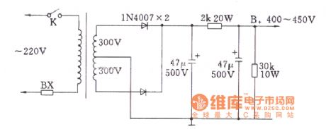
Commonly Used High-voltage Doubler Circuit (For Tube Amp)
Published:2011/7/17 21:16:00 Author:Felicity | Keyword: Commonly Used, High-voltage Doubler, Circuit, (For Tube Amp)
View full Circuit Diagram | Comments | Reading(3030)
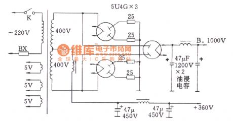
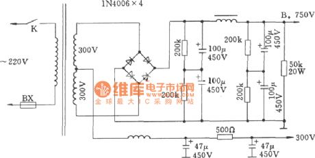
Tube High-voltage Rectifier Bridge Circuit
Published:2011/7/17 20:54:00 Author:Felicity | Keyword: Tube, High-voltage Rectifier, Bridge Circuit
View full Circuit Diagram | Comments | Reading(2048)
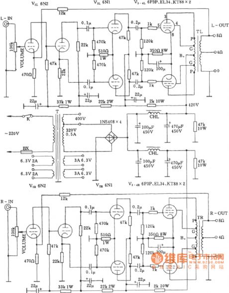
Stereo Power Amplifier Circuit
Published:2011/7/17 20:59:00 Author:Felicity | Keyword: Stereo, Power Amplifier, Circuit
View full Circuit Diagram | Comments | Reading(1265)
Crystal Diode Full-wave Rectifier Circuit (For Tube Amp)
Published:2011/7/17 21:19:00 Author:Felicity | Keyword: Crystal Diode, Full-wave Rectifier, Circuit, (For Tube Amp)
View full Circuit Diagram | Comments | Reading(1633)
Two-channel Amplifier Circuit
Published:2011/7/17 21:00:00 Author:Felicity | Keyword: Two-channel, Amplifier, Circuit

View full Circuit Diagram | Comments | Reading(1210)
Crystal Diode Bridge Rectifier Circuit (For Tube Amp)
Published:2011/7/17 21:26:00 Author:Felicity | Keyword: Crystal Diode, Bridge Rectifier, Circuit, (For Tube Amp)
View full Circuit Diagram | Comments | Reading(2370)
TWO_IC_AM_RADIO
Published:2009/7/16 3:59:00 Author:Jessie
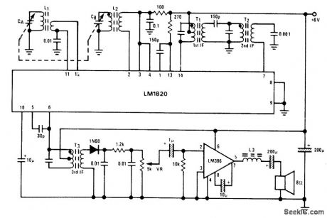
National LM1820 IC serves for RF, oscillator, mixer, and IF stages of AM superheterodyne radio while LM386 IC is audio amplifier driving loudspeaker. Double-tuned circuit at output of mixer provides selectivity. Total gain from base of input stage to diode detector is 95 dB. CA is 140 pF, CB is 60 pF, L1 has 110 and 5 turns for broadcast band, L2 has 98 and 12 turns for oscillator, T1 has 140 turns center tap and 2 turns, T2 has 142 turns and 7 turns, and T3 has 142 turns center tap and 71 turns. IF value is 455 kHz. L3 has 3 turns on ferrite bead. - Audio Handbook, National Semiconductor, Santa Clara, CA, 1977, p 3-4-3-8. (View)
View full Circuit Diagram | Comments | Reading(2680)
160_METERS_TO_l0_METERS
Published:2009/7/16 3:55:00 Author:Jessie
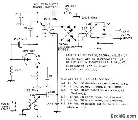
Simple converter adds 160-meter band capability to older CW or AM receiver. Passive mixer is adequate. High output frequency eliminates IF feedthrough and image signals. Crystal oscillates on third over-tone and feeds directly into mixer. -A. Bloom, A Simple 160-Meter Converter, QST, Feb. 1975, p46. (View)
View full Circuit Diagram | Comments | Reading(1426)
SINGLE_COIL_ORYSTAL_RADIO
Published:2009/7/12 23:45:00 Author:May
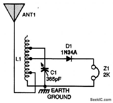
A starting setup for this circuit is as follows:Connect the antenna to the second tap up from the bottom of the coil (that's the end of the coil that's connected to ground). The diode should connect to about the fourth tap up from the bottom, and C1 should be attached to the seventh tap or so up from the bottom. Those tap positions might not be the best starting point for your antenna/ground arrangerttent. That doesn't matter, however, because to obtain the best results with the receiver at your location, you should experiment with all variables anyway. (View)
View full Circuit Diagram | Comments | Reading(1566)
AUDIO_BOOST
Published:2009/7/16 6:29:00 Author:Jessie
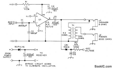
LM380 power amplifier operating on 12 V is well suited for communication receiver having only limited audio gain. Circuit provides excellent headphone volume and enough loudspeaker output for small room. If signal at full secondary winding of product detector AF coupling transformer in receiver overloads U1, take signal from center tap of transformer winding that feeds volume control in amplifier.-H. L. Ley, Jr., More Audio for QST Course Receiver, QST, Oct. 1977, p 45. (View)
View full Circuit Diagram | Comments | Reading(1699)
TWO_CHIP_AM_RADIO
Published:2009/7/16 6:20:00 Author:Jessie
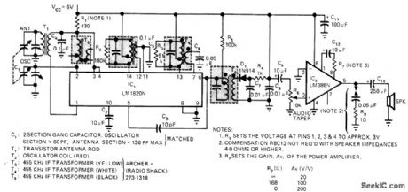
Current drain of only 10mA makes operation from 6-V battery feasible. National LM1820N IC serves for oscillator/mixer, two IF stages, and AGC, and LM386N AF chip provides power output of 0.25 W into 8-ohm loudspeaker. D1 is diode detector.-E. S. Papanicolaou and H. H. Mortensen, Low Cost AM Radio Uses Only Two IC's, EDN Magazine, Jan. 20, 1976, p 82 and 84. (View)
View full Circuit Diagram | Comments | Reading(2128)
12AU7 +5687 Push 845 Push-pull Amplifier Circuit
Published:2011/7/18 4:50:00 Author:Felicity | Keyword: 12AU7 +5687 Push, 845 Push-pull, Amplifier Circuit
View full Circuit Diagram | Comments | Reading(3002)
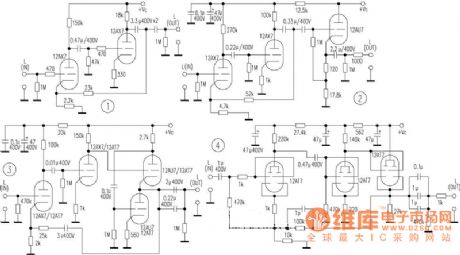
Bile Former Grade Circuit Of Good Performance
Published:2011/7/17 23:41:00 Author:Felicity | Keyword: Bile Former Grade, Good Performance
View full Circuit Diagram | Comments | Reading(1057)
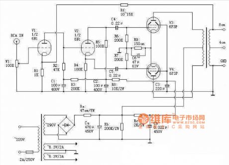
6P3P Push-pull Tube Amp Circuit
Published:2011/7/17 23:43:00 Author:Felicity | Keyword: 6P3P, Push-pull, Tube Amp Circuit
View full Circuit Diagram | Comments | Reading(5194)
SIMPLE_AM_RADIO
Published:2009/7/17 2:33:00 Author:Jessie
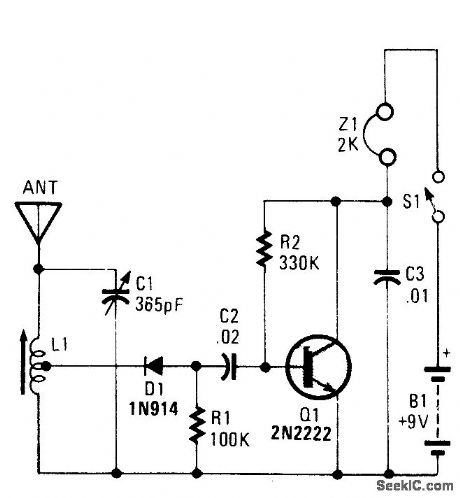
An AM radio can be built of a simple diode detector and an audio amplifier. A random length of wire always serves as an antenna. L1 is an adjustable ferrite loopstick of the type used in transistor radios. (View)
View full Circuit Diagram | Comments | Reading(3711)
MOTOR_CONTROLLING_MIXER
Published:2009/7/11 2:10:00 Author:May
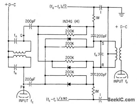
Used to lock crystal oscillator frequency to standard-frequency signals from WWV. Circuit mixes dock and WWV frequencies (fed to tubes at left and right) in Nygaard discriminator ar rangement, which delivers two outputs, each equal to difference frequency but differing 90°in phase. These output signals are amplified for synchronous motor that drives trimmer capacitor of crystal oscillator in servo loop that brings difference frequency to zero.-K.Nygaard, Atomic Clock Accuracy for Crystal Oscillators, Electronics, 33:46, p82-83. (View)
View full Circuit Diagram | Comments | Reading(1070)
4_bit_look_ahead_carry_adder_using_an_MC10179_and_four_MC10180s
Published:2009/7/17 3:26:00 Author:Jessie
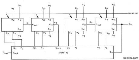
4-bit look-ahead carry adder using an MC10179 and four MC10180s (courtesy Motorola Semiconductor Products Inc.). (View)
View full Circuit Diagram | Comments | Reading(1674)
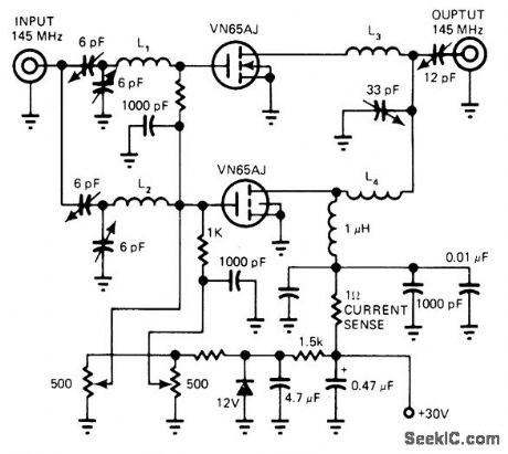
RECEIVER_FRONT_END_RF_ATTENUATOR
Published:2009/7/17 3:24:00 Author:Jessie
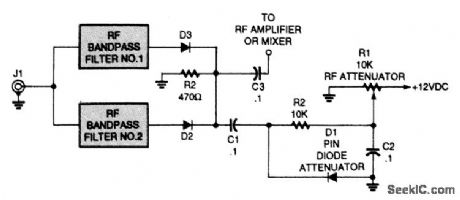
This PIN-diode front-end RF attenuator circuit contains a simple shunt circuit. The dc voltage from the potentiometer sets the attenuation level. The PIN diodes can be MV3404 or similar types. (View)
View full Circuit Diagram | Comments | Reading(1192)
| Pages:17/54 1234567891011121314151617181920Under 20 |
Circuit Categories
power supply circuit
Amplifier Circuit
Basic Circuit
LED and Light Circuit
Sensor Circuit
Signal Processing
Electrical Equipment Circuit
Control Circuit
Remote Control Circuit
A/D-D/A Converter Circuit
Audio Circuit
Measuring and Test Circuit
Communication Circuit
Computer-Related Circuit
555 Circuit
Automotive Circuit
Repairing Circuit