
Audio Circuit
Index 16
160_METER_CONVERTER
Published:2009/7/15 5:17:00 Author:Jessie
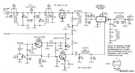
Designed for use with receiver covering 20-meter band. Uses up-conversion techniques to get from 1.8 MHz of 160-meter band to 14-MHz tunable IF of receiver. Butterworth band pass filter at input of converter covers 1.8-1.9 MHz. L1 and L2 each have 31 turns No. 22 enamel on T68-6 toroid core to give 5.1 μH. L3 is 50 μH, using 66 turns No. 18 enamel on T68-1 toroid. Other three coils each use T50-6 toroid core, with L4 having 7 turns No. 24 enamel, L5 11 turns No. 24 enamel, and L626 turns No. 28 enamel. U1 is SRA-1, CM-, or ML-1 diode-quad double-balanced mixer module. -M. Arnold and D. DeMaw, Build This High-Performance Top-Band Converter, QST, Oct. 1978, p 22-24 and 38. (View)
View full Circuit Diagram | Comments | Reading(3280)
152_165_MHz_TO_14694_MHz
Published:2009/7/15 5:16:00 Author:Jessie
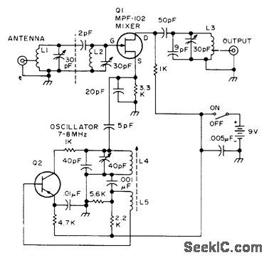
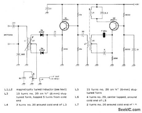
Permits listening to public service band with any good 2-meter FM receiver or transceiver. Local oscillator has tuning range of 7-8 MHz and uses germanium PNP high-frequency transistor. No RF stage is needed for full quieting from stations 10 miles away when using ground-plane antenna. To avoid burning out convener, do not transmit while converter is connected to transceiver. Article gives coil-winding data. -H. Schoenbach, Public Service Band Converter, 73 Magazine, Dec. 1974, p 78-79 (View)
View full Circuit Diagram | Comments | Reading(2199)
28_MHz_TO_144_MHz
Published:2009/7/15 5:15:00 Author:Jessie
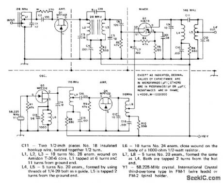
Addition of small upconverter, between 145.85 and 145.95 MHz, is fed verter to 144-MHz (2-meter) SSB transceiver to antenna terminal of receiver.-T. McMullen, permits reception of 10-meter signals from An Up Converter for Oscar Reception, QST, Oscar satellite on single transceiver. Output of March 1975, p 41-44. (View)
View full Circuit Diagram | Comments | Reading(2634)
175_kHz_TO_1515_OR_3515_kHz
Published:2009/7/15 5:12:00 Author:Jessie
Crystal-controlled VLF converter covering 1750-meter band gives choice of two outputs, selected by S2, for communication or broadcast receiver. Tuning range is 160 to 190 kHz. Connect general-coverage receiver to IF output terminals with length of coax. -J. V. Hagan, A Crystal-Con-trolled Converter and Simple Transmitter for 1750-Meter Operation, QST, Jan. 1974, p 19-22. (View)
View full Circuit Diagram | Comments | Reading(2534)
55_MHz_TO_455_kHz
Published:2009/7/15 5:04:00 Author:Jessie
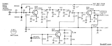
Developed for use as second converter in all-band double-conversion superheterodyne receiver for AM, narrow-band FM CW, and SSB operation. IF amplifier Q23 is followed by triple-tuned filter feeding second mixer Q24, with Q25 as crystal oscillator. Supply is 13.6 V regulated. Article gives all circuits of receiver.-D M Eisenberg, Build This All-Band VHF Receiver, 73 Magazine, Jan, 1975, p105-112 (View)
View full Circuit Diagram | Comments | Reading(3985)
SINGLE_IC_RADIO
Published:2009/7/15 23:02:00 Author:Jessie
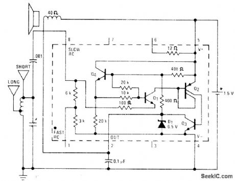
National LM3909 IC is connected as detector-amplifier driving loud-speaker, with extremely low power gain giving continuous operation for 1 month from D cell. Tuning capability is comparable to that of simple crystal set. Provides acceptable volume from local station if used with efficient 6-inch 40-ohm loudspeaker. Coil is standard AM radio ferrite loopstick having tap 40% of turns from one end. Short antenna can be 10-20 feet, and long antenna can be 30-100 feet.- Linear Applications, Vol. 2, National Semiconductor, Santa Clara, CA, 1976, AN-154, p 8-9. (View)
View full Circuit Diagram | Comments | Reading(1639)
PREFERRED_VIDEO_LIMITER
Published:2009/7/15 23:20:00 Author:Jessie
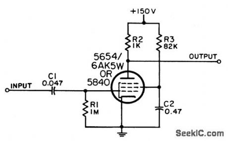
Used to amplify and limit low-level video signals. Capable of handling very fast rise times. Maximum duty factor is 4%. Limiting level is within 35% of 4.8 V, depending on variations in tube and components.-NBS, Handbook Preferred Circuits Navy Aeroncautical Electronic Equipment, Vol. 1, Electron Tube Circuits, 1963, PC 21, p 21-2. (View)
View full Circuit Diagram | Comments | Reading(1152)
BINARY_COUNTER
Published:2009/7/13 23:26:00 Author:May
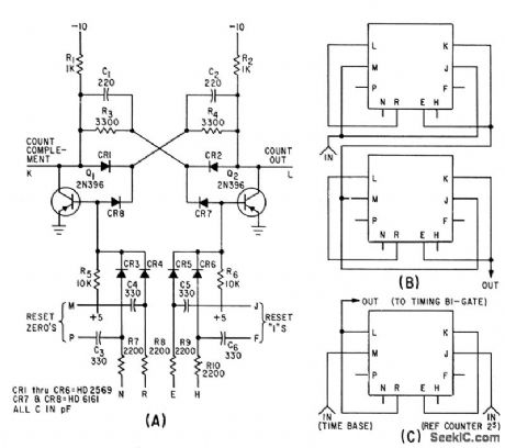
Basic binary circuit can be used alone as at A for counting up to 130 kc. Two circuits connected as at B give lip-fop operation, while one circuit with external connections as in C serves as bistable gate.-K. H. Brackney und D. R. Gosch, Pulse Comparator Circuit Measures Frequency Jitter, Electronics, 34:27, p 54-56. (View)
View full Circuit Diagram | Comments | Reading(2053)
TRANSMIT_MIXER
Published:2009/7/13 22:28:00 Author:May
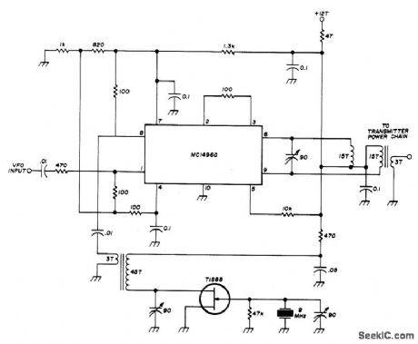
Used in low-power transceiver for 20-meter amateur band. VFO input, tunable from 5 to 5.55 MHz, is combined with 9-MHz output of crystal oscillator in Motorola MC1496G double-balanced modulator to give 14-MHz output for transmitter power chain. Supply voltage (+12 V) is applied only when transmitting. Transformers are wound on Amidon T-50-6 toroids or equivalent. Balance is Balance is maintained in mixer with center-tapped tuned circuit in output, made by putting 15-turn bifilar winding on toroid core and tuning series combination. Article gives all other circuits of transceiver.-W. Hayward, Low-Power Single-Band CW Transceiver, Ham Radio, Nov. 1974, p 8- 1 7. (View)
View full Circuit Diagram | Comments | Reading(2456)
DOUBLE_BALANCED_MIXER
Published:2009/7/13 22:23:00 Author:May
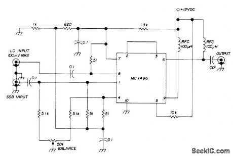
Used in 80-meter SSB transceiver on both transmit and receive. Local oscillator input of 5-5.5 MHz is pro-vided by VFO. SSB signal for receive comes from two-stage MOSFET RF amplifier-D. Hembling, Solid-State 80-Meter SSB Transceiver, Ham Radio, March 1973, p 6-17.
(View)
View full Circuit Diagram | Comments | Reading(0)
PASSIVE_LONGWAVE
Published:2009/7/16 3:22:00 Author:Jessie
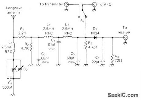
Uses VFO of amateur-band transmitter to supply heterodyne for bringing in frequencies below 450-kHz broad-cast band on amateur receiver, such as Omega navigation station on 10.2-13.6 kHz, NAA Teletype on 17.8 kHz, and GBR time signals on 16 kHz. L1-C1-C2 100.kHz input wavetrap for loran C can be omitted at far-inland locations. C2 is two-gang broadcast variable capacitor with both sections in parallel. Mount L2 at right angle to L3. Converter should be well shielded. Operation involves tuning receiver to bottom of any amateur radio band, on frequency equal to difference between VFO and that to which receiver is tuned. If VFO is on 7 MHz and receiver is tuned to 7.085 MHz, combination will be set for 85-kHz station. In USA, unlicensed transmission on 160-190 kHz is permitted with 1-W input and 50-foot antenna including length of transmission line. -M. Muench, Longwave Simplified, CQ, March 1976, p 41-42. (View)
View full Circuit Diagram | Comments | Reading(1912)
100_200_kHz_TO_18_2_MHz
Published:2009/7/16 3:18:00 Author:Jessie
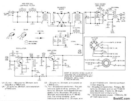
High-performance low-frequency converter picks up experimental CW, SSB, RTTY, and beacon signals in 160-190 kHz band for conversion to tunable IF range of modern communication receiver. Double-balanced diode-ring mixer has conversion loss of 6-8 dB and will stand up against strong signals without causing overloading and cross-modulation. Use 1N914 matched diodes. Diplexer at mixer output is tuned to 3 times converter IF. Article covers construction and alignment. -D. DeMaw, A High-Performance Low-Frequency Converter, QST, June 1977, p 23-26. (View)
View full Circuit Diagram | Comments | Reading(4454)
TUNABLE_VLF
Published:2009/7/16 3:16:00 Author:Jessie
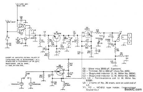
TUNABLE VLF-Gives tuning range of 10kHz to 150 kHz without bandswitching, for WWV transmissions on 20 and 60 kHz and for operation on no-license amateur band around 1750 meters. Uses inductive tuning with toroidal ferrite core L1-L2 that is magnetically biased by pair of 1/2-inch diameter button-type permanent magnets. Rotating one of magnets with respect to other varies flux through toroid, changing its permeability and inductance. Toroid uses 100 turns of stranded wire to give inductance variation from 100 μH to 12 mH (120:1 range). Ferrite cores with higher permeability require fewer turns. Converter output on 15 meters feeds into communication receiver. Local oscillator uses FT-243 7-MHz crystal in third-over-tone mode to give 21 MHz. Antenna is directly coupled or coupled through capacitor to improve matching to long antenna. -G. Ruehr, Tuned Very Low-Frequency Converter, Ham Radio, Nov. 1974, p 49-51.1 (View)
View full Circuit Diagram | Comments | Reading(2645)
MOS_FET_MIXER
Published:2009/7/13 6:13:00 Author:May
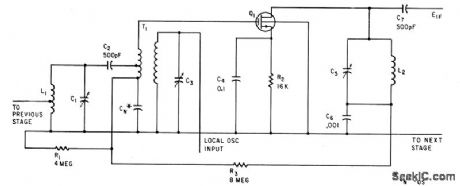
Balanced oscillator input prevents interaction between tuned circuits. Transconductance of mixer is direcdy proportional to oscillator voltage, permitting use for agc. -G. G. Luettgenau and S. H. Barnes, Designing With Low-Noise MOS FETs: A Little Different But No Harder,Electronics,37:31,p53-58 (View)
View full Circuit Diagram | Comments | Reading(1223)
255_MC_OSCILLATOR_MlXER
Published:2009/7/13 5:24:00 Author:May
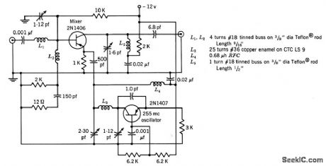
Conversion gain is 20 db and i-f output is 30 Mc.-Texas Instruments Inc. Transistor Circuit Design, McGraw-Hill, N.Y.1963, p326. (View)
View full Circuit Diagram | Comments | Reading(1256)
42O_MC_OSCILLATOR_MIXER
Published:2009/7/13 5:10:00 Author:May
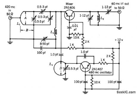
Common-base mixer is used with 480-Mc oscillator to give 60-Mc i-f output, with 10 db average conversion gain.-Texas Instruments Inc. Tran-sistor Circuit Design, McGraw-Hill, N.Y. 1963, p327. (View)
View full Circuit Diagram | Comments | Reading(1414)
LOW_NOISE_LOW_LEVEL_AUDIO_AGC
Published:2009/7/16 2:37:00 Author:Jessie
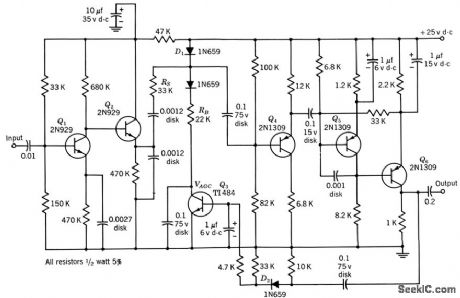
Q1 and Q2 are active amplifier elements.Agc range is 60 db, maximum output signal is 1 v, and maximum input signal is 2 mv. Noise figure is 6 db. Agc circuit here uses shunting diode D1.-Texas Instruments Inc., Transistor Circuit Design, McGraw-Hill, N.Y., 1963, p 179. (View)
View full Circuit Diagram | Comments | Reading(2215)
CB_TRANSMITTER_MIXER
Published:2009/7/13 4:58:00 Author:May
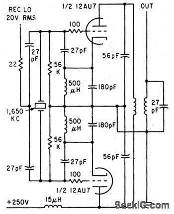
Requires only one crystal per channel in 27-Mc citizens band radiotelephones, by combining beating oscillator with balanced mixer. Receiver local oscillator with balanced mixer.Receiver local oscilator signal and even harmonics of beating oscillator frequency are cancelled in tuned symmetrical plate circuit.-M. E. Baird, Mixer Circuit Lowers Radiotelephone Costs, Electronics,34:47, p71. (View)
View full Circuit Diagram | Comments | Reading(1371)
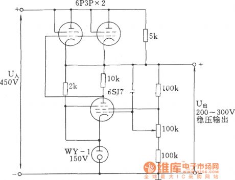
High-current Voltage Regulator Tube Circuit
Published:2011/7/17 21:08:00 Author:Felicity | Keyword: High-current, Voltage Regulator, Tube Circuit
View full Circuit Diagram | Comments | Reading(3159)
BALANCED_INPUT_MIXER
Published:2009/7/13 4:40:00 Author:May


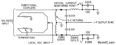
Used with frequency-independent antennas to provide noise cancellation as balanced-input converter.-C. Strother, Jr. and C. R. Lundquist, Balinverter-Frequency-Insensitive Balanced Converter, Electronics, 35:44, p46-47. (View)
View full Circuit Diagram | Comments | Reading(1245)
| Pages:16/54 1234567891011121314151617181920Under 20 |
Circuit Categories
power supply circuit
Amplifier Circuit
Basic Circuit
LED and Light Circuit
Sensor Circuit
Signal Processing
Electrical Equipment Circuit
Control Circuit
Remote Control Circuit
A/D-D/A Converter Circuit
Audio Circuit
Measuring and Test Circuit
Communication Circuit
Computer-Related Circuit
555 Circuit
Automotive Circuit
Repairing Circuit