
Audio Circuit
Index 9
Audio Clipping Indicator
Published:2012/9/26 21:18:00 Author:muriel | Keyword: Audio Clipping, Indicator
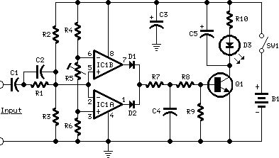
This Audio Clipping Indicator circuit was intended to detect clipping in preamp stages, mixers, amplifiers etc. and can be used as a separate, portable unit, to signal by means of a LED when the output wave form of a particular audio stage is “clipping” i.e. is reaching the onset of its maximum permitted peak-to-peak voltage value before an overload is occurring. This will help the operator in preventing severe, audible distortion to be generated through the audio equipment chain.This unit is particularly useful in signaling overload of the input stages in mixers, PA or musical instruments amplification chains, but is also suited to power amplifiers. A careful setting of Trimmer R5 will allow triggering of the LED with a wide range of peak-to-peak input voltages, in order to suit different requirements.
Unfortunately, an oscilloscope and a sine wave frequency generator are required to accurately setup this circuit. Obviously, the unit can be embedded into an existing mixer, preamp or power amplifier, and powered by the internal supply rails in the 9 – 30V range. The power supply can also be obtained from higher voltage rails provided suitable R/C cells are inserted. SW1 and B1 must obviously be omitted.
Clipping Indicator circuit diagram
(View)
View full Circuit Diagram | Comments | Reading(1780)
Audio Mixer with one transistor
Published:2012/9/20 20:59:00 Author:Ecco | Keyword: Audio Mixer , one transistor
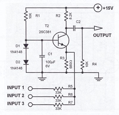
This one transistor audio mixer is used in an amplifier circuit design with base driven transistor and with its emitter being current controlled, most of the driving current flows through the collector away. Using the values in the audio mixer circuit shown in the diagram, the collector current will be about 1 mA. At 15 volts power supply, the input resistors should be 33K. Additional input lines can be connected to the emitter line. Each added input must be series limited by the 33K resistor.
Audio mixer circuit diagram
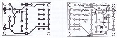
Mixer PCB Layout
(View)
View full Circuit Diagram | Comments | Reading(3457)
Cheap Metal Detector circuit
Published:2012/9/19 21:42:00 Author:Ecco | Keyword: Cheap , Metal Detector
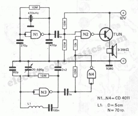
The working principle of this cheap and easy to build metal detector circuit consists in mixing two equal frequencies which causes a low-frequency interference. When one of the oscillators become unstable then the frenquency of the interference will be modified. The metal detector circuit is built with CD4011. The oscillator is built with NAND N1 and a ceramic filter of intermediary freq. (470kHz). The second oscillator is with N3 and a LC combination. The freq. of this osc. is adjusted in such way that will produce an audible oscillation of both freqs.Thru N4, the signal from the variable osc. is amplified. If the sensor coil L1 is closer to a metal object then it will modify the auto-induction of the coil, the osc. is unbalanced and the sound will modify.The metal detector’s coil is made of: 70 turns of enamelled copper with diam. of 0.3-0.6 mm on a 5 cm diam.
Easy to build metal detector schematic
?
4 Responses to “Cheap Metal Detector circuit”
Source: electroschematic.com
(View)
View full Circuit Diagram | Comments | Reading(1488)
Audio Processor Circuit
Published:2012/9/19 21:21:00 Author:Ecco | Keyword: Audio Processor
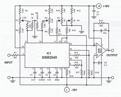
This audio processor circuit features the SSM2045 IC which was developed specially for electronic music applications and the 741 opamp IC. The circuit is configured as a low pass filter with a DC voltage control for gain. The input signal is set to a working level of 150mVpp through the resistor R1.How does the audio processor works
The filter has 2 buffered outputs: the 2-pole output at pin 1 and 4-pole output at pin 8. Internally, the outputs are connected to 2 voltage-controlled-amplifiers (VCA).The R15 and R16 are connected to these outputs to achieve optimum offset and control voltage suppression.
P4 is the volume control. The current that flows to the pins 15 and 16 should not go beyond the maximum of 250 µA. The balance of the two VCAs and the entire filter is being controlled be a voltage range of -250 mV to + 250 mV at pin 14.This voltage can be set by P2.
The input can be driven with source impedances up to a maximum of 200 Ω. With an input level of 0dBm, the VCA weakens by 6 dB. The bias current needed at pin 17 is between 120 µA and 185 µA. The cutoff frequency can be shifted between 20 Hz and 20 kHz with a variable voltage at pin 5. This can be varied through P1. The capacitor values were selected to give the filter its Butterworth characteristics.
The output current of the SSM2045 IC is converted to a voltage output by the 741 opamp. Any sybsequent circuit must be DC decoupled from IC2.The noise-voltage ration is about 80 dB.
Audio processor circuit schematic
Sent by Claudio, IT
3 Responses to “Audio Processor Circuit”
(View)
View full Circuit Diagram | Comments | Reading(1852)
1W stereo Headphone Amp (TDA2822)
Published:2012/9/13 20:54:00 Author:Ecco | Keyword: 1W , stereo Headphone Amp
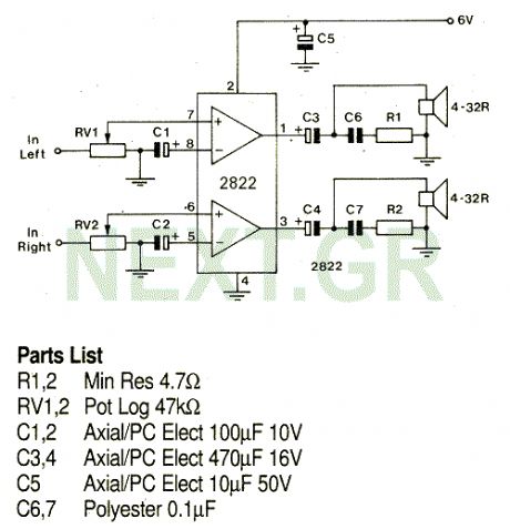
A stereo power amp designed for use in portable players and radios. A 3V supply can be used to drive headphones providing 20mW in 32 Ohms per channel.
Source: NEXT.GR (View)
View full Circuit Diagram | Comments | Reading(0)
Microphone Preamplifier with SSM 2015 P
Published:2012/9/13 3:51:00 Author:Ecco | Keyword: Microphone, Preamplifier, SSM
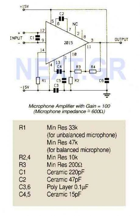
An ultra low noise audio preamplifier particularly suited to microphone preamplification including balanced microphones. The IC features wide bandwidth, low distortion only 0.007% at a gain of 100.
Source: NEXT.GR (View)
View full Circuit Diagram | Comments | Reading(1851)
Magnetic Cartridge Preamplifier (LT1028CN8)
Published:2012/9/13 3:43:00 Author:Ecco | Keyword: Magnetic Cartridge , Preamplifier
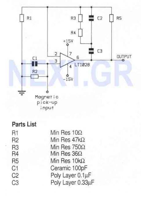
A high performance op-amp that sets a new standard of excellence in noise performance only 0.9nV/Hz with low source resistances. Total harmonic distortion is less than 0.01%. The op-amp is suitable for use in high quality audio, low noise frequency synthesizers, infrared detectors etc.
Source: NEXT.GR (View)
View full Circuit Diagram | Comments | Reading(1213)
Small leakage pre-amplifier
Published:2012/9/11 21:30:00 Author:Ecco | Keyword: Small leakage, pre-amplifier
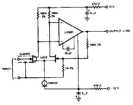
The circuit uses the LM301 has an input leakage of only 2 pA typical at 75 ° C and is used with 1 M ohm input resistance. The operating voltage has to be +-12V. (View)
View full Circuit Diagram | Comments | Reading(0)
Audio compressor circuit
Published:2012/9/11 21:22:00 Author:Ecco | Keyword: Audio compressor
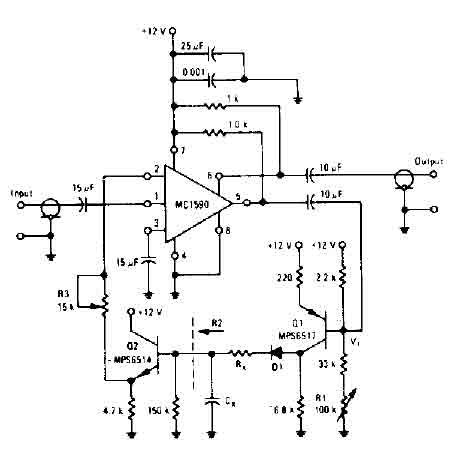
The amplifier drives the base of a common emitter PNP MPS6517 operating with a voltage gain of about 20. RL control varies the quiescent point of the transistor Q, so that varying amounts of signal exceed the level of V r, diode D 1 rectifies the positive peaks Ql output is only when these peaks are more larger than r V ' 7. 0 volts. The result is filtered ex Rx. s, controls the charging time constant or time of attack. Cx is involved in two loading and unloading. R2 (150 K, the input resistance of the emitter-follower Q2) controls the decay time. (View)
View full Circuit Diagram | Comments | Reading(0)
RIAA preamplifier CA3410
Published:2012/9/11 21:02:00 Author:Ecco | Keyword: RIAA , preamplifier
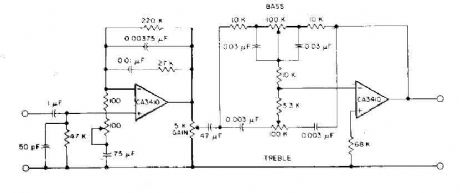
This circuit has read the RIAA equalization, tone controls, and adequate gain to drive most power amplifiers conunercial by using CA3410 op amp BiMOS. Total harmonic distortion, pushed to provide an output of 6-V, is less than 0.035% in audio-frequency range from 150 Hz to 40 kHz. Full stereo preamp is to duplicate this circuit using the CA3410 remaining two amplifiers. (View)
View full Circuit Diagram | Comments | Reading(0)
4 microphones mixer circuit with TL081
Published:2012/9/11 20:29:00 Author:Ecco | Keyword: 4 microphones , mixer
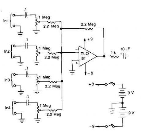
A TL081 op amp is used as a high impedance to low. converter and a signal mixer. The input impedance is about 1 megohm and the output impedance is about 1 kohm. Two 9 volt batteries are used as power source. (View)
View full Circuit Diagram | Comments | Reading(0)
Fully adjustable preamplifier
Published:2012/9/11 20:28:00 Author:Ecco | Keyword: Fully adjustable , preamplifier
This circuit is a audio preamplifier tha has balance, tone and loudness controls. It should be suitable as an example of good design for audio application. Uses the BAA730 and NE540 chips. (View)
View full Circuit Diagram | Comments | Reading(0)
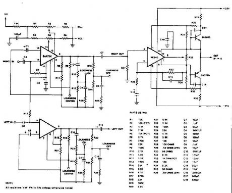
Stereo Preamplifier with balance and loudness
Published:2012/9/11 20:27:00 Author:Ecco | Keyword: Stereo Preamplifier , balance , loudness
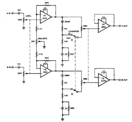
The circuit of preamplifier use the 5533 chip and features a combination of controls balance and volume. Due to the nonlinearity of the human auditory system, low frequencies must be boosted at low listening levels. Level pay, and LOUDNESS controls provide all the plays to produce the desired response from the music. (View)
View full Circuit Diagram | Comments | Reading(0)
Microphone preamplifier with TLC251
Published:2012/9/11 20:19:00 Author:Ecco | Keyword: Microphone, preamplifier
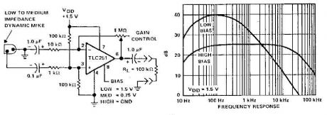
A microphone preamplifier using: om CMOS op amp with its own battery, is small enough to be placed in a case of small microphone. The amplifier operates from a 1.5V battery cathode mercury low supply currents. This preamp will operate at very low power and maintain a reasonable frequency response as well. The TLC251 is operating in low bias (operating at 1.5 V) draws a supply current of only 10 and has a year - frequency response of 3 dB 27 Hz to 4.8 kHz. With 8-pin grounded, which is designated as the polarization state high limit increases above 25 kHz. Supply current is only - 30 pA under these conditions. (View)
View full Circuit Diagram | Comments | Reading(0)
Automatic audio fader circuit
Published:2012/9/11 20:18:00 Author:Ecco | Keyword: Automatic, audio fader
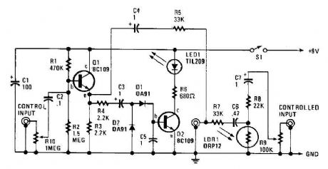
The automatic fader drops at the background music while the narration is in place. The control input through RIO, a preset audio level control, into an emitter-follower buffer stage CQI). The buffer provides high input impedance and ensures that the source impedance is low enough to drive the rectifier and smoothing circuit, consisting of DI, D2, and C5. The smoothed output drives a simple LED circuit. LD and R8 form an IR input pad through which the output is fed through C6 and C7 to the output jack. .. (View)
View full Circuit Diagram | Comments | Reading(0)
One transistor audio mixer (2N3563)
Published:2012/9/10 21:26:00 Author:Ecco | Keyword: One transistor , audio mixer
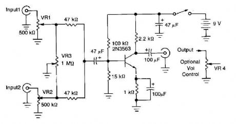
This circuit mixer has an internal amplification with 2N3563 transistor. The two input signals can be independently controlled by VRI and VR2. The VR3 balance control is used to remove a signal while the other melted. (View)
View full Circuit Diagram | Comments | Reading(6068)
4 microphones mixer circuit with TL081
Published:2012/9/10 21:25:00 Author:Ecco | Keyword: 4 microphones

A TL081 op amp is used as a high impedance to low. converter and a signal mixer. The input impedance is about 1 megohm and the output impedance is about 1 kohm. Two 9 volt batteries are used as power source. .. (View)
View full Circuit Diagram | Comments | Reading(0)
Audio input selector circuit (4416 CMOS)
Published:2012/9/10 21:20:00 Author:Ecco | Keyword: Audio input , selector, CMOS
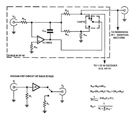
CMOS switches are used directly to select the entries in the audio circuits, it can introduce unacceptable levels of distortion, but if the switch is included in the feedback network of an op amp, the distortion due to the switch may be virtually eliminated. The circuit uses a CMOS switch 4416, arranged as two independent SPDT switches. If switching transients are unimportant, R5 and C1 can be omitted, and R4 may be short-circuited. (View)
View full Circuit Diagram | Comments | Reading(3138)
4 channel audio mixer with TL074
Published:2012/9/10 21:19:00 Author:Ecco | Keyword: 4 channel , audio mixer
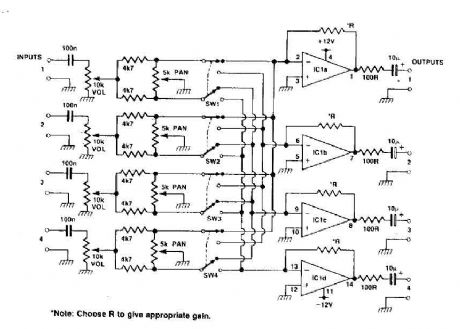
This circuit can be used as a mixer and a stereo track four. The quad op-RNAP IC gives a little gain for each track, the pan control provides panning between one and two tracks with the switch to high, and with the switch to low, it is possible to pan between the tracks and three four channels can be added. (View)
View full Circuit Diagram | Comments | Reading(8012)
Low distortion audio gain limiter
Published:2012/9/10 21:18:00 Author:Ecco | Keyword: Low distortion , audio gain , limiter
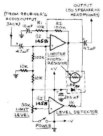
The level at which the limiter kicks in audio can be adjusted with the selector knob LIMIT LEVEL. When this level is exceeded, the output of the half-LIMITING detector of the op-amp (used as a comparator) turns the LED causes the resistance of the photoresistor to decline rapidly. It is in tum causes the gain of Ie half LIMITED op-amp to decrease. (View)
View full Circuit Diagram | Comments | Reading(3100)
| Pages:9/54 1234567891011121314151617181920Under 20 |
Circuit Categories
power supply circuit
Amplifier Circuit
Basic Circuit
LED and Light Circuit
Sensor Circuit
Signal Processing
Electrical Equipment Circuit
Control Circuit
Remote Control Circuit
A/D-D/A Converter Circuit
Audio Circuit
Measuring and Test Circuit
Communication Circuit
Computer-Related Circuit
555 Circuit
Automotive Circuit
Repairing Circuit