
Index 42
TTL_GO_NO_GO_TESTER
Published:2009/7/11 4:26:00 Author:May
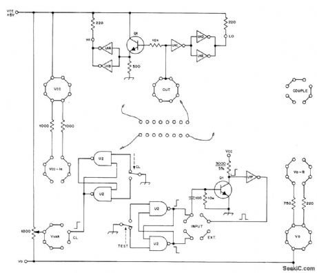
Test panel provides fast static test of surplus 7400 series TTL ICs. Each contact of 16-pin DIP socket has lead that can be plugged into array of seven othersockets carrying various supply voltages, loads, etc. Switches provide pulses of input current for toggling or clocking, counting, and resetting. Leads also serve for cross-coupling gates in IC to make flip-flop and forsetting up other simple circuits. Input voltage control allows plotting of transfer functions and study of circuit operation under different signal-level conditions. Extemal test meter can be connected when necessary. HI and LO indicators are LEDs that show level of terminal connected to output socket. Transistors are general-purpose NPN such as 2N2926. U1 is SN7404 hex inverter, and U2 is SN7400 quad two-input NAND gate. Tester is not suitable for complementary MOS devices requiring protection from static charges. Article gives detailed instructions for testing each type of TTL device.-J. S. Worthington, A Simple TTL Test Panel, QST, Dec. 1976, p 25-27. (View)
View full Circuit Diagram | Comments | Reading(1739)
POWER_DIODE_TESTER
Published:2009/7/11 4:24:00 Author:May
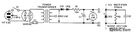
Provides revelse-voltage test of individual sections of rectifier stackat 1000 VDC,With test leads E1 and E2 clippedacross diode section under test,Variac setting is increased from 0 until C1 is charged to 1000 V as indicated by voltmeter. If diode or capacitor in section under test is defective, meter will read Iow because of extra voltage loss across R1 Initial setup is made with good diode section, Open S1 before changing diode because voltage is lethal.-R. K. Dye, Testing Dye-Odes, QST, Feb. 1976, p 44. (View)
View full Circuit Diagram | Comments | Reading(1106)
PORTABLE_TRANSISTOR_TESTER
Published:2009/7/11 4:22:00 Author:May
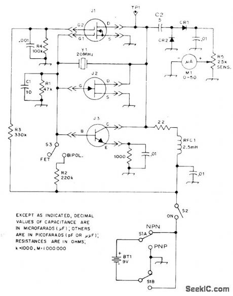
Go/no-go tester shows relative condition of NPN and PNP transistors, junction FETs, and dual-gate MOSFETs. Not suitable for checking audio or highpower RFtransistors. Crystal for upper range of HFspectrum is permanently wired; any HF crys-tal cut for fundamental-mode operation can be used. Rectified RF from oscillator is monitored on M1. S1 selects negative ground for testing N-ehdnnel FETs and NPN bipolars and provides positive ground for P-ehannel and PNP devices. If device is open, shomed, or extremely Ieaky, circuit wiII not oscillate and meter will not deflect. The higher the meter reading, the higher the gain of transistor at operating frequency. When testing MOSFETs that are not gate-protected, keep transistor Ieads shorted until device is in socket and replace short before re moving device. Diodes are 1N34A or equivalent.-D. DeMaw and C. Greene, A Pair of Handy Testers, QST, May 1973, p 24-27. (View)
View full Circuit Diagram | Comments | Reading(1413)
DIODE_TESTER
Published:2009/7/11 4:20:00 Author:May
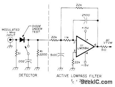
Developed to demonstrate how 0.002-μF shunt capacitor increases efficiency of diode detector. Can also be used to compare performance of different diodes, Input terminates AM signal generator. IC with associated capacitors and resistors forms low-pass filter having cutoff at 2 kHz. R1 is detector load. Resistor at output of U1 prevents oscillation of opamp when using coax feed to VTVM. For higher input signal levels, shunt capacitor in-creases AF output up to l0dB.-H. Olson, Diode Detectors, Ham Radio, Jan. 1976, p 28-34. (View)
View full Circuit Diagram | Comments | Reading(0)
IMPEDANCE_METER
Published:2009/7/11 4:19:00 Author:May
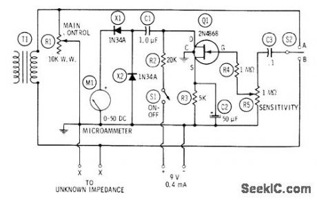
External AF voltage is applied to unknown impedance through input transformer T1 and calibrated variable resistor R1. Voltage drops across impedance and R1 are checked separately with electronic voltmeter while R1 is varied. When drops are equal, unknown impedance is equal to setting of R1, read directly from its calibrated dial. Voltmeter uses FET followed by two-diode rectifier X1-X2 and microammeter M1. With S2 in position A, volt-meter reads drop across R1 ; in position B, volt-meter reads drop across unknown impedance.Adjust R5 so meter deflection is near full scale to increase comparison accuracy. Common test frequencies used are 400, 500, and 1000 Hz.-R. P. Turner, FET Circuits, Howard W. Sams, Indianapolis, IN, 1977, 2nd Ed., p 143-144. (View)
View full Circuit Diagram | Comments | Reading(2122)
30_MHz_IF_AND_POWER_SUPPLY_FOR_10_GHz_GUNN_DIODE_COMMUNICATIONS_SYSTEMS
Published:2009/7/17 3:00:00 Author:Jessie
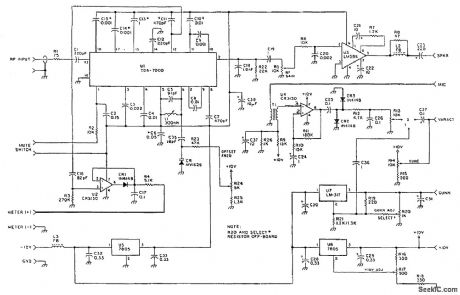
This unit consists of a TDA7000 IF amplifier and detector system,an LM386 audio amplifier,aCA3130 modulator circuit,a Gunn-diode supply( U7)that can be modulated with audio for production of wideband FM,and a 10-V regulator. (View)
View full Circuit Diagram | Comments | Reading(2199)
LOW_LEVEL_CURRENT_DETECTOR_AND_MEMORY
Published:2009/7/17 2:59:00 Author:Jessie
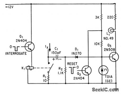
Unknown current Ix charges C1, 0percttion of relay K1 by interrogate pulse discharges C1 through tunnel diode, initiating switching of diode if in low-voltage state and unknown current is correct polarity. Lamp in transistor amplifier glows when tunnel diode is in high-voltage state. Currents of one picoampere can be measured.-C. D. Todd, Tunnel Diode Detects Currents Down to 100 Femtoamperes, Electronics, 36:14, p 33-37. (View)
View full Circuit Diagram | Comments | Reading(833)
DATA_ENTRY_KEYPAD_ENCODER
Published:2009/7/11 3:59:00 Author:May
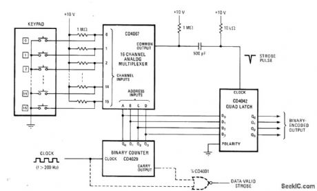
Designed for use in point-of-sale and other data-entry applications requiring bounceless binary encoder.Keypad is scanned by CD4067 16-channel analog multiplexer. When key is depressed, appropriate channel is driven low. When counter ad-dresses low input of multiplexer, common output goes low for one clock cycle. Differentiating network changes this to negative spike for strobing counter data into quad latch where it remains until another key is depressed clockshould be above 200 Hz.-M. E.κeppel, Multiplexer Scans Keyboard for Reliable Binary Encoding, Electronics, March 17,1977,p 99. (View)
View full Circuit Diagram | Comments | Reading(2929)
FET_TESTER
Published:2009/7/11 3:57:00 Author:May
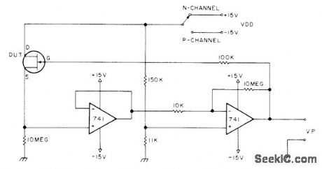
Can be used for measuring JFET pinchoff voltage, matching FETs of same ge-neric type, and measuring bias range of FET. Opamps sense source current of FET under test. First 741 is buffer, while second is preset to 1 V and its output used to drive device under test (DUT) until source current is 100 μA. Polarity of VP is opposite that of VDD.-Circuits, 73Mag-azine, June 1977, p 49. (View)
View full Circuit Diagram | Comments | Reading(7225)
NE602_INPUT_CIRCUITS
Published:2009/7/17 2:50:00 Author:Jessie
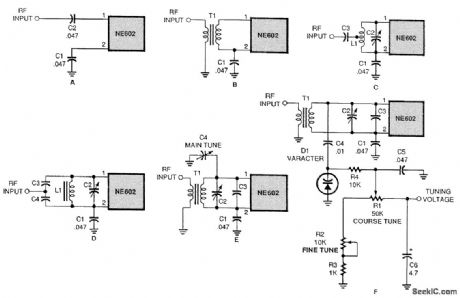
A few of the many ways to input a signal into the NE602. Simple untuned methods (a and b) are acceptable. If you need to tune to a specific frequency, you can use an LC resonant circuit with un-grounded trimmer capacitors (c and d) or with grounded variable capacitors (e). You can even use a tuning voltage in connection with a varactor (f). (View)
View full Circuit Diagram | Comments | Reading(0)
TRANSISTOR_AND_DIODE_TESTER
Published:2009/7/11 3:56:00 Author:May
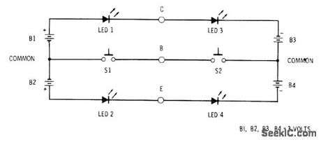
Four pairs of,AA penlight cells provide power for testing transistors and diodes quickly for opens and shorts. Circuit also distinguishes between PNP and NPN transistors and shows diode polarity. Leads of diode are inserted into base and collectoriacks (B and C), and switches are prqssed in succession. If LED 1 glows, diode is good and its anode lead is in collector jack. If LED 3 glows when S2 is pressed, anode of diode is in base jack. If both LEDs glow, diode is shorted. If neither LED glows, diode is open. With transistor in tester, unit is PNP if LED 1 and LED 2 glow. If LED 3 and LED 4 glow, unit is NPN. If one or no LEDs glow, transistor is open. If three or more LEDs glow, transistor has shorted junction. Any LEDs can be used.-F.M. Mims, Transistor Projects, Vol. 3, Radio Shack, Fort Worth, TX, 1975, p 87-93. (View)
View full Circuit Diagram | Comments | Reading(933)
1_kHz_TONE_DECODER
Published:2009/7/11 3:56:00 Author:May
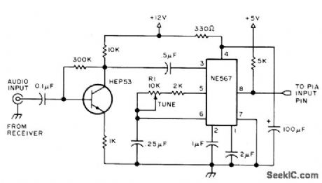
Used as interface between amateur CW receivel and Motolola 6800 microcomputer to copy any code speed from 3 to 60 WPM while adjusting automatically to irregularities of hand-sent code. Translation program given in article requires about 600 bytes of memory. Algorithm can be converted to run on almost any 8-bit microprocessor. Tone decoder is 567 phase-locked loop tuned to center frequency of about 1 kHz, with bandwidth of about 100 Hz. Circuitwill switch fast enough for most code speeds. PLL gives noise immunity.Optimum input level is about 200 mV. Output rests at +5 V dropping near ground when tone of correct frequency is detected.-R, D. Grappel and J. Hemenway, Add This 6800 MORSER to Your Amateur Radio Station, BYTE, Oct. 1976, p 30-35. (View)
View full Circuit Diagram | Comments | Reading(2297)
BROADBAND_NE602_INPUT_CIRCUITS
Published:2009/7/17 2:45:00 Author:Jessie
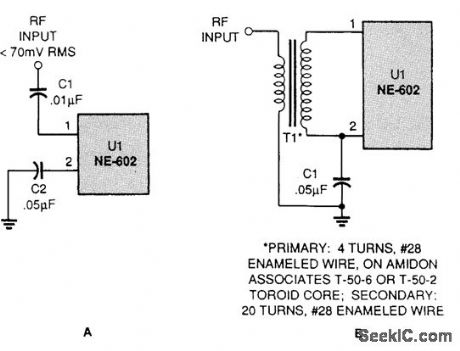
A variety of single-ended input circuits can be used with the NE602,including a broadband capacitor-coupled input and a broadband transformer-coupled input (View)
View full Circuit Diagram | Comments | Reading(833)
CRYSTAL_TESTER
Published:2009/7/11 3:46:00 Author:May
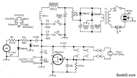
JFET Pierce oscillator will test any crystal from 50 kHz through 25-MHz upper frequency limit of fundamental-mode crystals without tuning, and drive counter for measuring crystal frequency, Will test overtone VHF crystals on their fundamental frequency. T1 is small output transformer from tube-type radio, having about 33: 1 turns ratio, or 6.3-V filament transformer if 1N645 rectifiers are used in place of 50-μF filter capacitors to give fullwave voltage doubler providing required 9 V. RFC1 is 2.5 mH, and RFC2 is 150-mH miniature toroid.-F. Brown, A Universal Crystal Oscillator, QST, Feb. 1978, p 15-16. (View)
View full Circuit Diagram | Comments | Reading(0)
POWER_SUPPLY_TESTER
Published:2009/7/11 3:45:00 Author:May
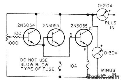
Serves as high-current solid-state-resistor load for testing power supplies before use, to determine voltage and current under load. Darlington configuration of transistors reduces power-dissipating requirements of pot. Use large heatsink for 2N3055s because they must dissipate almost 200 W when powersupply is delivering 15A at 15V.-E. Fruitman, The Smoke Tester, 73 Magazine, Nov, 1976, p 159. (View)
View full Circuit Diagram | Comments | Reading(3343)
INDUCTANCE_METER
Published:2009/7/11 3:43:00 Author:May
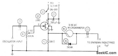
When used with variable-frequency audio oscillator, FET circuit checks any inductance between 60 μH and 60,000 H by resonance method. With unknown coil connected to terminals XX, external oscillator is tuned for peak deflection of M1. Inductance is then calculated from L=1/(395x10-9 f2) where L is in henrys and f is in hertz. if desired, calibration graph can be prepared to eliminate calculations. High input impedance of FET minimizes oscillatorloading. Ad just R1 forfull-scale deflection of meter at resonance, to give maximum sensitivity.-R. P. Turner, FET Circuits, Howard W. Sams, Indianapolis, IN, 1977, 2nd Ed., p 138-140. (View)
View full Circuit Diagram | Comments | Reading(1642)
CHRONOTRON_CIRCUIT_MEASURES_COAX_DELAY
Published:2009/7/17 2:40:00 Author:Jessie
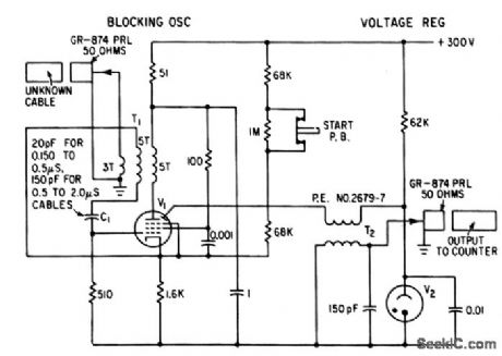
econdary-emission tube V1 (EPP-60) in blocking oscillator generates millimicrosec pulses that are fed to unknown cable through anode transformer. Pulse reflected back from open-circuited end of cable is coupled into grid through same transformer to initiate new pulse. Resulting pulse repetition rate, proportional to cable delay, is measured with 10.Mc digital counter-E. F. Laine, Getting Subnanosecond Precision in Coax Cable Delay Measurements, Electronics, 36:5, p 39-41. (View)
View full Circuit Diagram | Comments | Reading(851)
DENSIIOMETER
Published:2009/7/17 2:37:00 Author:Jessie

Used in scanning X-ray diffraction photograph and measuring densities of hundreds of spots. Circuit integrates point-by-point values of optical extinction over the required area of the negative.-E. M. Dooley, Flying-Spot Integrating Densitometer, Electronics, 34:3, p 64-66. (View)
View full Circuit Diagram | Comments | Reading(2188)
MULTIPLIER_SIMULATING_VOLTAGE_CONTROLLED_RESISTOR
Published:2009/7/17 2:33:00 Author:Jessie
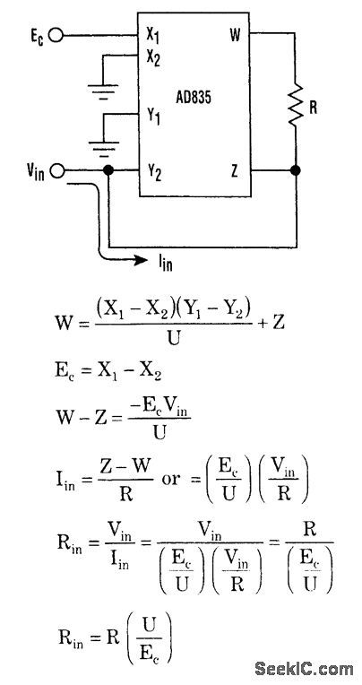
A two- or four-quadrant multiplier can be configured to simulate a resistor with a value that is the ratio of a fixed resistor and a control voltage. If the voltage-controlled current source is made to depend on input voltage Vin (i.e.by driving Y2), as well as being allowed to float on top of Vin(i.e. by connecting Y2 to Z), then the input of Y2 will simulate a resistor with the transfer function Rin= R(U/Ec). One node of the simulated resistor will always be referred to ground. (View)
View full Circuit Diagram | Comments | Reading(1001)
NANOAMPERE_SENSING_CIRCUIT
Published:2009/7/17 2:33:00 Author:Jessie
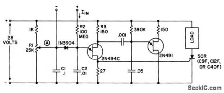
May be used as sensitive current detector or as voltage detector having high input impedance. Circuit input impedance is 100 meg. Input current of 40 nanoamperes charges C2 and raises emitter voltage of 2N494C to trig goring level. C1 and C2 then discharge, and resulting positive pulse triggers scr or other pulse-sensitive circuitry.-Transistor Manual, Seventh Edition, General Electric Co., 1964, p 326. (View)
View full Circuit Diagram | Comments | Reading(1281)
| Pages:42/101 At 204142434445464748495051525354555657585960Under 20 |
Circuit Categories
power supply circuit
Amplifier Circuit
Basic Circuit
LED and Light Circuit
Sensor Circuit
Signal Processing
Electrical Equipment Circuit
Control Circuit
Remote Control Circuit
A/D-D/A Converter Circuit
Audio Circuit
Measuring and Test Circuit
Communication Circuit
Computer-Related Circuit
555 Circuit
Automotive Circuit
Repairing Circuit