
Index 43
TRANSISTOR_TESTER
Published:2009/7/11 3:17:00 Author:May
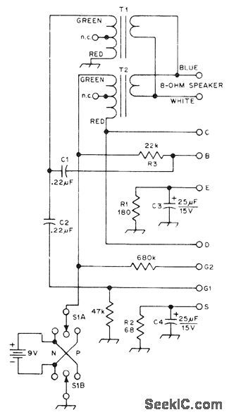
Will test conventional bipolar transistors, JFETs, MOSFETs, Darlingtons and UJTs. Audible note between 1000 and 5000 Hz from connected loudspeaker indicates that device is functioning as amplifier and gives relative indication of gain and noise figure. Most devices can be tested in-circuit. Among similar JFETs or MOSFETs, those producing lowest tone pitch have lowest noise figure. Among similar devices of any type, those producing loudest tone have highest gain. Tester feeds back audio signal through two transformers to create sustained oscillation when amplifying device is connected to proper terminals. S1 applies positive ornegative voltage through audio output transformer T2 to device under test. C3 and C4 must be nonpolarized electrolytics because R1 and R2 may produce either positive or negative voltage depending on device being tested. T1 and T2 have 1200-ohm primary and 8-ohm secondary (Calectro DI-724). Note above 10,000 Hz means device has some gain but does not meet specifications or is connected incorrectly. For MOSFETs, source and substrate are both connected to source terminal.-W. E. Anderson, A Universal Transistor Tester, QST, Dec. 1975, p 26-28. (View)
View full Circuit Diagram | Comments | Reading(0)
CLOCK_RING_COUNTER
Published:2009/7/11 3:11:00 Author:May

Switthing element is silicon controlled switch that approximates flip-flop, turning on when low-level positive pulse is applied to its base, and remaining on until turned off by negative pulse. Used us memory device to retain registered count until next input pulse makes bit transfer to following stage.-R.S. Reed, Rugged Arming Fuzing Timer for Atomic Artillery Missile, Electronics, 34:38, p48-51. (View)
View full Circuit Diagram | Comments | Reading(803)
BANDPASS_FILTER_TESTER
Published:2009/7/11 3:03:00 Author:May
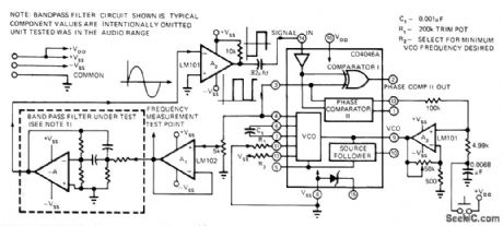
Measures center frequency of active bandpass filter by measuring phase angle as function of frequency. 0utput of VCO excites bandpass filter under test.Output of filter serves as input for PLL comparator. When VCO and filter signals are in phase, PLL Iocks at center frequency of filter, corresponding to 0°phase shift. Accuracy is 1% for measurements in AF range.-M. P. Prongue, Phase-Lock Loops Test Bandpass Filters, EDN Magazine, June 20, 1974, p 76 and 78. (View)
View full Circuit Diagram | Comments | Reading(1333)
TIL_TESTER
Published:2009/7/11 3:01:00 Author:May
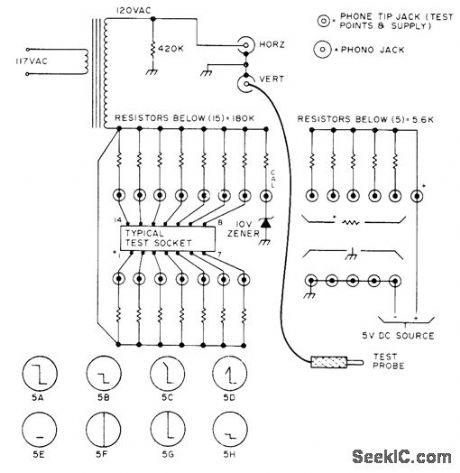
Used to check quality, identify intemal sections, and identify terminals of unmarked TTL ICs. Operates from 5-VDC source, which should have current-limhed output for fuse protection against shorts. Used with ordinary CRO, for which horizontal and vertical lacks are shown on diagram. Article tells how eight different oscilloscope displays are interpreted, and gives procedure for identifying terminals of chip one by one as test probe is held on pins.-S.S.Smith, Jr., A TTL Tester, 73 Magazine, Oct. 1976, p 110-111. (View)
View full Circuit Diagram | Comments | Reading(908)
POWER_PEAK_METER
Published:2009/7/11 3:00:00 Author:May
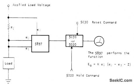
Optical Electronics 5897 four-quadrant multiplier generates product of load voltage and load current, while 5030 peak sense-and-hold module holds peak power for display on panel meter or other readout. Applications include measuring peak power applied to transistor, motor, lamp, or squib. If power peak at particular moment is required, such as that of transistor failure or squib detonation, 5020 sample-and-hold module is used in addition to or in place of 5030. Hold command can be obtained from flip-flop connected for triggering by abrup(change in power level.- A Peak Reading/Sampled Reading Power Meter, Optical Electronics, Tucson, AZ, Appli-cation Tip 10083. (View)
View full Circuit Diagram | Comments | Reading(784)
CODE_MONITOR
Published:2009/7/11 2:53:00 Author:May
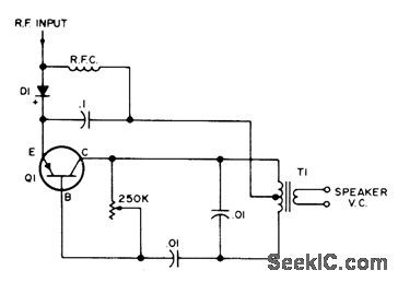
Works with any transmitter, regardless of type of keying. Use any good PNP transistor. With NPN transistor, reverse connections to diode. Frequency of tone gets higher as resistance of 250K pot is reduced.Monitor is turned off at minimum resistance.Enough RF to operate monitor can be obtained simply by connecting it to chassis of receiver or transmitter.-J. Smith, Yet Another Code Monitor, 73 Magazine, Sept. 1971, p 58. (View)
View full Circuit Diagram | Comments | Reading(859)
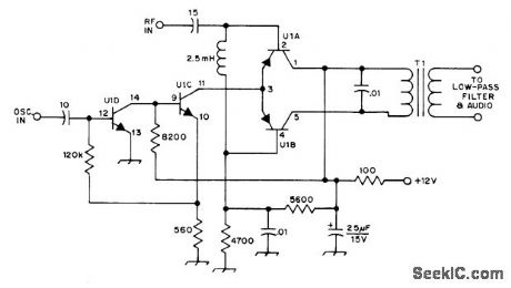
BFO_FOR_20_METERS
Published:2009/7/11 2:50:00 Author:May
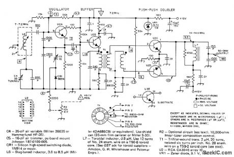
Uses CA3045 transistor array, with U2A as series-tuned Clapp oscillator covering 7-7.2 MHz. Tuned emitter-follower U2B provides push-pull drive at 7 MHz to bases of push-push doubler U2C-U2D. Output of BFO is applied to product detector rather than to mixer of receiver. Audio signal from detector is frequency difference between BFO and incoming signal, typically 700 Hz for CW reception.Article covers construction and adjustment.-D. DeMaw, Understanding Linear ICs, QST, Feb.1977, p 19-23. (View)
View full Circuit Diagram | Comments | Reading(1991)
TRANSISTOR_BREAKDOWN_TESTER
Published:2009/7/11 2:49:00 Author:May
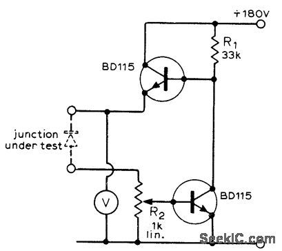
Simple circuit measures breakdown voltages of most types of small-signal and power transistors, reverse breakdown voltages of small power diodes, and zener diodevoltages. Two small 90V batteries in series provide power. R1 biases upper transistor into conduction. When voltage is applied to diode or transistor iunction under test, junction breaks down and current flows through R2. This makes lower transistor conduct, thereby dropping base voltage of upper transistor. R2 may be used to set breakdown current over wide range. Voltmeter reads breakdown voltage of junction, since drop across R2 is negligibly smalL-J. W. Brown, Simple Breakdown Voltage Meter, Wireless World, July 1973, p 337. (View)
View full Circuit Diagram | Comments | Reading(2292)
TONE_DECODER
Published:2009/7/11 2:49:00 Author:May

Decodes audio output of amateur radio receiver. Resulting audio tone burst corresponds to CW signal being received, with tone frequency varying with receiver tuning. Center frequency of NE567 phase-locked Ioop is ad justed with R1. Audio is translated into digital format of 1s and 0s, with tones for 0s. Output can be fed into computer for automatic translation of Morse code and printout as text,-W.A. Hickey, The Computer Versus Hand Sent Morse Code, BYTE, Oct. 1976, p 12-14 and 106. (View)
View full Circuit Diagram | Comments | Reading(0)
PORTABLE_CRYSTAL_TESTER
Published:2009/7/11 2:48:00 Author:May
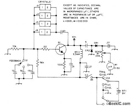
Pierce oscillatorusing 2N4124, MPS3563, or HEP53 NPN transistor gives indication of crystal activity on M1, from upper HF range down to at least 455 kHz. Increase feedback capacitance with S1 for lower frequency, Choose sockets J1-J4 for types of crystals to be tested. With known good crystal, circuit can also be used for checking bipolar transistors, with S3 providing correct polarity. Diodes are 1N34A germanium or equivalent.-D. DeMaw and C. Greene, A Pair of Handy Testers, QST, May 1973, p 24-27. (View)
View full Circuit Diagram | Comments | Reading(1730)
PRODUCT_DETECTOR
Published:2009/7/11 2:48:00 Author:May
Designed for use in 40-meter CW direct-conversion receiver, in which oscillator input is from 3.5-4 MHz VFO. U1 is RCA CA3046 transistor quad. Circuit provides bias stabilization for constant-current transistor and some amplification of AF output. T1 is audio transformer.-A. Pharos, The CA3046 IC in a Direct-Conversion Receiver, QST, Nov.1973,p 45. (View)
View full Circuit Diagram | Comments | Reading(0)
NTSC_RGB_VIDEO_DECODER
Published:2009/7/11 2:42:00 Author:May
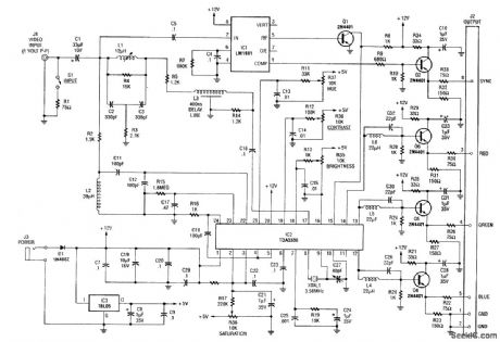
An NTSC/RGB decoder is shown here. Using a TDA3330, 1-V input video is broken down into its R, G, B components, and composite synch. U1 is an integrated synch separator (LM1881). This circuit should be useful for interfacing RGB monitors to NTSC video systems. (View)
View full Circuit Diagram | Comments | Reading(3887)
SIDETONE_MONITOR
Published:2009/7/11 2:38:00 Author:May
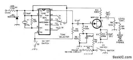
Mostek MK5086N IC is used with crystal in range from 2 to 3.5 MHz as signal generator driving FET audio amplifier.Switch S1 gives choice of four AF tones, determined by dividing crystal frequency in hertz by 5120 for T1, 4672 for T2, 4234 for T3, and 3776 for T4. Can also be used as code practice set and as audio signal generator.-J. Garrett, A Sidetone Monitor-Oscillator-Audio Generator, QST, June 1978, p 43. (View)
View full Circuit Diagram | Comments | Reading(1798)
IC_TEST_CLlP
Published:2009/7/11 2:28:00 Author:May
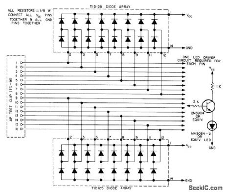
Provides in-circuit testing for all types of 16-pin ICs. LED array indicates logic status of each IC pin. Circuit uses Texas Instruments TID125 diode arrays on test clip to determine pin with highest voltage (VCC)and pin with lowest voltage (GND). These pins are then used to supply power to LEDs. No batteries are needed. Position of clip on IC is unimportant. On 14-pin ICs, disregard LEDs for two unused pins. Circuit can be expanded for 24- or 40-pin ICs, although adding LEDs makes clip more difficult to use.-J. Errico and R. Baker, Powerless IC Test Clip, BYTE, Dec. 1975, p 26-27. (View)
View full Circuit Diagram | Comments | Reading(2056)
TIMER_FOR_CODE_PRACTICE
Published:2009/7/11 2:21:00 Author:May
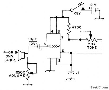
Signetics NE555V timer operating on 9-V supply serves as AF oscillator providing adequate volume for classroom instruction. Output tone can be varied from several hundred to several thousand hertz.-J. Bumey, Code Practice Oscillator, OST, July 1974, p 37. (View)
View full Circuit Diagram | Comments | Reading(1013)
AF_LINE_TESTER
Published:2009/7/11 2:04:00 Author:May
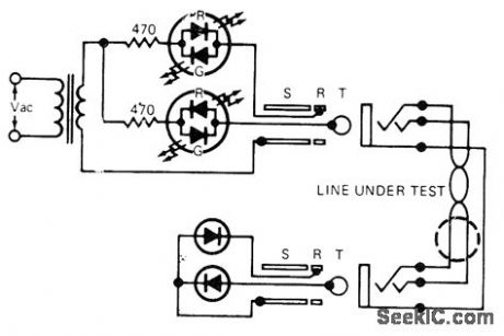
Gives complete check of shielded twisted-pair cablein one operation, indicating short-circuits between conductors and providing positive continuity check of each conductor. Tester using polarity-sensitive bicolor LEDs is connected to one end of cable under test, and two-diode plug is patched in at other end. If cable is good, only green LEDs come on. If a conductor in cable is open, oneor both green LEDs will be off. One or both red LEDs will light for short between any combination of conductors or if cable is wired incorrectly. Signal diode types are not criticaL-W. L. Mahood, Testerfor Balanced Audio Lines, EDN Magazine, April 5, 1974, p 80 and 82. (View)
View full Circuit Diagram | Comments | Reading(869)
FM_IF_STRIP
Published:2009/7/17 3:25:00 Author:Jessie
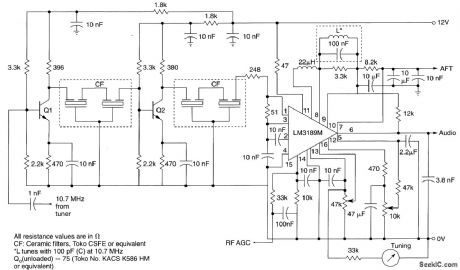
View full Circuit Diagram | Comments | Reading(805)
Digitally_programmable_limit_detector
Published:2009/7/17 3:16:00 Author:Jessie
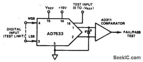
Digitally programmable limit detector(courtesy Analog Devices,Inc.). (View)
View full Circuit Diagram | Comments | Reading(678)
PROGRAMMABLE_IC_TESTER
Published:2009/7/11 1:57:00 Author:May
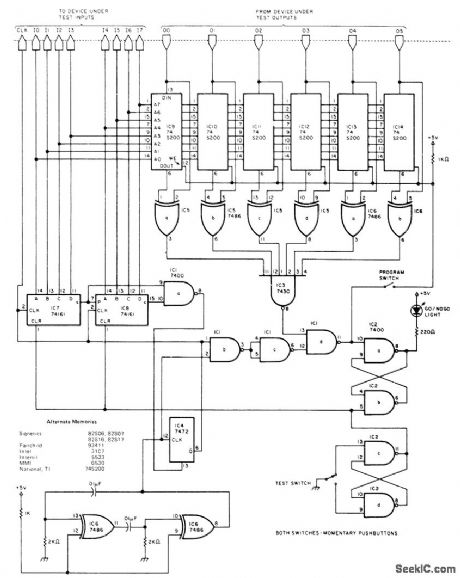
Provides automatic, instantaneous, and exhaustive tests of most small-scale integration gates, inverters, flip-flops, etc, and medium-scale integration counters, latches, shift registers, etc. Circuit sends eight lines of input data to device under test (DUT) and receives six lines of output. When TEST switch is closed, binary counter driving DUT input lines is cleared and flip-flop driving GO/NO-GO light is set. Upon release of switch, counter increments through all 256 input conditions. Between counts, data on output lines is compared with data stored in memories IC9-IC14. If mismatch exists, GO/NO-GO flip-flop is cleared at terminal count, CLEAR input of clock oscillator flip-flop is driven low, and further counts are inhibited until TEST button is pushed again. If GO/NO-GO light stays on, component passes test. To program, hold PROGRAM button down while testing known good device. Article gives examples of various applications.-M. Thorson, A. Programmable IC Tester, BYTE, June 1978, p 28, 30, 32, and 35. (View)
View full Circuit Diagram | Comments | Reading(2176)
SINGLE_OPAMP_TRANSISTOR_TESTER
Published:2009/7/11 1:54:00 Author:May
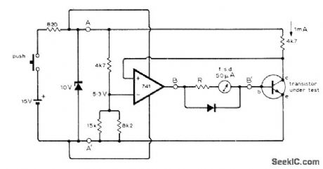
Meter scale is calibrated to read transistor gain directly for NPN devices. Addition of switch for reversing supply and meter polarities permits testing PNP devices as well. When reference voltage of 741 opamp is 5.3 V, circuit passes sufficient base current to make collector current 1 mA. Gain of transistor is then 1 mA divided by base current in microamperes; thus, 50-μA point on meter scale is marked for gain of 20 (1,000 divided by 50). Gain is 400 at 2.5 μA.-A. Rigby, Direet-Reading Transistor Tester, Wireless World, Aug. 1976, p 52. (View)
View full Circuit Diagram | Comments | Reading(1104)
| Pages:43/101 At 204142434445464748495051525354555657585960Under 20 |
Circuit Categories
power supply circuit
Amplifier Circuit
Basic Circuit
LED and Light Circuit
Sensor Circuit
Signal Processing
Electrical Equipment Circuit
Control Circuit
Remote Control Circuit
A/D-D/A Converter Circuit
Audio Circuit
Measuring and Test Circuit
Communication Circuit
Computer-Related Circuit
555 Circuit
Automotive Circuit
Repairing Circuit