
Index 56
NOISE_LIMITER
Published:2009/7/7 22:19:00 Author:May

This circuit is fed from the earphone jack of your receiver and goes to limiter control R6 and is then amplified by Q1: a common-emitter stage that has a voltage gain of only about 10, because of the negative feedback introduced by R3. The output of Q1 is fed to a simple clipping circuit, consisting of diodes Dl through D4. The diodes, connected in pairs, act like Zeners with an avalanche rating of about 1 V. The two pairs are connected opposite in polarity to each other, so that the audio signal is clipped at about 1 V. The signal is then coupled to the output socket through an emitter-follower buffer stage built around Q2 and an output attenuator control R7. (View)
View full Circuit Diagram | Comments | Reading(989)
TELEPHONE_SPEECH_ACTIVITY_DETECTOR
Published:2009/7/7 22:12:00 Author:May

This circuit can be used in telephone lines for speech activity detection purposes. This detection is very useful in the case of half-duplex conversation between two stations-in the case of simultaneous transmission of voice and data over the same pair of cables by the method of interspersion data on voice trafftc, and also in echo suppressor devices. The circuit consists of a class-A amplifier to amplify the weak analog signals (25-400 mV). The IC1 which follows, is connected as a retriggerable monostable multivibrator with the TR2 discharging the timing capacitor C3, if the pulse train reaches the trigger input 2 of IC1 with period less than the time: THIGH =1.1 R3C3. The output 3 of IC1 is active on when an analog or digital signal is presented at the output, and it drops to a low level, THIGH, seconds after the input signal has ceased to exist. (View)
View full Circuit Diagram | Comments | Reading(2089)
TELEPHONE_SOUND_LEVEL_METER_MONITOR
Published:2009/7/7 22:05:00 Author:May

The telephone-line decibel meter and line-voltage sensor shown lets you accurately monitor and adjust telephone sound levels. The 600-Ω resistor properly terminates the line. Power drain from the 9-V battery is 2 mA, and the meter provides ±30 dB range. (View)
View full Circuit Diagram | Comments | Reading(1408)
TELEPHONE_HANDSET_ENCODER
Published:2009/7/7 21:58:00 Author:May
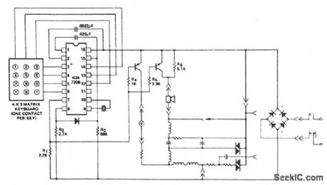
This encoder uses a single contact per key keyboard and provides all other switching functions electronically. The diode connected between terminals 8 and 15 prevents the output from goirfg more than 1 V negative with respect to the negative supply VSS. The circuit operates over the supply voltage range from 3.5 V to 15 V on the device side of the bridge rectifier. Transients as high as 100 V will not cause system failure, although the encoder will not operate correctly under these conditions. Correct operation will resume immediately after the transient is removed. The output voltage of the synthesized sine wave is almost directly proportional to the supply voltage (VDD - VSS) and will increase with the increase of supply voltage between terminals 8 and 16, after which the output voltage remains constant. (View)
View full Circuit Diagram | Comments | Reading(929)
OPTICALLY_INTERFACED_RING_DETECTOR
Published:2009/7/7 21:38:00 Author:May
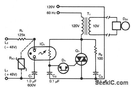
This ring detector, utilizing a neon-LDR (light-dependent resistor) optocoupler, simplifies interfacing with telephone lines. (View)
View full Circuit Diagram | Comments | Reading(828)
LIGHT_LEVEL_DETECTOR
Published:2009/7/7 21:22:00 Author:May
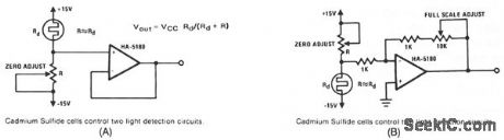
If R, the sensor matching resistor, is equal to the dark resistance of the cadmium sulfide cell, the amplifier output will range from 0 to≈ 2 as the light level ranges from dark to bright. The circuit in Fig. B operates similarly, but use the standard noninverting configuration instead of the voltage-follower configuration; this allows for variable gain. Although the dark resistance of the cadmium sulfide cell is only ≈7 KΩ, the principles of operation apply to other types of detectors which require the high-input impedance of the HA-5180 for reasonable linearity and useability. (View)
View full Circuit Diagram | Comments | Reading(739)
LOW_LIGHT_LEVEL_DROP_DETECTOR
Published:2009/7/7 21:15:00 Author:May
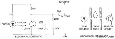
This self-biasing conftguration is useful any time small changes in light level must be detected, for example, when monitoring very low f1ow rates by counting drops of fluid. In this bias method, the photodarlington is dc bias stabilized by feedback from the collector, compensating for different photodarlington gains and LED outputs. The 10-μF capacitor integrates the collector voltage feedback, and the 10-MΩ resistor provides a high base-source impedance to minimize effects on optical performance. The detector drop causes a momentary decrease in light reaching the chip, which causes collector voltage to momentarily rise, generating an output signal. The initial light bias is small because of output power constraints on the LED and mechanical spacing system constraints. The change in light level is a fraction of this initial bias because of stray light paths and drop translucence. The high sensitivity of the photodarlington allows acceptable output signal levels when biased in this manner. This compares with unacceptable signal levels and bias point stability when biased conventionally, i.e., base open and signal output across the collector bias resistor.
(View)
View full Circuit Diagram | Comments | Reading(1099)
BATTERY_CAPACITY_TESTER
Published:2009/7/7 20:20:00 Author:May

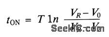
The test circuit gives an indication of the capacity remaining in a battery. By noting the time in seconds that the LED remains on after you depress the test switch S1. The circuit has proven reliable in testing NiCad-, carbon-, and alkaline-type batteries. Closing S1 activates the circuit by applying voltage from the battery under test. Voltage V1 jumps to a value V0= VRR3/(R2 + R3) when the switch closes and then increases with a time constant T = C1 (R2 + R3). The divider R4/R5 fixes V2. The reference circuit IC1 sets VR to approximately 2.5 V. The op amp's output remains high (LED on) until V1 rises to the level of V2, when the LED turns off. Calculate the on-time tON as follows:
(View)
View full Circuit Diagram | Comments | Reading(1113)
SOUND_CTIVATED_DECODER
Published:2009/7/7 8:40:00 Author:May
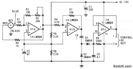
The piezo transducer operates as a sound-pickup device as well as a frequency-selective filter. By controlling the gain of the op amps, the oscillator can be transformed into a sensitive and frequency-selec-tive tone-decoder circuit. With the gain of U1a set just below the point of self oscillation, the transducer becomes sensitive to acoustically coupled audio tones that occur at or near its resonant frequency.
The circuit's output can be used to activate optocouplers, drive relay circuits, or to control almost any dc-operated circuit. The dc signal at the output of U1c varies with 0 to over 6 V, depending on the input-signal level. One unusual application for the sound-activated decoder would be in extremely high-noise environments, where normal broadband microphone pickup would be useless. Because piezo transducers respond only to frequencies within a very narrow bandwidth, little if any of the noise would get through the transducer. (View)
View full Circuit Diagram | Comments | Reading(1282)
DIRECTION_DETECTOR_DECODER
Published:2009/7/7 8:37:00 Author:May
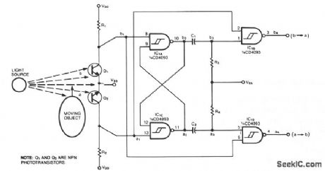
This circuit, which was developed to monitor the traffic of bumblebees in and out of the hive, differentiates a-to-b motion from b-to-b motion. When used with an optical decoder, the circuit distinguishes clockwise from counterclockwise rotation and provides a resolution of one output pulse per quadrature cycle.
Q1 and Q2 are mounted so that a moving object first blocks one phototransistor, then both, then the other. Depending on the direction in which the object is moving, either IC1B or IC1D emits a negative pulse when the moving object blocks the second sensor. An object can get as far as condition 3 and retreat without producing an output pulse; that is, the circuit ignores any probing or jittery motion. If an object gets as far as condition 4, however, a retreat will produce an opposite-direction pulse.
The time constants R3C1 and R4C2 set the output pulse width. A 100 K Ω/100pF combination, for example, produces 10-μs pulses. Select a value for pullup resistors R1 and R2 from the 10 K to 100 KΩ range, according to the sensitivity your application requires. (View)
View full Circuit Diagram | Comments | Reading(2000)
ENCODER_DECODER
Published:2009/7/7 8:36:00 Author:May
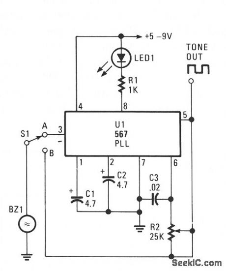
The transducer circuit can be operated as either a tone encoder or decoder by changing the position of S1. The operating frequency of that dual-purpose circuit is determined by C3 and R2.Capacitors C1 and C2 are not critical and can be of almost any value between 1 and 5 mf. When the circuit is receiving an on-frequency signal, LED1 lights. Although a two wire piezo transducer with a resonance frequency of 2500 Hz was used in the circuit, any piezo unit should work-as long as the values of C3 and R2 are selected to tune to the transducer's operating frequency.
With power on and S1 in the B position, adjust R2 for the loudest tone output. The circuit should be tuned to the resonance frequency of the trans-ducer. In that position, the circuit can be used as an acoustical or tone signal encoder. Next, switch to the A position and aim an on-frequency audible tone toward the transducer; the LED should light, indicating a decoded signal. (View)
View full Circuit Diagram | Comments | Reading(988)
INFRARED_TRANSMITTER_1
Published:2009/7/7 8:31:00 Author:May

View full Circuit Diagram | Comments | Reading(1781)
SIMPLE_IR_DETECTOR
Published:2009/7/7 8:29:00 Author:May
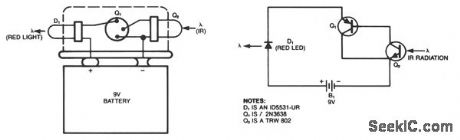
This simple IR detector turns on a real LED when Q2 is exposed to invisible IR radiation found in fiber-optics systems, position sensors, and TV remote-control units. The device can be built on top of a 9-V battery and held in place with RTV. Its power dissipation is virtually zero, unless IR radiation or high ambient light is present. Normal fluorescent lighting is not a problem, but if necessary add an IR filter to the Q2 detector to exclude ambient light. Exposing the detector to a strong light or IR source gives a quick check of the battery and the red LED. (View)
View full Circuit Diagram | Comments | Reading(0)
LONG_RANGE_OBJECT_DETECTOR
Published:2009/7/7 8:20:00 Author:May

When long ranges must be worked with IR light sources, and when high system reliability is required, pulsed-mode operation of the IR is required. Additional reliability of operation is attained by synchronously detecting the photodetector current, as this circuit does. PC-1 is an IR and phototransistor pair which detect the presence of an object blocking the transmission of light from the IR to the phototransistor. Rela-tively long-distance transmission is obtained by pulsing the IR, with about 10-pts pulses, at a 2-ms period, to 350 mA via the 2N6027 oscillator. The phototransistor current is amplified by the 2N5249 and 2N5356 amplifier to further increase distance and allows use of the H11A5, also pulsed by the 2N6027, as a syn-chronous detector, providing a fail-safe, noise immune signal to the 2N5249 pair forming a Schmitt-trigger output.This design was built for battery operation, with long battery life a primary consideration. Note that another stage of amplification driving the IR can boost the range limited by the IR VF, by 5 to 10 times. A higher supply voltage for the IR can double this range.Today, optoelectronics are mostly used to transmit electronic information over light beams. These applications range from the use of optocouplers transmitting information between IC logic circuits and power circuits, between power lines and signal circuits, between telephone lines and control circuitry, to the pulse-modulated systems which transmit information through air or fiber optics over relatively great distances. (View)
View full Circuit Diagram | Comments | Reading(1096)
TONE_DECODER
Published:2009/7/7 8:10:00 Author:May
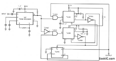
Adding a pair of one shots to the output of a 567 tone decoder renders it less sensitive to out-of-band signals and noise. Without the one shots, the 567 is prone to spurious output chatter. Other protection schemes, such as feeding back outputs or using an input filter, do not work as well as the one shots. The output of the 567 is high in the absence of a tone and becomes low when it detects a tone. The tone decoder triggers a one shot via an AND gate. The one shot's period is set to slightly less than the duration of a tone burst.
When the output of the tone decoder decreases, it triggers the second one shot. The second one shot's period is set to slightly less than the interval between tone bursts. The flip-flop enables and disables the inputs to one shots so that spurious outputs from the tone decoder do not affect the output.
(View)
View full Circuit Diagram | Comments | Reading(0)
CURRENT_MONITOR
Published:2009/7/7 7:23:00 Author:May
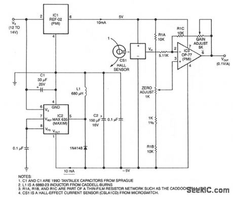
This circuit uses a Hall-effect sensor, consisting of an IC that resides in a small gap in a flux-collector torrid, to measure dc current in the range of 0 to 40 A. You wrap the current-carrying wire through the toroid; the Hall voltageVH is then linearly proportional to current I. The current drain from VB is less than 30 mA.To monitor an automobile alternator's output current, for example, connect the car battery between the circuit's VB terminal and ground, and wrap one turn of wire through the toroid. Or, you could wrap 10 turns-if they fit-to measure 1 A full scale. When I = 0 V current sensor CSI'sVH output equals one-half of its 10 V bias voltage. Because regulators IC1 and IC2 provide a bipolar bias voltage,VH and VOUT are zero when I is zero; you can then adjust the output gain and offset to scaleVOUT at 1 V per 10 A. (View)
View full Circuit Diagram | Comments | Reading(0)
SMOKE_DETECTOR_2
Published:2009/7/7 7:18:00 Author:May
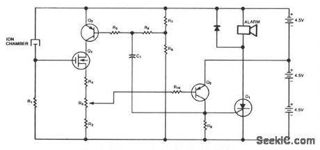
This circuit comes from U.S. Patent 3,778,800, granted to BRK Electronics in Aurora, IL. The circuit provides a smoke detector with an alarm for both smoke and low batteries. The R6/R7 voltage divider monitors the battery and will turn Q2 and Q1 off when the battery voltage falls too low. The smoke-detec-tor chamber will also cut Q1 off when it senses smoke. Q1 via Q3, triggers SCR Dl and sounds the alarm. Capacitor C1 provides feedback that causes the alarm to sound intermittently. The smoke detector and low-battery circuits sound the alarm at two different rates. (View)
View full Circuit Diagram | Comments | Reading(907)
GAS_SMOKE_DETECTOR
Published:2009/7/7 7:17:00 Author:May

In the presence of smoke or gas, the ac output voltage increases and becomes rectified, filtered and zener-diode coupled (D2 for thresholding) to sensitivity control R3. Under no gas condition, the output equals approximately 0 V (high). When gas is present, the output will be a negative value (low) sufficient to overcome the threshold of McMOS gate 2 and D2. The circuit shown uses a TGS 308 sensor, a general-purpose gas detector that is not sensitive to smoke or carbon monoxide. If smoke is the primary element to be detected, use the TGS 202 sensor. The two sensors are basically identical; the main differences lie in the heater voltage and the required warm up time delay. The TGS requires a 1.2 V heater and a 2 minute delay, whereas the TGS 202 requires 1.5 V and 5 minutes, respectively.The system uses a McMOS gated oscillator directly interfacing with a triac-controlled ac horn. Using the MC14572 HEX functional gate, four inverters, one two-input NAND gate and one two-input NOR gate, the circuit provides the complete gas/smoke detector logic functions time delay, gated astable multi-vibrator control and buffers operation. The 24-Vac ham produces an 85/90-dB sound level output at a dis-tance of 10 ft. Controlled by the astable multivibrator, the ham generates a pulsating alarm-a signal that may be advantageous over a continuous one in some noise environments. (View)
View full Circuit Diagram | Comments | Reading(1275)
SMOKE_DETECTOR_1
Published:2009/7/7 7:15:00 Author:May

This smoke detector uses a MEM 817 p-channel enhancement mode MOSFET as its buffer amplifier. Operation of the sensor is based on a decrease in the current when smoke enters the chamber, thereby causing a negative voltage excursion at the gate of the buffer MOSFET. Quiescent voltage values at the output of the chamber vary from about -4 V to -6 V, and detection of smoke will result in an excursion of about -4 V. The MOSFET is connected as a source follower. (View)
View full Circuit Diagram | Comments | Reading(796)
GAS_SMOLE_DETECTOR
Published:2009/7/7 7:10:00 Author:May
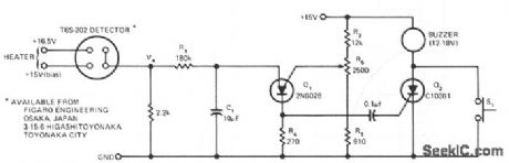
The sensor is based on the selective absorption of hydrocarbons by an n-type metal-oxide surface. The heater in the device serves to burn off the hydrocarbons once smoke or gas is no longer present in the immediate area; hence, the device is reuseable. When initially turned on, a 15 minute warm-up period is required to reach equilibrium (VA ≌ 0.6 V) in a hydrocarbon-free environment. When gas or smoke is introduced near the sensor, VA will quickly rise (rate and fmal equilibrium depend on the type of gas and concentration) and trigger Q1, a programmable unijunction transistor. The voltage pulse generated across R4 triggers Q2, sounding the buzzer until S1 resets the unit. R1 and C1 give a tiine delay to prevent small transient waves of smoke, such as from a cigarette, from triggering the alarm. Triggering threshold is set by R5, R2, and R3; with the components shown, between 50 and 200 ppm of hydrocarbons can be easily detected. Since it is somewhat sensitive to heater voltage, a regulated supply should be used. Power requirements are 1.5 V at 500 mA for the heater and 15 V at 30 mA, depending on type of buzzer, for the bias supply. (View)
View full Circuit Diagram | Comments | Reading(826)
| Pages:56/101 At 204142434445464748495051525354555657585960Under 20 |
Circuit Categories
power supply circuit
Amplifier Circuit
Basic Circuit
LED and Light Circuit
Sensor Circuit
Signal Processing
Electrical Equipment Circuit
Control Circuit
Remote Control Circuit
A/D-D/A Converter Circuit
Audio Circuit
Measuring and Test Circuit
Communication Circuit
Computer-Related Circuit
555 Circuit
Automotive Circuit
Repairing Circuit