
Index 54
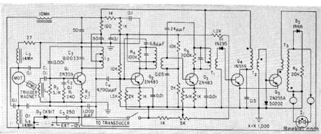
METAL_DETECTOR
Published:2009/7/8 21:51:00 Author:May

Will detect small coin up to about 5 inches underground and larger metal objects at much greater depths. Frequency of search oscillator Tr1- Tr2 depends on values used for three paralleled capacitors, search coil, and metal obiects in vicinity of coil. Mixer Tr3 feeds difference between search oscillator and reference oscillator Tr4-Tr5 to opamp and Tr6 for driving phones or loudspeaker. Article gives construction and adjustment details, including dimensions for search coil. Reference oscillator is set to 625 kHz. C1 is 560 pF, C2 150 pF, and C3 10 pF variable. C2 is used for coarse tuning, and C3 for fine ad justment to get beat note. Diodes are 1N4148. Tr3 is BC308, BCY72, or equivalent, and other transistors are BF238 BC108, or equivalent.-D. E, Waddington, Metal Detector, Wireless World, April 1977, p 45-48. (View)
View full Circuit Diagram | Comments | Reading(0)
TWIN_OSCILLATOR_METAL_DETECTOR
Published:2009/7/8 21:21:00 Author:May
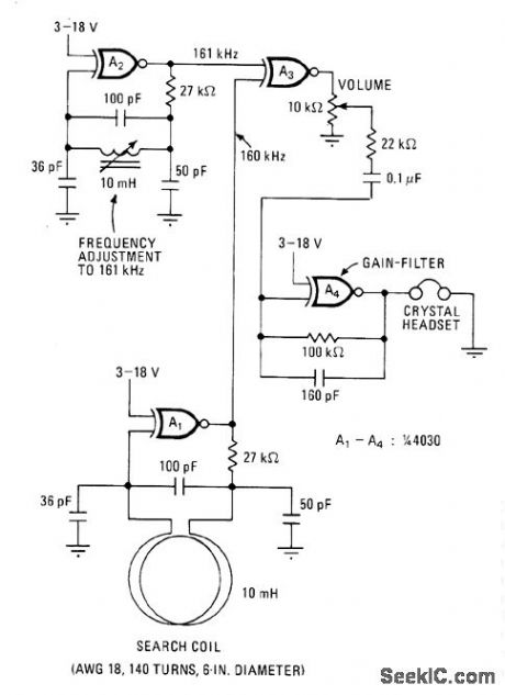
Metal object near search coil changes frequency of oscillator A1 which is initially tuned to 160 kHz,thereby changing frequency of 1-kHz output derived by mixing with 161-kHz output of A2. Sensitivity, determined largely by dimensions of search coil, is sufficient to detect coins about 1 foot away.-M. E. Anglin, C-MOS Twin Oscillator Forms Micropower Metal Detector, Electronics, Dec. 22, 1977, p 78. (View)
View full Circuit Diagram | Comments | Reading(1285)
PORTABLE_FISH_FINDER
Published:2009/7/23 22:59:00 Author:Jessie


Measures depth up to 120 feet and provides lower-intensity echoes from schools of fish. Indicator is neon lamp at end of rotating arm driven by constant-speed motor. Magnet triggers 200-kc ultrasonic transmitter and makes neon lamp glow of zero on circular scale. Lamp glows again for each echo pulse from fish and for bottom echo.-H. C. Single, Portable Depth Finder for Small Boots, Electronics, 33:6, p 50-51. (View)
View full Circuit Diagram | Comments | Reading(3287)
01℃_PRECISION
Published:2009/7/8 5:32:00 Author:May
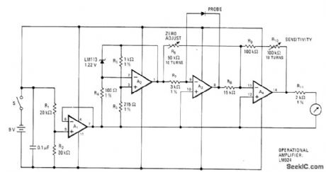
Temperature sensor is LM113 diode in probe, with sections A1 and A2 of LM324 quad opamp maintaining constant current to diode to ensure that voltage changes across diode are direct result of temperature.4.5-V output of A1 is reference point for other opamps. Changes in output voltage of diodeare reflected in output of A4 through buffer A3. Calibration involves adjusting R6 for zero output voltage at low end of temperature range,then adjusting R10 for full-scale or other convenient reading at desired upper temperature limit. Use 1-mA meter movement.-Y. Nezer, Accurate Thermometer Uses Single Quad Op Amp, Electronics, May 26, 1977, p 126. (View)
View full Circuit Diagram | Comments | Reading(2040)
PROXIMITY_DETECTOR
Published:2009/7/8 5:28:00 Author:May
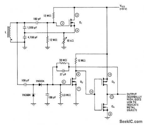
Output changes from high (9 V) to low (0 V) when conducting object moves within1cm from open end of 150-turn coil L (No.34 enamel) mounted in half of Fer-roxcube 1811-PL00-3B7 core set. Can be used as contactless limit switch or tachometer pickup.Q1-Q 4are CM0S MOSFETs in CD4007A package.Q1 and pickup coil form 100-kHz oscillator Diodes develop DC voltage proportional to peak-to-peak value of oscillator signal, for application to Schmitt trigger Q2-Q4. Conductive object near coil absorbs energy from magnetic field, lowering oscillator amplitude and turning Schmitt trigger off. 10K pot adjusts sensitivity.Circuit drives CM0S logic directly. For TTL drive, use buffer.-M. L. Fichtenbaum, Inductive Proximity Detector Uses Little Power, Electronics, Jan. 22, 1976, p 112. (View)
View full Circuit Diagram | Comments | Reading(0)
START_AND_RUN_MOTOR_CIRCUIT
Published:2009/7/8 4:52:00 Author:May
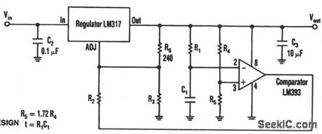
The timed two-voltage circuit can start and run a small dc motoror solenoid.The input voltage to the LM317 three-terminal regulator ranges from 5 to 40 V, and the output voltage can range from 2 to 36 V With input voltage VIN initially applied to the input,and capacitor C1 in a discharged state,the LM393 comparator's open-collector output circuit is open-circuited,Then the higher start-up output voltage is:
VOUT=1.25[1+(R3/240)]
At a time t after start-up,when:
t=-R1C1Ln[R4/(R4+R5)]or:
t=-R1C1,if R5=1.72R4
the comparator output decreases.At that time,the output voltage switches to a lower value to run thedevice at its proper operating level. (View)
View full Circuit Diagram | Comments | Reading(801)
RED_GREEN_LED_MONITOR
Published:2009/7/8 5:02:00 Author:May
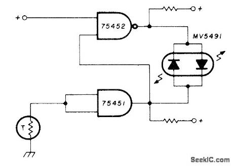
Set points are adjusted by trimming resistor shunted across thermistor, to give onecolor when desired temperature has been reached and other color when temperature is low. Uses Monsanto MV5491 dual red/green LED, with 220 ohms in upper lead to +5 V supply and 100 ohms in Iower +5 V Iead because red and green LEDs in parallel back-to-back have different voltage rea quirements. LED drivers are SN75452 and SN75451.-K. Powell, Novel Indicator Circuit, Ham Radio, April1977, p 60-63. (View)
View full Circuit Diagram | Comments | Reading(832)
MODULATION_MONITOR
Published:2009/7/8 4:37:00 Author:May
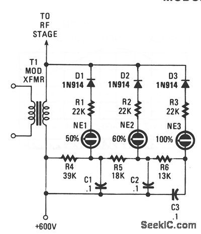
Switching diodes are used to fire the neon lamps when negative-peak modulation hits 50, 60, and 100%. To use the circuit, keep an eye on the lamps. You should attempt to keep the 50% lamp firing all the time, the 60% lamp should be on as much as possible, but try to prevent the 100% lamp from lighting. (View)
View full Circuit Diagram | Comments | Reading(0)
_BUG_DETECTOR
Published:2009/7/8 4:23:00 Author:May
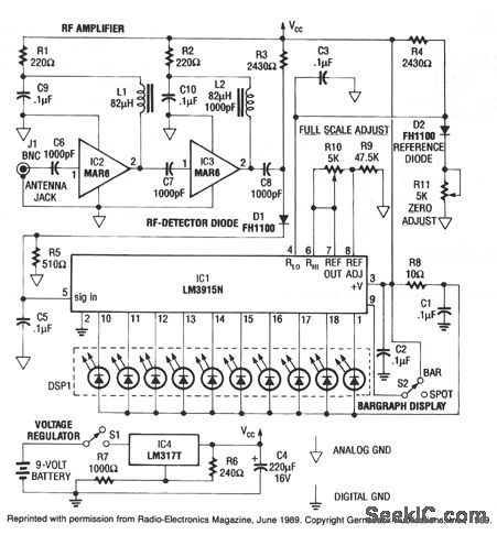
This rf detector can locate low-power transmitters (bugs) that are hidden from sight. It can sense the presence of a 1-mW transmitter at 20 feet, which is sensitive enough to detect the tiniest bug. As you bring the rf detector closer to the bug, more and more segments of its LED bar-graph display light, which aids in direction finding.
The front end has a two-stage wideband rf amplifier, and a forward-biased hot-carrier diode for a detector. After detection, the signal is filtered and fed to IC1, an LM3915N bar-graph driver having a logarithmic output. Each successive LED segment represents a 3-dB step. (View)
View full Circuit Diagram | Comments | Reading(2837)
AIR_MOTION_DETECTOR
Published:2009/7/8 4:21:00 Author:May
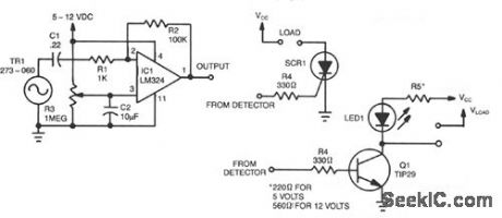
When a current of air hits the piezo element, a small signal is generated and is fed through C1 and R1 to inverting input pin 2 of one section of the LM324. That causes output pin 1 to increase. Resistor R3 is used to adjust the sensitivity of the detector. The circuit can be set so high as to detect the vnvy of a hand or so low that blowing on the element as hard as you can will produce no output. Resistor R2 is used to adjust the level of the output voltage at pin 1.
The detector circuit can be used in various control applications. For example, an SCR can be used to control 117-Vac loads as shown. Also, an npn transistor, such as a TIP29, can be used to control loads as
(View)
View full Circuit Diagram | Comments | Reading(0)
80_W_ON_2_METERS
Published:2009/7/8 4:20:00 Author:May
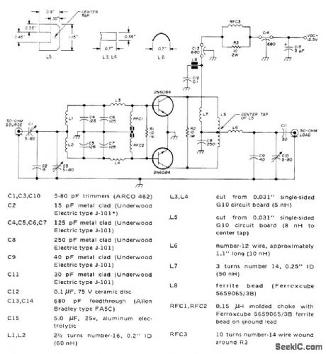
Single-stage design using two 2N6084 transistors combined with simple LC components can be tuned from 144 to 175 MHz. Typical input is 20W for 80-W output at 144 MHz. Article shows how to add 2N6083 driver stage that reduces input drive require-ment to 2,5 W. Power gain at 144 MHz is 6 dB. Article covers construction and adjustment.—J. Hatchett, A Solid 80 Watts fol Two Meters, Ham Radio, Dec. 1973, p 6-12. (View)
View full Circuit Diagram | Comments | Reading(3541)
BREATH_ALERT_ALCOHOL_TESTER
Published:2009/7/8 4:07:00 Author:May
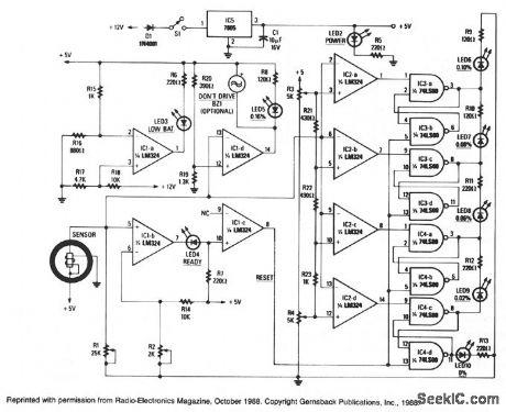
When power is applied to the circuit, the heater coil in the sensor is energized by the 5-V output of IC5, a 7805 voltage regulator. Breathing into the sensor with alcohol on your breath will lower the sensor's resistance; consequently, the input voltage to the detector circuit, will change. The detector circuit consists of quad op amp, IC2 and its associated circuitry. All sections of the detector circuit are calibrated via R3 and R4, and the inputs to each section are controlled by the voltage-divider network R21 through R23.As each section is triggered, the outputs decrease, and sample-and-hold circuits, IC3 and IC4, will latch onto the highest input value and drive the appropriate LED. The different colored LEDs represent alcohol levels front 0 to 0.16%.
If the level of alcohol is above the legal limit, or 0.16%, part of another quad op amp, IC1d, will turn on both the optional buzzer and LED5. That is an indication of a high level of alcohol present in your blood, and you definitely should not drive.
After a test is taken,the sensor takes a few seconds to ready itself for another test. When the sensor is ready, its input to IC1b, adjusted via R2 to a threshold of 0.5 V, causes LED4 (ready) to light. That, in turn, causes IC1c to reset the rest of the circuitry. The last section of IC1 is biased via R15 and R16, and used to indicate a low-battery condition-when the battery voltage drops below 6.8 V-which could result in an inaccurate breath test. (View)
View full Circuit Diagram | Comments | Reading(2949)
455_kHz_WITH_PRODUCT_DETECTOR
Published:2009/7/8 3:50:00 Author:May
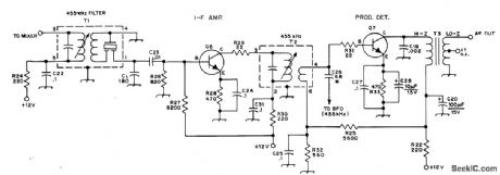
Bipolar transistor Q6 provides about 20-dB gain at 455 kHz, which is adequate for handling wide range of signal amplitudes without changing audio gain setting in receiver without AGC. Product detector produces output in audio range when its inputs are 455-kHz IF signal and BF0 signal near 455 kHz. Transistors can be 2N222, 2N3641, 2N4123, or equivalent. T1 is J. W. Miller 8814 455-kHz IF transformer/filter, T2 is miniature 455-kHz lF transformer, and T3 is miniature audiotransformer with 10K primary and 2K center-tap secondary (CT not used).-D. DeMaw and L. McCoy, Leaming to Work with Semiconductors, QST, Aug. 1974, p 26-30. (View)
View full Circuit Diagram | Comments | Reading(4031)
TEMPERATURE_DIFFERENCE_DETECTOR
Published:2009/7/8 3:14:00 Author:May
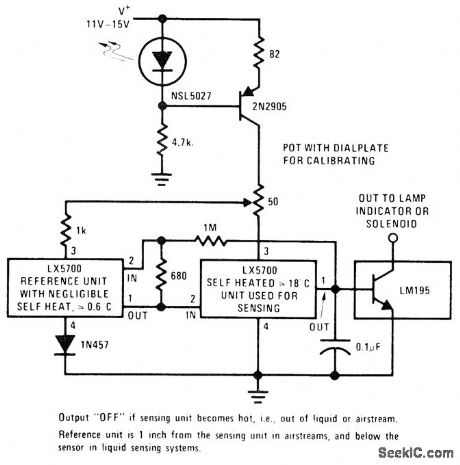
Pair of National LX5700 temperature transducers delivers output voltage proportional to temperature difference between transducers, as required for sensing temperature gradient in chemieal processes, detecting failure of cooling fan, detecting movement of cooling oil, and monitoring other heat-absorbing phenomena.With sensing transducer in hot condition (out of liquid or in still air for 2 min), adjust 50-ohm pot to setting that just turnspower output off. Next, with transducer in cool condition (in liquid or in moving air for 30 s), find setting that just tums output on. These settings overlap, but final setting between them will provide stable operation.-P. Lefferts, A New Interfacing Concept; the Monolithic Temperature Transducer, National Semiconductor, Santa Clara, CA, 1975, AN-132, p 7.
(View)
View full Circuit Diagram | Comments | Reading(1245)
THREE_MINUTE_TIMER
Published:2009/7/8 3:02:00 Author:May
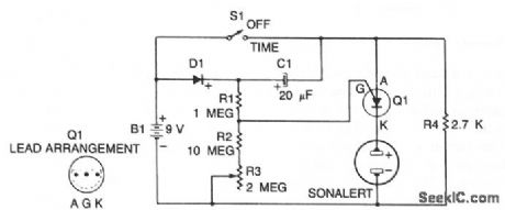
When S1 is off, C1 charges to within 0.5 V of the battery voltage through diode D1 and resistor R4. When S1 is closed, the anode of the PUT rises to the positive supply voltage. The PUT does not conduct, because battery voltage appears in series with the charge stored on C1, which raises the gate of the PUT to a level positive with respect to the anode. The timer relies on the discharge of capacitor C1 through resistors R1, R2, R3,and R4. Once C1 is at zero volts, the PUT will turn on battery voltage to the Sonalert and cause it to sound. (View)
View full Circuit Diagram | Comments | Reading(858)
COUPLING_TO_HIGH_IMPEDANCE_DETECTOR
Published:2009/7/8 2:58:00 Author:May
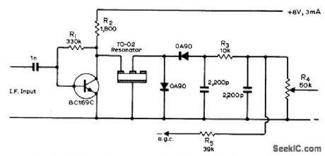
Final IF stage of receiver uses piezoelectric overtone resonator connected backwards for coupling to high-impedance detector. Arrangement provides useful voltage step-up as well, about 2.5 times. Resonator can be Brush Clevite Transfilter.-G. W. Short, Reversed Operation of Transfilter,' Wireless World, Aug. 1971, p 386. (View)
View full Circuit Diagram | Comments | Reading(639)
LONG_TIME_TIMER
Published:2009/7/8 2:49:00 Author:May
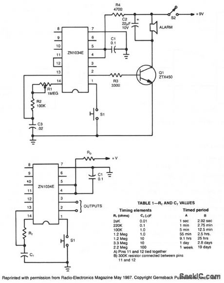
When used as a stand-alone device, ZN1034E from Ferranti can provide timed intervals ranging from 1 second to 19 days, although the rc time constant is only 220 seconds. The ZN1034E includes an internal voltage regulator, an oscillator, and a 12-stage binary counter. The total delay time prodded by the counter is 4095 times the oscillator period. The control logic times-out after 4095 cycles of the oscillator, and delivers high and low output pulses at pins 2 and 3. The output at pin 3 is normally high and decreases at the end of the timed interval. The complementary output at pin 2 is normally low and becomes high at the end of the timed interval. The timing period is initiated by momentarily grounding pin 1. Timing resistor RT consists of two resistors, R1 and R2, in series. Because R1 has a fixed value of 100 KO, the total range of ;RT 100 K to 1.1 MΩ. (View)
View full Circuit Diagram | Comments | Reading(1755)
CMOS_PRECISION_PROGRAMMABLE_LABORATORY_TIMER
Published:2009/7/8 2:38:00 Author:May
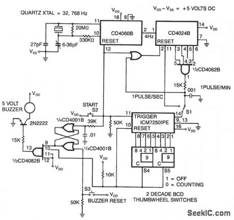
The time base is ftrst selected with S1 set for seconds or minutes, then units 0-99 are selected on the two thumbwheel switches S4 and S5. Finally, switch S2 is depressed to start the timer. Simultaneously, the quartz crystal-controlled divider circuits are reset, the ICM7250 is triggered and counting begins. The ICM7250 counts until the preprogrammed value is reached, then, the value is reset, pin 10 of the CD4082B is enabled, and the buzzer is turned on. Pressing S3 turns the buzzer off. (View)
View full Circuit Diagram | Comments | Reading(1306)
SEQUENTIAL_TIMER
Published:2009/7/8 2:33:00 Author:May
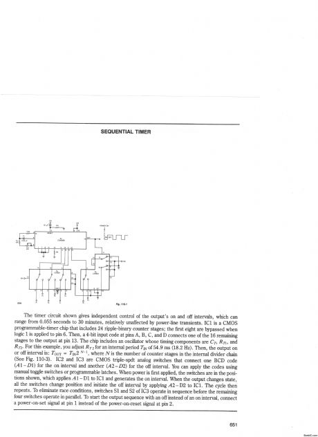
The timer circuit shown gives independent control of the output's on and off intervals, which can range from 0.055 seconds to 30 minutes, relatively unaffected by power-line transients. IC1 is a CMOS programmable-timer chip that includes 24 ripple-binary counter stages; the first eight are bypassed when logic 1 is applied to pin 6. Then, a4-bit input code at pins A, B, C, and D connects one of the 16 remaining stages to the output at pin 13. The chip includes an oscillator whose timing components are CT, RT1, and RT2._For this example, you adjust RT2 for an internal period TlN of 54.9 ms (18.2 Hz). Then, the output on or off interval is: Tour= TIN2 N-1, where N is the number of counter stages in the internal divider chain (See Fig. 110-3). IC2 and IC3 are CMOS triple-spdt analog switches that connect one BCD code (A1 -D1) for the on interval and another (A2-D2) for the off interval. You can apply the codes using manual toggle switches or programmable latches. When power is first applied, the switches are in the positions shown, which applies A1 -D1 to IC1 and generates the on intervat. When the output changes state, all the switches change position and initiate the off interval by applying,42-D2 to IC1. The cycle then repeats. To eliminate race conditions, switches S1 and S2 of IC3 operate in sequence before the remaining four switches operate in parallel. To start the output sequence with an off instead of an on interval, connect a power-on-set signal at pin 1 instead of the power-on-reset signal at pin 2. (View)
View full Circuit Diagram | Comments | Reading(0)
DIGITIZER
Published:2009/7/8 2:12:00 Author:May
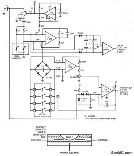
If the tube is level with respect to gravity, the bubble resides in the tube's center and the electrode resistances to common are identical. As the tube shifts avqr from level, the resistances increase and decrease proportionally. Transducers of this type must be excited with an ac waveform to avoid damage to the partially conductive liquid inside the tube.
The level transducer is configured with a pair of 2-KΩ resistors to form a bridge. The required ac bridge excitation is developed at C1A, configured as a multivibrator. C1 biases Q1, which switches the LT1009's 2.5-V potential through the 100-μF capacitor to provide the ac bridge drive. The bridge differential output ac signal is converted to a current by A1, operating as a Howland current pump. This current, whose polarity reverses as bridge drive polarity switches, is rectified by the diode bridge. Thus, the 0.03-μF capacitor receives unipolar charge. A2, running at a differential gain of 2, senses the voltage across the capacitor and presents its single-ended output to C1B. When the voltage across the 0.03-μF capacitor becomes high enough, C1B's output becomes high, turning on the paralleled sections of the LTC1043 switch. This discharges the capacitor. The 47-pF capacitor provides enough ac feedback around CIB to allow a complete zero reset for the capacitor. When the ac feedback ceases, C1B's output decreases and the LTC1043 switch goes off. The 0.03-μF unit again receives constant current charging and the entire cycle repeats. The frequency of this oscillation is determined by the magnitude of the constant current delivered to the bridge-capacitor configuration. This current's magnitude is determined by the transducer bridge's offset, which is level related. (View)
View full Circuit Diagram | Comments | Reading(1145)
| Pages:54/101 At 204142434445464748495051525354555657585960Under 20 |
Circuit Categories
power supply circuit
Amplifier Circuit
Basic Circuit
LED and Light Circuit
Sensor Circuit
Signal Processing
Electrical Equipment Circuit
Control Circuit
Remote Control Circuit
A/D-D/A Converter Circuit
Audio Circuit
Measuring and Test Circuit
Communication Circuit
Computer-Related Circuit
555 Circuit
Automotive Circuit
Repairing Circuit