
Signal Processing
Index 59
1024KHz temperature compensation crystal oscillator circuit diagram
Published:2011/8/9 19:59:00 Author:Sophia | Keyword: 1024KHz temperature compensation, crystal oscillator
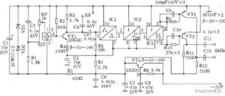
This circuit SJT is 1024kHz temperature compensation crystal oscillator. Circuit theoryis asshown. Because output signal level of the circuit is low, the buffer of follow-up transistor VTl is amplified. VTl base bias resistor R2, the load resistor R3, the emitter resistor R4 are the negative feedback resistors for stablizing VTl DC operating point. Zener diode VDl, VD2, capacitor Cl form stabilivolt and filter circuit to reduce the influency of the supply voltage fluctuations on the frequency of the crystal SJT. Resistors Rl and potentiometer RP TCXO provide bias voltage. regulation of RP can fine-tune the oscillator to reach precise frequency.
(View)
View full Circuit Diagram | Comments | Reading(2046)
Electrical Pulse Therapeutic Apparatus (the 1st)
Published:2011/7/29 4:30:00 Author:Felicity | Keyword: Electrical Pulse, Therapeutic Apparatus
Work of the circuit
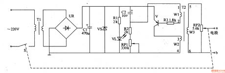
The circuit consists of power circuit and the high-voltage generator circuit. (It is showed in the picture 9-1.)
High-voltage generator circuit is oscillator circuit. The circuit consists of Transistor V, pulse transformers m and related peripheral components. The Oscillation frequency is from 20HZ to dozens Hz.
Change the value of RP1 to change the working frequency of the instrument.
Change the value of RP2 to change the Output pulse amplitude as well as the intensity of electrical pulse. (View)
View full Circuit Diagram | Comments | Reading(847)
Electrical Pulse Therapeutic Apparatus (the 2nd)
Published:2011/7/29 4:30:00 Author:Felicity | Keyword: Electrical Pulse, Therapeutic Apparatus
Work of the circuit
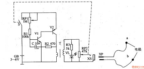
The circuit consists of power switch S, transistors Vl and V2, resistors Rl-R3, light-emitting diode VL, potentiometer RPl and RP2, capacitor C, the output jack XS and pulse transformer T. (It is showed in the picture 9-2.)
When the pulse therapeutic apparatus is working, the shining frequency of VL is same with the frequency of low-frequency oscillator.
Change the value of RP1 to change the frequency of low-frequency oscillator.
Change the value of RP2 to change the intensity of electrical pulse. (View)
View full Circuit Diagram | Comments | Reading(838)
Electrical Pulse Therapeutic Apparatus (the 3rd)
Published:2011/7/29 4:30:00 Author:Felicity | Keyword: Electrical Pulse, Therapeutic Apparatus
Work of the circuit
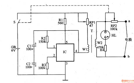
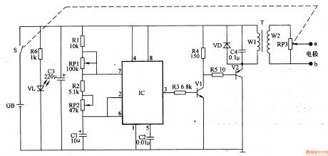
The circuit consists of intermittent oscillator and pulse voltage output circuit. (It is showed in the picture 9-3.)
Intermittent oscillator consists of electronic switch IC, resistors Rl-R3, capacitor Cl and C2, potentiometer RPl and winding Wl of pulse transformer T.
Pulse voltage output circuit consists of T’s winding W2, potentiometer RP2, resistors R4, HL and neon indicator tube electrodes a, b.
Change the value of RP1 to change the intensity of the pulse frequency.
Change the value of RP2 to change the magnitude of the output pulse voltage. (View)
View full Circuit Diagram | Comments | Reading(858)
Electrical Pulse Therapeutic Apparatus (the 7th)
Published:2011/7/29 4:29:00 Author:Felicity | Keyword: Electrical Pulse Therapeutic Apparatus
Work of the circuit
The circuit consists of oscillator, electrical pulse generator and power supply circuit. (It is showed in the picture 9-7.)
The OSC circuit consits of time-baseintegrated circuit IC,resistorsRl, R2,potentiometersRPl, RRobinsonandcapacitor Cl, C2.
Electrical pulse generator consists of resistors R3-R5, transistor Vl, V2, pulse transformer T, the capacitor C4, diode VD, potentiometer RP3 and electrodes a, b.
Power supply circuit consists of Power switch S, batteries GB, current limiting resistor R6, light-emitting diode VL and filter capacitor C3.
Change the value of RP1 and RP2 to change the frequency of the OSC.
Change the vlue of RP3 to chsnge the stimulation of the electrical pulse. (View)
View full Circuit Diagram | Comments | Reading(908)
Voltage Regulator (the 2nd)
Published:2011/7/29 4:27:00 Author:Felicity | Keyword: Voltage Regulator
Work of the circuit
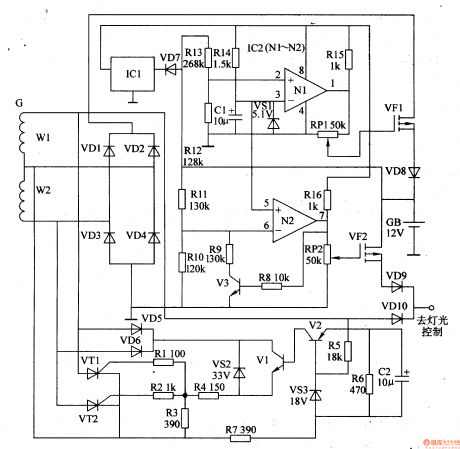
The circuit consists of voluntary stabilizing circuit and battery charging and protecting circuit. (It is showed in picture 7-142.)
Voluntary stabilizing circuitconsists of diodeVD5, VD6,voltage regulatordiodeVS2, VS3,transistorsVl, V2,resistorsRl-R7,capacitorC2 andthyristorVTl, VT2.
Battery charging and protecting circuit consists of capacitor Cl,diodeVDl-VD4, VD7-VDlO,resistorsR8-RlO,potentiometerRPI, RP2,voltage regulatordiodeVSl,transistorsV3,operational amplifierIC2 (Nl, N2,three-terminalvoltage regulatorintegrated circuitICland field-effecttransistorVF1, VF2.
When the speed of the motor is 300Or/min and the AC voltage over W2 is not less than 15V, VT1 and VT2 is transmitted. When thespeed of the motor is low, Vm is cut-off. At the same time, VT1 is transmitted or cut-off. This can stabilize the exporting voltage and make sure the light is bright enough.
When the exporting voltage is over 15V, VF1 is cut-off. In this way, the battery is not over-charged. When the exporting voltage is less than 10.5 V, VF2 is cut-off. In this way, the battery is not over-discharged. Change the value of RP1 and RP2 to change the sensitivity of VF1 and VF2. (View)
View full Circuit Diagram | Comments | Reading(798)
The 400W high power regulated inverter circuit
Published:2011/7/29 4:37:00 Author:Borg | Keyword: high power, regulated inverter circuit

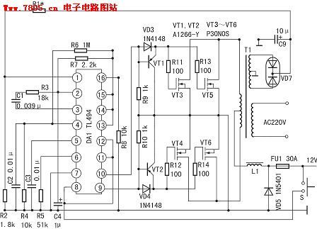
The 400W high power regulated inverter circuit is composed of TL494, whose self-motivation part is TL494,the VT1,VT2,VD3 and VD4 compose the current drive circuit, there are 2 60V/30A MOSFET switch tubes on either drive circuit. If the power needs to be raised ahead, each of the 2 lines can install parallel 3-4 switch tubes and the circuit doesn't change. The usage of TL494 is shown as follows:
(View)
View full Circuit Diagram | Comments | Reading(3376)
74 Series digital circuit of 74LS326 dual VCO(two-way output with controlling)
Published:2011/8/9 3:29:00 Author:Lucas | Keyword: 74 Series , digital circuit , dual VCO, two-way output, controlling
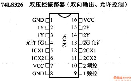
There are two independent voltage-controlled oscillators; output frequency is determined by the external components; it can works at any frequency between 0.12Hz and 30MHZ; it has the complementary output and allowable input end.
(View)
View full Circuit Diagram | Comments | Reading(1326)
74 Series digital circuit of 74LS321 crystal-controlled oscillator
Published:2011/8/1 20:51:00 Author:Lucas | Keyword: 74 Series, digital circuit, crystal-controlled oscillator
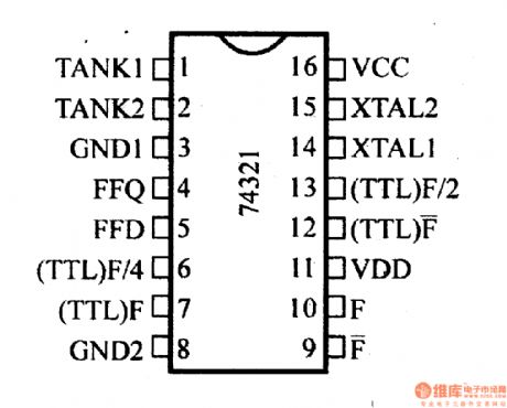

It is similar to 74LS320, but there are two TTL-level outputs by counting F / 2 and F / 4.
(View)
View full Circuit Diagram | Comments | Reading(1248)
The Circuit Diagram of Hepatitis Virus Sterilizer Controller Consists of 555
Published:2011/8/8 21:48:00 Author:Felicity | Keyword: Hepatitis Virus Sterilizer
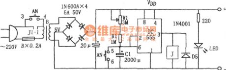
As button AN pressed, the potential transformer B is on and 555 is set because pin 2 is low. And the high voltage output by pin 3 makes contact J1-1 of relay J close and the power voltage is self-hold. Then C1 is charged through W1, R1 and while the voltage reaches 2/3 VDD, 555 reset, and the Contact J1-1 of Relay J releases because the low voltage output by pin 3. And the power is off. And the delay time ,td=1.1(Rw1+R1) C1 ,of 555 is the sterilizing time, which can be adjusted by adjusting W1. (View)
View full Circuit Diagram | Comments | Reading(848)
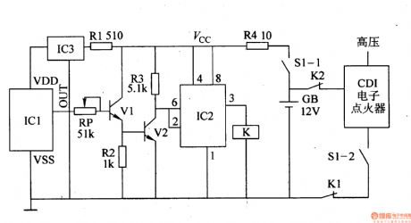
Drunken Driving Limiter (the 1st)
Published:2011/7/29 3:36:00 Author:Felicity | Keyword: Drunken Driving Limiter, the 1st
Work of the circuit
The circuit consists of power circuit, alcoholic testing circuit, amplifying circuit and trigger circuit. (It is showed in picture 7-160.)
Power circuit consists of current limiting resistor R4, Rl, and one end integrated voltage regulator IC3. +12V voltage is limited by R4. Then the voltage works as the working voltage of the trigger and signal amplifier circuit. The is limited by R1 and regulated by IC3. It then turns into +5V and supplied to the alcoholic testing circuit.
Alcoholic testing circuit consists of alcohol (ie ethanol) sensor components ICl and variable resistor RP.
Amplifying circuit consists of transistor Vl, V2 and resistors R2, R3.
Trigger circuit consists of time-base integrated circuit IC2.
When you turn on the switch the power circuit starts to work. When the alcoholic sensory package does not test the sense of alcohol, the car works without interference.
But if the driver is drunk IC1 tests, the sense of alcohol. The voltage of IC1 raises and the trigger is detonated. The high voltage circuit of the car is cut off. The driver cannot start the car. (View)
View full Circuit Diagram | Comments | Reading(739)
Eye-care Lamps (the 3rd)
Published:2011/7/29 3:29:00 Author:Felicity | Keyword: Eye-care Lamps
Work of the circuit
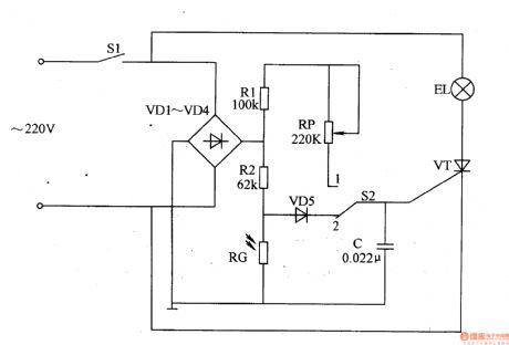
The circuit consists of power switch S1, rectifier diode V1-V4, resistor R1,R2, light-sensitive resistor RG, potentiometer RP, controlling switch S2, capacitor C and light EL (It is showed in picture 9-70.).
Turn on power switch S1 and EL is lightened. When the environmental light is strong, light of EL will become weak. When the environmental light is weak, light of EL will become strong
Put switch S2 in site 1 and the circuit is controlled by people. We can change the value of RP to change the light intensity of the lamp. (View)
View full Circuit Diagram | Comments | Reading(1217)
Memory Strengthener (the 1st)
Published:2011/7/29 3:02:00 Author:Felicity | Keyword: Memory Strengthener
Work of the circuit
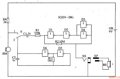
The circuit consists of low-frequency Oscillator, negative feed-back amplifier, mike BM, converting switch S and earphone jack XS. (It is showed in picture 9-75.).
Low-frequency Oscillator consists of six non-gate IC IC (Dl-D6) within the non-gate D5, D6 and resistor R3, capacitor C2.
Negative feed-back amplifier consists of the Dl-D4 within IC and resistor R2.
If you want to use it as a hearing-aid or memory strengthener, you should put S in site 1. Here BM turns the sound signal it collects into electric signal which drives BE to make sound after being adjusted.
If you want to use it as a hypnotizer you should turn S to site 2. Here the signal produced by low-frequency Oscillator will turn to the sound.The sound makes people sleepy after being amplified by negative feed-back amplifier. (View)
View full Circuit Diagram | Comments | Reading(752)
74 Series digital circuit of 74LS325 dual VCO(two-phase output)
Published:2011/8/1 20:34:00 Author:Lucas | Keyword: 74 Series, digital circuit , dual VCO, two-phase output
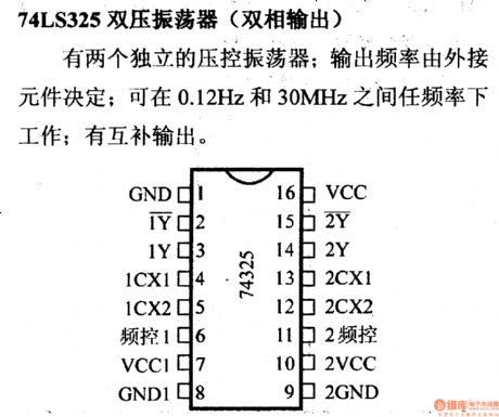
There are two independent voltage-controlled oscillators; output frequency is determined by the external components; it can works at any frequency between 0.12Hz and 30MHZ; it has the complementary output.
(View)
View full Circuit Diagram | Comments | Reading(1217)
Digital lock 7
Published:2011/8/8 3:13:00 Author:Ecco | Keyword: Digital lock
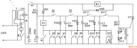
The digital lock circuit is composed of the password control circuit and sound and alarm circuir, and it is shown in Figure 3-104. Password control circuit consists of password buttons SO-S2, thyristors VTl-VT3, resistors Rl-R3, light-emitting diode VL and solenoid YA. Sound and alarm circuit consists of the error buttons S3-S9, thyristor VW, resistors R4-R8, voice integrated circuit ICl, audio power amplifier integrated circuit IC2, voltage regulator diode VS, capacitors Cl-C5 and the speaker BL. Rl-R4 and R6-R8 use the 1/4W carbon film resistors or metal film resistors; R5 select the 1/2W metal film resistor.
(View)
View full Circuit Diagram | Comments | Reading(818)
Mixed circuit applied to the signal distribution
Published:2011/8/7 5:17:00 Author:Sophia | Keyword: Mixed circuit, signal distribution

In the high-frequency circuits, signal distribution using the hybrid circuit is shown in the figure. The so-called hybrid circuit is to achieve the coupling between specific points, while the other points are insulated. Here, it is a experiment against the hybrid circuit among A, B, C, let C → A and C → B signal pass, A → B and B → A will be separated.To simply speaking, in this circuit, A and B will not interfere in each other, and form coupled circuit with C point together. In the hybrid circuit a dual winding coil is used. Here FT-82-43 (25T × 2) is used as experiment. If the surrounding impedance setting is not correct, effective separation will not be acheived.
(View)
View full Circuit Diagram | Comments | Reading(921)
The multivibrator with variable duty cycle circuit diagram composed of Schmitt trigger
Published:2011/8/4 1:56:00 Author:Ecco | Keyword: multivibrator, variable duty cycle, Schmitt trigger
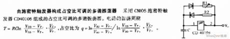
It is the multivibrator with variable duty cycle composed of Schmitt trigger CD40106.
(View)
View full Circuit Diagram | Comments | Reading(976)
PULSE_FREQUENCY_DIVIDER_3
Published:2009/7/14 21:46:00 Author:Jessie
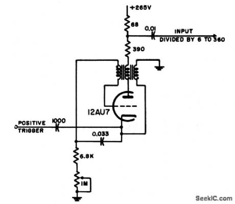
Plate-to-cathode-to-grid coupled blocking oscillator is used to obtain high division ratios for pulses when stability of count is not too important. Lack of fixed bias means that this circuit will free-run in absence of input, but bias can be added if needed.-NBS, Handbook Preferred Circuits Navy Aeronautical Electronic Equipment, Vol. 1, Electron Tube Circuits, 1963, p N7-1. (View)
View full Circuit Diagram | Comments | Reading(811)
SUBAUDIO_FREQUEIICY_METER
Published:2009/7/14 21:52:00 Author:Jessie
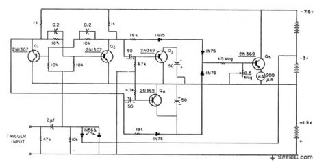
Provides meter indication of frequencies from 0.2 to 10 cps. Responds rapidly to changes in input frequency. Input signal is conyerted to square wave by limiting and differentiating network and bistable flip-lop, with period of square wave indicated on meter calibrated in pulses per minute. By alternately charging each one of pair of capacitors, steady voltage is maintained on capacitor connected to meter while other is charging.-Fast Acting Subaudio Frequency Meter, Electronic Circuit Design Handbook, Mactier Pub. Corp., N.Y., 1965, p 150. (View)
View full Circuit Diagram | Comments | Reading(992)
TEN_FREQUENCY_STANDARD
Published:2009/7/14 21:51:00 Author:Jessie
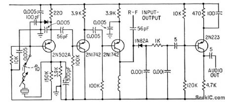
Stable crystal switching oscillator, isolation amplifier, multiplier, mixer, and audio amplifier give choice of ten fundamental frequencies, between 10 and 20 Mc, with harmonic output from 20 to 480 Mc, For zero-boating with unknown input frequency being measured.- Portable Frequency Standard Between 10 and 480 Mc, Electronics, 35:18, p 64. (View)
View full Circuit Diagram | Comments | Reading(856)
| Pages:59/195 At 204142434445464748495051525354555657585960Under 20 |
Circuit Categories
power supply circuit
Amplifier Circuit
Basic Circuit
LED and Light Circuit
Sensor Circuit
Signal Processing
Electrical Equipment Circuit
Control Circuit
Remote Control Circuit
A/D-D/A Converter Circuit
Audio Circuit
Measuring and Test Circuit
Communication Circuit
Computer-Related Circuit
555 Circuit
Automotive Circuit
Repairing Circuit