
Amplifier Circuit
Index 88
400_CPS_MECHANICAL_CHOPPER_AMPLIFIER
Published:2009/7/10 21:53:00 Author:May
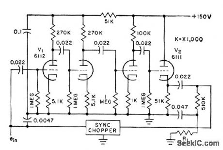
Chopper modulates incoming d-c signal for a-c amplification, then demodulates output synchronously. Conversion gcdn is above 5,000. Suitable for high-goin low-level strcdn.gage thermocouple, and similar signcds where amplifier drift must be minimized without us ing regulated power supply.-L.S. Klivans, D-C Amplifiers for Control Systems, Electronics, 31:47, p96-100. (View)
View full Circuit Diagram | Comments | Reading(784)
Norton_OR_gate_and_NOR_gate_with_high_fan_out
Published:2009/7/17 4:36:00 Author:Jessie
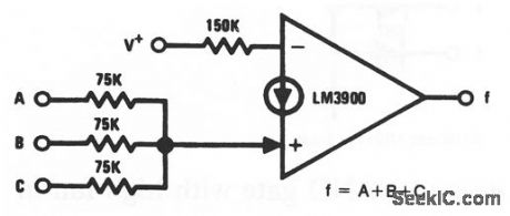
This circuit uses one section of an LM3900 to form an OR gate with a fan out of 50 gates (if each gate has a 75-kΩ input resistor). More than three inputs can be OR' ed if desired. The circuit can be converted to a NOR gate when the inputs are interchanged. National Semiconductor Linear Applications Handbook 1991, p 240 (View)
View full Circuit Diagram | Comments | Reading(693)
SCOPE_PREAMP
Published:2009/7/10 21:45:00 Author:May
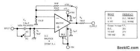
Extends vertical sensitivity range of scope or VOM at minimum cost. Voltage at output is in phase with input. Switch across C gives choice of AC or DC operation.Table gives frequency and output voltage limits. Input impedance is about 500 kilohms.-G.Coers, High-Gain AC/DC Oscilloscope Amplifier, EDN|EEE Magazine, Feb.1,1972, p 56. (View)
View full Circuit Diagram | Comments | Reading(1663)
CURRENT_AMPLIFIER
Published:2009/7/10 21:44:00 Author:May

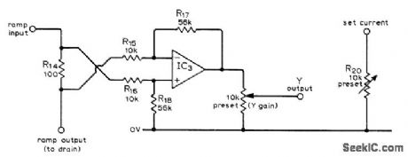
Used in FET curve input tracer to amplify drain current passing through R14, sufficiently to give required Y output for oscilloscope. Uses SN72741P opamp as difference amplifier. Article gives other circuits of curve tracer and calibration procedure.-L. G. Cuthbert, An F.E.T. Curve Tracer, Wireless World,April 1974, p 101-103. (View)
View full Circuit Diagram | Comments | Reading(1176)
ELECTROMETER_FEEDBACK_AMPLIFIER
Published:2009/7/17 4:33:00 Author:Jessie
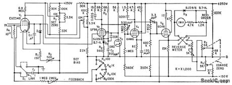
Measures currents in range of 10-11 to 10-15 amp by passing current through high-value precision resistor and amplifying voltage drop across resistor with direct-coupled amplifier of electrometer. British CV2348 is similar to CK5886. Bandwidth is 7.5 Mc. Zener diode D3 provides meter overload protection by damping at about 20% overload.-D. Allenden, Using Feedback in Electrometer Design, Electronics, 32:41, p 71-73. (View)
View full Circuit Diagram | Comments | Reading(1793)
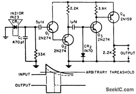
STRONG_NOISE_SUPPRESSING_AUDIO_AMPLIFIER
Published:2009/7/17 4:33:00 Author:Jessie

Feedback circuit limits amplitude of low-frequency signals such as those produced by wind-moved tree branches, to prevent masking vehicular target signals in portable doppler radar. Low-pass filtering compensates for poor bass response of human ear permitting detection of slow-moving targets such as walking man.-J. Scott, D. Randise, and R P. Lukacovic, Portable Radar Traces Battlefield Deployment, Electronics, 33:12, p 67-70.
(View)
View full Circuit Diagram | Comments | Reading(725)
Norton_triangle_wave_generator
Published:2009/7/17 4:30:00 Author:Jessie

This circuit uses one section of an LM3900 to form a triangle-wave generator. Notice that the circuit also produces a square-wave output at the same frequency. National Semiconductor Linear Applications Handbook, 1991, p 233 (View)
View full Circuit Diagram | Comments | Reading(1158)
Norton_pulse_generator
Published:2009/7/17 4:30:00 Author:Jessie
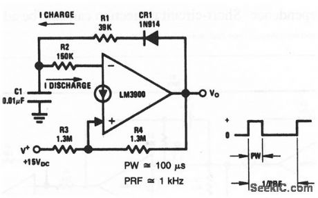
This circuit uses one section of an LM3900 to form a pulse generator (with a 1-kHz pulse repetition rate or frequency, and a 100-μs pulse width). (View)
View full Circuit Diagram | Comments | Reading(804)
LOG_AMPLIFIER
Published:2009/7/17 4:28:00 Author:Jessie
Has highly linear logarithmic output over 30-db dynamic range. Used in obtaining antenna patterns on operating radar system. Output current is directly proportional lo pulse repetition frequency and log of peak r-f pulse power-Logaritthmic Amplifier for Radar Signals, Electronic Circuit Design Handbook, Mactier Pub. Corp., N.Y., 1965, p 107. (View)
View full Circuit Diagram | Comments | Reading(0)
A_C_AMPLIFIER_FOR_SWR_METER
Published:2009/7/17 4:27:00 Author:Jessie
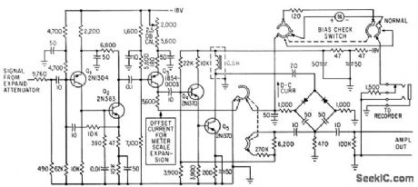
Collector of Q3 provides d-c offset current required for expanding ct segment of the 10-db scale of the meter. Gain adjustment permits any of the four 2.5-db expand ranges to give a full-scale reading.-D. L. Howard, Drift Control Allows Expansion Scales for SWR Meter, Electronics, 35:21, p 45-47. (View)
View full Circuit Diagram | Comments | Reading(742)
EKG_input_amplifier_using_an_optically_coupled_3652_HG_isolation_amplifier_to_protect_the_patent_from_possible_lethal_potentials_
Published:2009/7/17 4:26:00 Author:Jessie
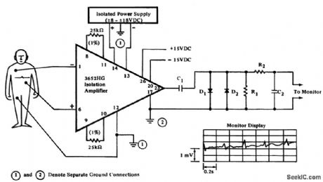
EKG input amplifier using an optically coupled 3652 HG isolation amplifier to protect the patent from possible lethal potentials (courtesy Burr-Brown Research Corporation). (View)
View full Circuit Diagram | Comments | Reading(2489)
Multilead_EKG_recorder_input_circuitry_using_a_284J_isolation_amplifier
Published:2009/7/17 4:25:00 Author:Jessie
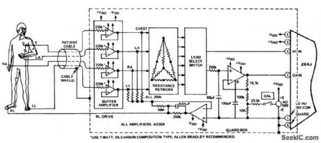
Multilead EKG recorder input circuitry using a 284J isolation amplifier (courtesy Analog Devices, Inc.). (View)
View full Circuit Diagram | Comments | Reading(1322)
Norton_regulator_with_high_voltage_input_protection
Published:2009/7/17 4:24:00 Author:Jessie
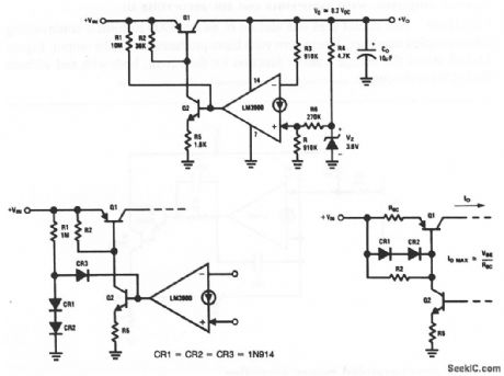
This circuit uses one section of an LM3900 as the control element in a voltage regulator. Q1 and Q2 absorb any high input voltages, and therefore must be high-voltage transistors. With the values shown, the output is about 8.2 V.Diodes can be added (as shown in Fig.11-42B) to reduce ripple feedthrough and input-voltage dependence. Short-circuit protection can also be added, as shown in Fig. 11 -42C. National Semiconductor Linear Applications Handbook, 1991, p. 225 226 (View)
View full Circuit Diagram | Comments | Reading(905)
Isolation_amplifier_for_biomedical_and_industrial_applications
Published:2009/7/17 4:24:00 Author:Jessie
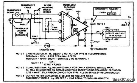
Isolation amplifier for biomedical and industrial applications.(courtesy Analog Devices, Inc.). (View)
View full Circuit Diagram | Comments | Reading(1005)
Norton_direct_coupled_unity_gain_buffer
Published:2009/7/17 4:23:00 Author:Jessie
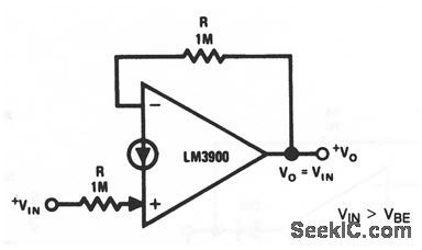
This circuit uses one section of an LM3900 to form a simple direct-coupled unity-gain buffer. Notice that the input voltage must be greater than one VEB (about 0.5 V), but less than the maximum output swing. National Semiconductor. Linear Applications Handbook, 1991 p 224 (View)
View full Circuit Diagram | Comments | Reading(737)
Fetal_heartbeat_monitoring_input_circuitry_using_an_Analog_Devices_284J_isolation_amplifier_
Published:2009/7/17 4:22:00 Author:Jessie
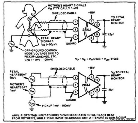
Fetal heartbeat monitoring input circuitry using an Analog Devices 284J isolation amplifier (courtesy Analog Devices, Inc.). (View)
View full Circuit Diagram | Comments | Reading(2327)
Norton_direct_coupled_power_amplifier
Published:2009/7/17 4:20:00 Author:Jessie

This circuit uses one section of an LM3900 and a Darlington pair to provide an output of 3 A into the load. National Semiconductor Linear Applications Handbook 1991, p 223 (View)
View full Circuit Diagram | Comments | Reading(883)
2_W_LM380_POWER_AMPLIFIER
Published:2009/7/10 21:28:00 Author:May
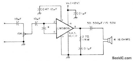
Complete basic circuit for most audio or communication purposes uses minimum of extemal parts. C3, used to limit high frequencies, can be in range of 0.005 to 0.05 F.-A. MacLean, How Do You Use ICs?, 73 Magazine, June 1977, p 184-187. (View)
View full Circuit Diagram | Comments | Reading(790)
Norton_amplifier_with_zero_volts_out_for_zero_volts_in_
Published:2009/7/17 4:19:00 Author:Jessie
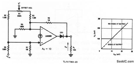
This circuit uses one section or an LM3900 to form a noninverting direct-coupled amplifier, where zero volts input produces zero volts output. Figure 11-39B shows the voltage transfer function for the circuit, both with and without diode CR1 at the output. National Semiconductor Linear Applications Handbook, 1991 p. 222, 223 (View)
View full Circuit Diagram | Comments | Reading(728)
TRANSISTOR_TURNS_OP_AMP_ON_OR_OFF
Published:2009/7/10 21:22:00 Author:May
When transistor Q1 is switched off, the circuit behaves as a voltage follower. By applying a positive voltage to the emitter of Q1 via a 10 Ω resistor, the transistor is made to turn on and go into saturation. Thus, the lower end of R4 is connected to ground. The circuit has not changed into that of a differential amplifier, except that the voltage difference is always 0 V As long as the resistor ratios in the two branches around the op amp are in the same ratio, the output should be zero. A 47-kΩ resistor is used to null out any ratio errors so that the OFF attenuation is more than 60 dB. The high common-mode rejection ratio of a 741 enables this large attenuation to be obtained. (View)
View full Circuit Diagram | Comments | Reading(786)
| Pages:88/250 At 2081828384858687888990919293949596979899100Under 20 |
Circuit Categories
power supply circuit
Amplifier Circuit
Basic Circuit
LED and Light Circuit
Sensor Circuit
Signal Processing
Electrical Equipment Circuit
Control Circuit
Remote Control Circuit
A/D-D/A Converter Circuit
Audio Circuit
Measuring and Test Circuit
Communication Circuit
Computer-Related Circuit
555 Circuit
Automotive Circuit
Repairing Circuit