
Amplifier Circuit
Index 83
ADJUSTABLE_COMPARATOR
Published:2009/7/12 20:52:00 Author:May
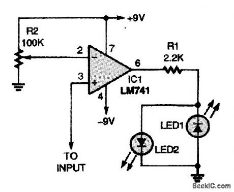
The setting of potentiometer R2 determines the level at which this comparator circuit will switch. The output can be used to drive any device needing a comparator signal, within the drive capabilities of the particular op amp used (741 is shown). (View)
View full Circuit Diagram | Comments | Reading(3720)
FOUR_LEVEL_VOLTAGE_COMPARATOR
Published:2009/7/12 20:52:00 Author:May
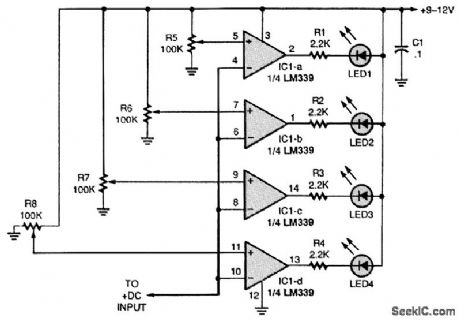
This four-level voltage detector can be used as a bar-graph voltmeter. Simply set each potentiometer (R5 to R8) for a specific voltage. (View)
View full Circuit Diagram | Comments | Reading(3700)
VOLTAGE_WINDOW_COMPARATOR
Published:2009/7/12 20:51:00 Author:May
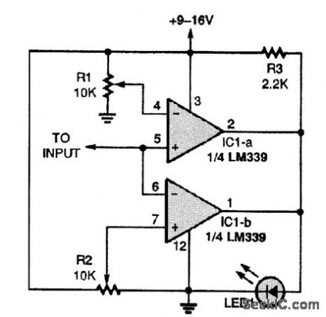
This window comparator determines if a voltage is between two limits, upper and lower.Using a digital voltmeter, set the reference voltages in this voltage window to the same values.Then vary one to set the width of the window; when the input voltage is within the window area, LED1 will light. (View)
View full Circuit Diagram | Comments | Reading(0)
DUAL_VOLTAGE_COMPARATOR
Published:2009/7/12 20:50:00 Author:May
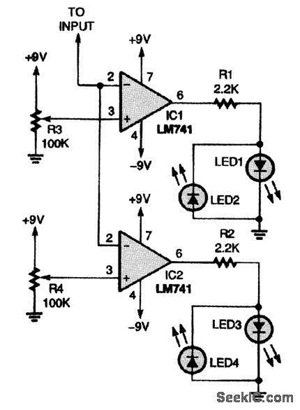
Use this dual comparator to monitor a battery while it's charging; the circuit will let you check for under- and overvoltage conditions.R3 and R4 set the trip levels at which the LEDs are activated. Almost any standard LEDs can be used. LED current is about 3 to 4 mA, as determined by the op-amp capability and resistors R1 and R2. (View)
View full Circuit Diagram | Comments | Reading(2381)
Fast_settling_op_amp_with_gain_of__1
Published:2009/7/19 21:30:00 Author:Jessie
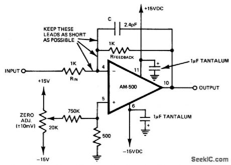
Fast-settling op amp with gain of -1. For gains larger than -1 use an input resistor valued at 500 ohms or less and pick a feedback resistor for the required gain, i.e., 1K for -2, 1.5K for -3, etc. (courtesy Datel Systems, Inc.). (View)
View full Circuit Diagram | Comments | Reading(933)
Norton_noninverting_power_comparator
Published:2009/7/17 4:45:00 Author:Jessie
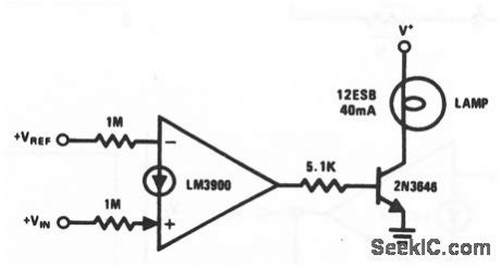
This circuit uses one section of an LM3900 and a 2N3646 to form a noninverting power comparator that is capable of driving a 12-V 40-Ma panel lamp. National Semiconductor, Linear Applications Handbook, 1991 p 243. (View)
View full Circuit Diagram | Comments | Reading(683)
Voltage_controlled_resistor
Published:2009/7/17 3:05:00 Author:Jessie
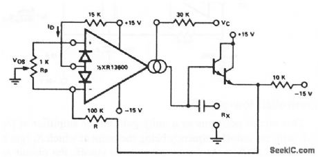
This circuit uses one section of an XR-13600 (Fig. 11-1B) as a single-ended voltage-controlled resistor. A signal applied at RX generates an input to the XR-13600, which is then multiplied by the gm of the amplifier to produce an output current. The resulting resistor or RX = (R + RA)/(gm RA), where gm 19.2 IB at 25℃. Notice that the attenuation of VO by R and RA is necessary to maintain the input within the linear range of the XR-13600 input. EXAP corporation Dalabook 1990 p 5 25 (View)
View full Circuit Diagram | Comments | Reading(1491)
MEMORY_DRIVER_AND_READOUT_AMPLIFIER
Published:2009/7/12 20:41:00 Author:May
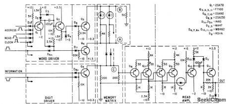
Used with tunnel-diode memory operating 5 Mc.-S. Takahashi and O. Ishii, High-Speed Memory Uses Tunnel Diode Circuit, Electronics,34:42, p66-68. (View)
View full Circuit Diagram | Comments | Reading(698)
SIMPLE_52_kHz_CLOCK
Published:2009/7/12 20:36:00 Author:May
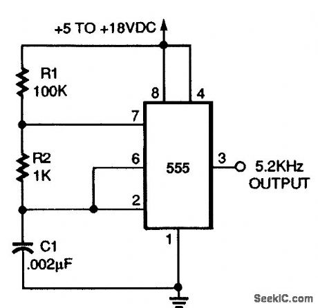
This circuit will produce a clock signal of 5.2 kHz using a NE555 timer. (View)
View full Circuit Diagram | Comments | Reading(714)
TIME_COMPARATOR
Published:2009/7/12 20:35:00 Author:May
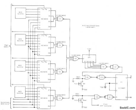
Digital circuit compares time that has been preset on one set of BCD input switches to multiplexed BCD output of basic 24-h industrial clock. When time of day corresponds to preset tifne, output circuit of comparator turns controlled device on for preset period of time. Second set of comparators can be used to tum device off when time of day equals preset time. Only hour and minute digits are compared, using Motorola MC145194-bit AND/OR select ICs, Q output of F1 can be used to control load power through output control circuit driving triac, with optoisolator providing required isolation from AC line. Supply is +5 V.-D. Aldridge and A. Mouton, Industrial Clock/Timer Featuring BackUp Power Supply Operation, Motorola, Phoenix, AZ, 1974, AN-718A,p6. (View)
View full Circuit Diagram | Comments | Reading(1283)
AMMETER_FOR_PRlNTEDCIRCUIT_WIRING
Published:2009/7/12 20:30:00 Author:May

Permits measurement of current in single conductor on board without cutting it. Article gives design of probe having four projecting wires that are pressed on conductor being measured, and describes operation of circuit in detail. Opamp can be 741, but higher-cost 725C will improve performance, When all four wires of probe make contact, voltage drop appears at input of differential amplifier. Outer wires of probe carry current of opposite polarity passing through ammeter; because there is negative feedback loop in conductor, opamp input voltage will return to zero when outgoing current is equal to that of unknown current passing through printed-circuit conductor.-F. An-drews, P.C.B. Ammeter, Wireless World, July 1976, p 34. (View)
View full Circuit Diagram | Comments | Reading(977)
PULSE_COMPARATOR_FOR_TAPE_READER
Published:2009/7/11 5:18:00 Author:May
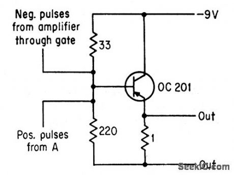
With hole in front of photocell, negative pulse into comparator is much larger than positive drive pulse obtained from GaAs lamp circuit, and comparator delivers negative output pulse.With no hole and no negative pulse, comparator output is positive but same magnitude, because amplifier negative pulses are twice as large as positive input pulses.-R. F. Broom and C. Hilsum, Diode lamp Makes Tope Readers Faster, Electronics, 36:20, p44-45. (View)
View full Circuit Diagram | Comments | Reading(763)
STRETCHER_EXPANDER
Published:2009/7/17 2:03:00 Author:Jessie
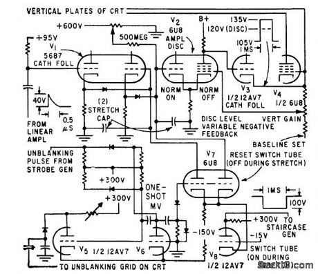
Produces dot pulse and inverted for push that unblanks crt screen and advances staircase.0.5-microsec pulse from linear amplifier is stretched to 2-millisec pulse, amplified and inverted for push-pull crt deflection.-W. E. Bushor, Sample Method Displays millimicrosecond Pulses, 32:31, Electronics, p 69-71. (View)
View full Circuit Diagram | Comments | Reading(713)
FREQUENCY_MULTIPLIER_MMIC_AMPLIFIER
Published:2009/7/17 2:02:00 Author:Jessie
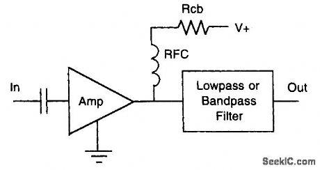
With sufficient drive, an MMIC can be an efficient frequency multiplier. (View)
View full Circuit Diagram | Comments | Reading(747)
GO_NO_GO_BOLTAGE_COMPARATOR
Published:2009/7/11 5:14:00 Author:May
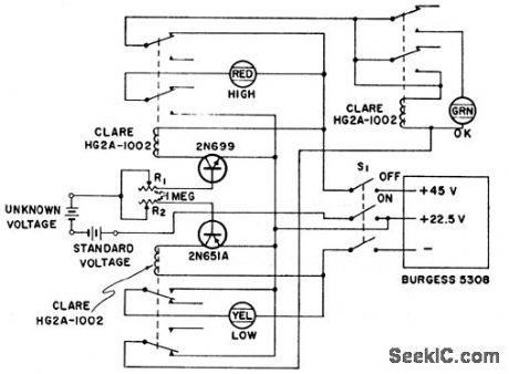
Unknown voltage is compared to standard voltage within preset voltage limits. Circuit is sensitive enough to detect 0.5 v difference.-Trcnsistor Go-No-Go Voltage Comparotor, Electronic Circuit Design Handbook, Mactier Pub. Corp. N.Y. p87. (View)
View full Circuit Diagram | Comments | Reading(777)
HALF_SQUARE_MAGNETIC_MULTIPLIER
Published:2009/7/17 1:55:00 Author:Jessie
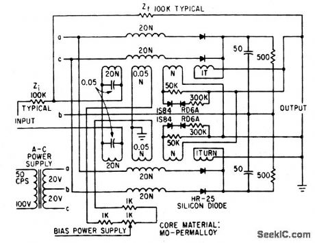
Can be used as squaring function generator, quarter-wave multiplier, or two multipliers. Only one operational amplifier is required.-T. Miura and C. Hirano, Reliable Magnetic Amplifier Improves Multiplier, Electronics, 35:26, p 76-79.
(View)
View full Circuit Diagram | Comments | Reading(873)
REFLEX_KLYSTRON_FREQUENCY_AND_VOLT_AGE_CONTROL
Published:2009/7/17 1:53:00 Author:Jessie
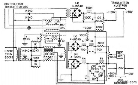
Consists of main regulation magnetic amplifier MA-REG for reflect or VA-222 power klystron in 6,000-Mc microwave link, and secondary magamp MA-AFC that provides further regulation for repeller voltage.-J. Markus, Handbook of Electronic Control Circuits, McGraw-Hill, N.Y., 1959, p 110.
(View)
View full Circuit Diagram | Comments | Reading(2810)
SYNCHRONOUS_SWITCHING_BOOSTS_VOLT_AGE_GAIN
Published:2009/7/17 1:49:00 Author:Jessie
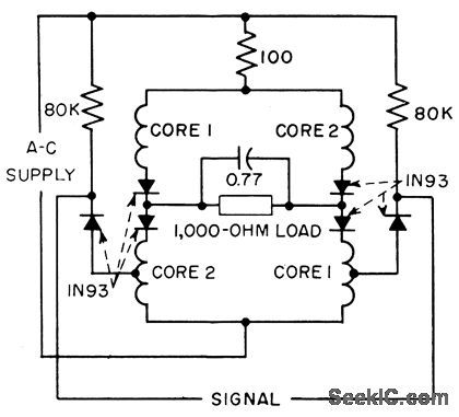
Synchronously switched biased diodes insert impedance in control circuit during power half-cycle. During reset half-cycle bias rectifiers conduct and signal is applied directly across control windings to increase gain by factor of four.-J. Markus, Handbook of Electronic Control Circuits, McGraw.Hill, N.Y., 1959, p 115. (View)
View full Circuit Diagram | Comments | Reading(645)
AMPLITUDE_COMPARATOR
Published:2009/7/11 5:07:00 Author:May
Uses minimum-hysteresis Schmitt trigger (30 my hysteresis) to compare voltage at input B with that at input A Can also be used as variable Schmitt trigger in which input B determines trigger voltage.-M. A. Smither and W. E. Zrubek, Variable Schmitt, Amplitude Comparator, EEE, 14:7, p106. (View)
View full Circuit Diagram | Comments | Reading(1284)
BILATERAL_TRANSISTOR_COMPARATOR
Published:2009/7/11 5:04:00 Author:May
Used as voltage comparator by connecting one input to some reference level and allowing sec ond input to vary. Can also serve as digital comparator in digital computer, to ascertain when two numbers become equal. Output drops to zero when numbers in digital form are equal.-Comparator Uses Bilateral Tran-sistor, Electronic Circuit Design Handbook, Mactier Pub. Corp, N.Y. p91. (View)
View full Circuit Diagram | Comments | Reading(1107)
| Pages:83/250 At 2081828384858687888990919293949596979899100Under 20 |
Circuit Categories
power supply circuit
Amplifier Circuit
Basic Circuit
LED and Light Circuit
Sensor Circuit
Signal Processing
Electrical Equipment Circuit
Control Circuit
Remote Control Circuit
A/D-D/A Converter Circuit
Audio Circuit
Measuring and Test Circuit
Communication Circuit
Computer-Related Circuit
555 Circuit
Automotive Circuit
Repairing Circuit