
Amplifier Circuit
Index 90
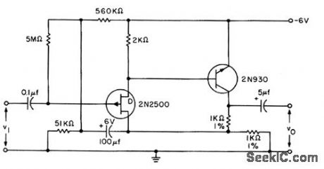
IHREE_FET_A_C_AMPLIFIER
Published:2009/7/10 5:29:00 Author:May
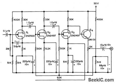
Can be used in applications requiring amplilcation of microvolt signals, as in ultrasensitive preamps for null detectors, medical research equipment, recorders, osciloscopes, and low-level transducers. With 100K generator resistance, amplifier 3-db bandwidth is 1 cps to 40 kc.-L.J. Sevin, Jr., Field-Effect Transislors, McGraw-Hill, N.Y., 1965, p 107.
(View)
View full Circuit Diagram | Comments | Reading(781)
Norton_low_drift_ramp_and_hold
Published:2009/7/17 4:59:00 Author:Jessie
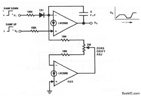
This circuit uses two sections of an LM3900 to form a low-drift ramp-and-hold circuit with a zero-drift adjustment. If both inputs are at zero volts, the circuit is in hold (after proper zero-drift adjustment). Raising either input causes the dc output to ramp up or down, depending on which input goes positive. The ramp slope is a function of the input-voltage magnitude. Additional inputs can be placed in parallel to increase the input-control variables. National Semiconductor, Linear Applications Handbook 1991 p 249 (View)
View full Circuit Diagram | Comments | Reading(874)
Norton_difference_integrator
Published:2009/7/17 4:58:00 Author:Jessie
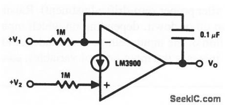
This circuit shows one section of an LM3900 that is used to form a difference integrator. In addition to being the basis for many sweep circuits, this circuit can also provide the time integral of the difference between two input waveforms. This is useful for dc feedback loops because both the comparison to a reference and the integration occur in one amplifier. National Semiconductor linear Applications Handbook 1991 p 248 (View)
View full Circuit Diagram | Comments | Reading(815)
Norton_differentiator
Published:2009/7/17 4:58:00 Author:Jessie
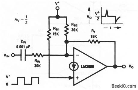
This circuit shows one section of an LM3900 that is used to form a differentiator. Notice that the differentiated output is one-half of the square-wave input. National Semiconductor, Linear Applications Handbook, 1991, p 248 (View)
View full Circuit Diagram | Comments | Reading(679)
Norton_direct_coupled_amplifier_with_±15_V_supplies
Published:2009/7/17 4:52:00 Author:Jessie
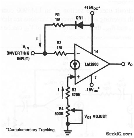
This circuit uses one section of an LM3900 to form a direct-coupled inverting amplifier. The ±15-V supplies must have complementary tracking, and R4 adjust for proper offset (or zero offset) at the output. National semiconductor, Linear Applications Handbook 1991 p 246 (View)
View full Circuit Diagram | Comments | Reading(737)
Norton_ac_amplifier_with_±15__V_supplies
Published:2009/7/17 4:51:00 Author:Jessie
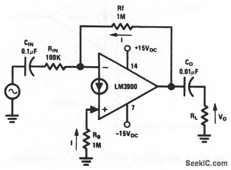
This circuit uses one section of an LM3900 to form an ac-coupled amplifier, where both inputs bias at one VBE above the -VEE voltage (about -15 V). With RF=RB, VO will bias at about 0 V to allow a maximum output swing.Because pin 7 is common to all four amplifiers in the package, the other amplifiers are also biased for operation with ±15-V supplies. National Semiconductor Linear Applications Handbook 1991, p 246 (View)
View full Circuit Diagram | Comments | Reading(669)
Norton_Schmitt_triggers
Published:2009/7/17 4:49:00 Author:Jessie
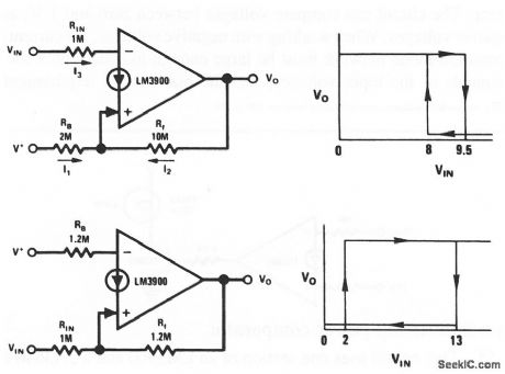
This circuit uses one section of an LM3900 connected to form a Schmitt trigger. Both inverting and noninverting versions are shown. By adjusting the values of RB, RF, and /RIN, the switching values of VIN can be set to any desired levels. National Semiconductor Linear Applications Handbook 1991 p 244 (View)
View full Circuit Diagram | Comments | Reading(781)
173_MC_POWER_AMPLIFIER
Published:2009/7/10 5:28:00 Author:May
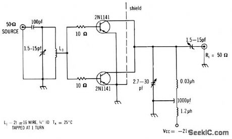
Uses two 2N-1141's in parttllel to deliver average of 400 mw, with power gain of 11.5 db and collector efficiency of 42%. Has excellent large signal performance.-Texas Instruments Inc., Solid-State Communications, McGraw.Hill, N.Y., 1966, p 320. (View)
View full Circuit Diagram | Comments | Reading(693)
WIDEBAND_AMPLIFIER
Published:2009/7/10 5:24:00 Author:May
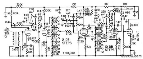
Twin.T ampliler is used between crystal detector and cro of microwave spectrometer for studying electron resonance phenomenon in pctramagnetic materials.-R. R. Unterberger, Microwave Spectrometer Tests Electron Resonance, Elecronics, 32:11, p 142-144.
(View)
View full Circuit Diagram | Comments | Reading(0)
025_W_AMPLIFIER
Published:2009/7/10 5:23:00 Author:May
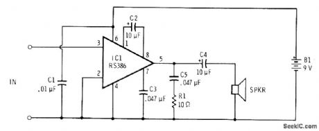
Single Radio Shack RS386 IC powered by 6-9 V from battery provides gain of about 200 with sufficient power to drive 8-ohm loudspeaker when speaking closely into small dynamic microphone of type used with portable tape recorders.-F. M. Mints, Integrated Circuit Projects, Vol. 2, Radio Shack, Fort Worth, TX, 1977, 2nd Ed., p 87-95. (View)
View full Circuit Diagram | Comments | Reading(749)
Weighted_averaging_amplifier_using_half_of_an_ECG947_dual_operational_amplifier
Published:2009/7/19 21:06:00 Author:Jessie
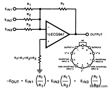
Weighted averaging amplifier using half of an ECG947 dual operational amplifier. The ECG947 is short-circuit protected and requires no external components for frequency compensation (courtesy GTE Sylvania Incorporated). (View)
View full Circuit Diagram | Comments | Reading(608)
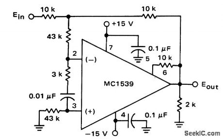
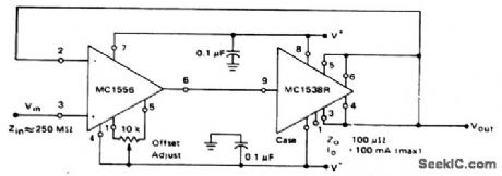
Differential_amplifier_with_low_noise_output_using_an_MC1539_op_amp_
Published:2009/7/19 21:05:00 Author:Jessie
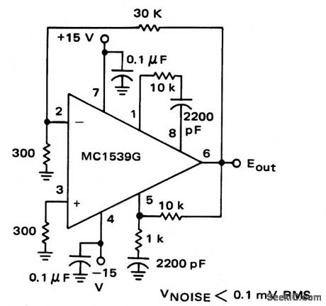
Differential amplifier with low-noise output using an MC1539 op amp (courtesy Motorola Semiconductor Inc.). (View)
View full Circuit Diagram | Comments | Reading(821)
BOOTSTRAPPED_FET_SOURCE_FOLLOWER
Published:2009/7/10 5:18:00 Author:May
Gives 6 db gain for high-impedance transducer output, when 5-meg gate bias resistor is bootstrapped to the source through 100-mfd electrolytic.-L. J. Sevin, Jr., Field-Effect Trclnsislors, Mc Graw-Hill, N.Y., 1965, p 67. (View)
View full Circuit Diagram | Comments | Reading(1140)
Unity_gain_op_amp_with_fast_response_time
Published:2009/7/19 21:05:00 Author:Jessie
Unity-gain op amp with fast response time(courtesy Motorola Semiconductor Products Inc.). (View)
View full Circuit Diagram | Comments | Reading(838)
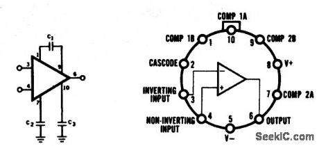
Voltage_comparator_using_an_MC1539G_op_amp
Published:2009/7/19 21:04:00 Author:Jessie
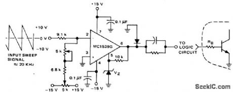
Voltage comparator using an MC1539G op amp (courtesy Motorola Serniconductor Products Inc.). (View)
View full Circuit Diagram | Comments | Reading(630)
High_impedance_high_gain_inverting_amplifier
Published:2009/7/19 21:03:00 Author:Jessie
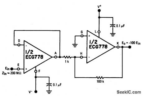
Typical supply voltages are +15 volts and -15 volts (courtesy GTE Sylvania Incorporated). (View)
View full Circuit Diagram | Comments | Reading(1092)
Frequency_compensation_circuit_using_an_ECG915_operational_amplifier
Published:2009/7/19 21:03:00 Author:Jessie
Frequency compensation circuit using an ECG915 operational amplifier. See table for component values. Supply voltage is±15 volts (courtesy GTE Sylvania Incorporated). (View)
View full Circuit Diagram | Comments | Reading(637)
DIRECT_COUPLED_AF
Published:2009/7/10 5:10:00 Author:May
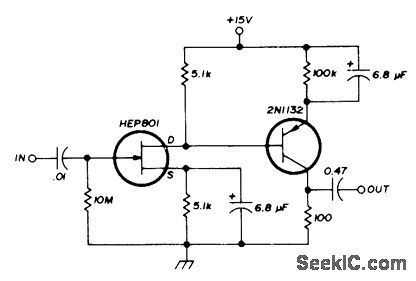
Combination of unipoiar and bipolar transistors gives desirable am plifying features of each solid-state device. Can be used as speech amplifier and for other low-level audio applications.-I. M. Gottlieb, A New Look at Solid-State Amplifiers, Ham Radio, Feb.1976, p 16-19. (View)
View full Circuit Diagram | Comments | Reading(645)
High_impedance_input_high_current_output_voltage_follower
Published:2009/7/19 21:02:00 Author:Jessie
High-impedance input, high-current output voltage follower (courtesy Motorala Semiconduntor Products Inc.). (View)
View full Circuit Diagram | Comments | Reading(695)
High_slew_rate_Power_amplifier_using_an_ECG941_941D_941M_operational_amplifier_
Published:2009/7/19 21:01:00 Author:Jessie
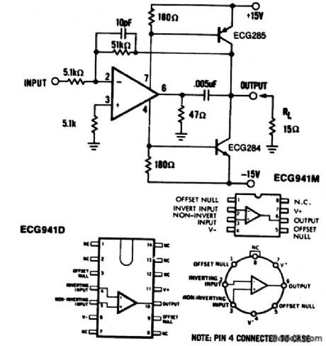
High-slew-rate Power amplifier using an ECG941/941D/941M operational amplifier (courtesy GTE Sylvania Incorporated). (View)
View full Circuit Diagram | Comments | Reading(859)
| Pages:90/250 At 2081828384858687888990919293949596979899100Under 20 |
Circuit Categories
power supply circuit
Amplifier Circuit
Basic Circuit
LED and Light Circuit
Sensor Circuit
Signal Processing
Electrical Equipment Circuit
Control Circuit
Remote Control Circuit
A/D-D/A Converter Circuit
Audio Circuit
Measuring and Test Circuit
Communication Circuit
Computer-Related Circuit
555 Circuit
Automotive Circuit
Repairing Circuit