
Amplifier Circuit
Index 100
STABILIZED_LOW_INPUT_CAPACITANCE_BUFFER
Published:2009/7/9 20:53:00 Author:May
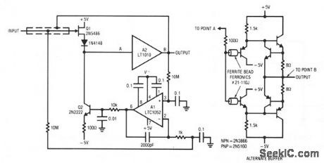
Q1 and Q2 constitute a simple, high-speed FET input buffer. Q1 functions as a source follower, with the Q2 current source load setting the drain-source channel current. The LT1010 buffer provides output drive capability for cables or whatever load is required. Normally, this open-loop configuration would be quite drifty because there is no dc feedback. The LTC1052 contributes this function to stabilize the circuit.It does this by comparing the filtered circuit output to a similarly filtered version of the input signal. The amplified difference between these signals is used to set Q2's bias, and hence Q1's channel current. Q1's source line ensures that the gate never forward biases, and the 2000 pF capacitor at A1 provides stable loop compensation. The rc network in A1's output prevents it from seeing high-speed edges coupled through Q2's collector-base junction. A2's output is also fed back to the shield around Q1's gate lead, bootstrapping the circuit's effective input capacitance down to less than 1 pF. (View)
View full Circuit Diagram | Comments | Reading(873)
2_watt_AF_power_amplifier_for_a_16_ohm_load
Published:2009/7/20 3:54:00 Author:Jessie
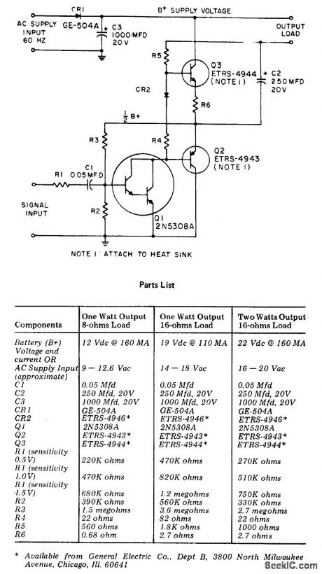
2-watt AF power amplifier for a 16-ohm load (courtesy General Electric Company). (View)
View full Circuit Diagram | Comments | Reading(719)
Complete_cassette_record_playback_circuit_using_an_ECG1110_16_pin_DIP_that_provides_2_watts_of_audio_power
Published:2009/7/20 3:52:00 Author:Jessie
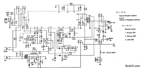
Complete cassette record/playback circuit using an ECG1110 16-pin DIP that provides 2 watts of audio power. This IC includes a preamplifier, tone amplifier and power amplifier. The 2-watt rating is or an 8-ohm load. Recommended supply voltage is 9volts. Typical voltage gains for each section are as follows: preamplifier, 60 dB; tone amplifier, 60 dB; and power amplifier, 40 dB (courtesy GTE Sylvania Incorporated). (View)
View full Circuit Diagram | Comments | Reading(711)
LOW_INPUT_CAPACITANCE_BUFFER
Published:2009/7/9 20:37:00 Author:May
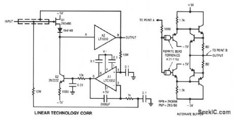
Q1 and Q2 constitute a simple, high-speed FET input buffer. Q1 functions as a source follower, with the Q2 current-source load setting the drain-source channel current. The LT1010 buffer provides output drive capability for cables or whatever load is required. The LTC1052 stabilizes the circuit by comparing the filtered circuit output to a similarly filtered version of the input signal. The amplified difference between these signals is used to set Q2's bias, and hence Q1's channel current. This forces Q1's VGS to whatever voltage is required to match the circuit's input and output potentials. The diode in Q1's source line ensures that the gate never forward biases and the 2000-pF capacitor at A1 provides stable loop compensation. The rc network in A1's output prevents it from seeing high-speed edges coupled through Q2's collector-base junction. A2's output is also fed back to the shield around Q1's gate lead, bootstrapping the circuit's effective input capacitance to less than 1 pF. (View)
View full Circuit Diagram | Comments | Reading(1162)
07_watt_audio_power_amplifier_using_an_ECG1036
Published:2009/7/20 5:03:00 Author:Jessie
0.7-watt audio power amplifier using an ECG1036. Typical voltage gain at 1 kHz is 50 dB. Input impedance is 20K. Frequency response is from 50 hertz to 100 kilohertz (courtesy GTE Sylvania). (View)
View full Circuit Diagram | Comments | Reading(631)
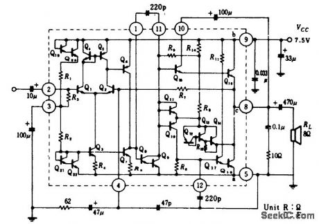
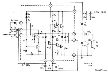
42_watt_AF_power_amplifier_using_an_ECG1153_10_pin_SIP
Published:2009/7/20 5:04:00 Author:Jessie
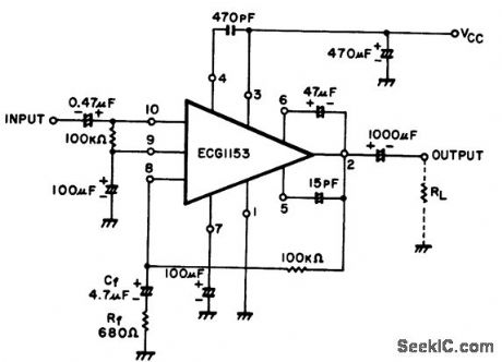
4.2-watt AF power amplifier using an ECG1153 10-pin SIP. Recommended supply voltage is 13.2 volts. The 4.2-watt rating is with a 4-ohm load. Typical voltage gain is 42 dB, Input resistance is 70K (courtesy GTE Sylvania Incorporated). (View)
View full Circuit Diagram | Comments | Reading(644)
2_watts_per_channel_dual_AF_power_amplifiers_using_an_ECG1154_14_pin_DIP
Published:2009/7/20 5:05:00 Author:Jessie
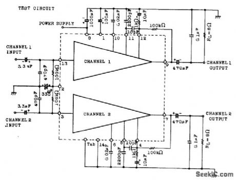
2-watts-per-channel dual AF power amplifiers using an ECG1154 14-pin DIP. Recommended supply voltage is 14 volts. Input resistance is 80K. This circuit is intended for low-cost stereos. Frequency response is from 60 hertz to 30 kilohertz (courtesy GTE Sylvania Incorporated). (View)
View full Circuit Diagram | Comments | Reading(603)
21_watt_AF_power_amplifier_for_phonographs_tape_recorders
Published:2009/7/20 4:56:00 Author:Jessie
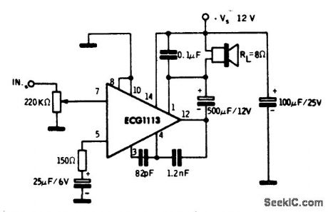
2.1-watt AF power amplifier for phonographs/tape recorders. It is recommended that a 12-volt supply be employed, which makes it ideal for automotive applications. THe ECG1113 is a 14-pin QIP. Current drain at maximum output is 235 mA (courtesy GTE Sylvania Incorporated). (View)
View full Circuit Diagram | Comments | Reading(715)
1_wat_OTL_AF_power_amplifier_using_an_ECG1126_14_pin_DIP_with_tab_Typical_voltage_gain_is_40_dB
Published:2009/7/20 4:52:00 Author:Jessie
1-wat OTL AF power amplifier using an ECG1126 14-pin DIP with tab Typical voltage gain is 40 dB. Maximum current drain is 35 mA (courtesy GTE Sylvania Incorporated). (View)
View full Circuit Diagram | Comments | Reading(660)
13_watt_AF_power_amplifier_using_an_ECG1139_module_and_powered_by_two_16_volt_supplies
Published:2009/7/20 5:02:00 Author:Jessie
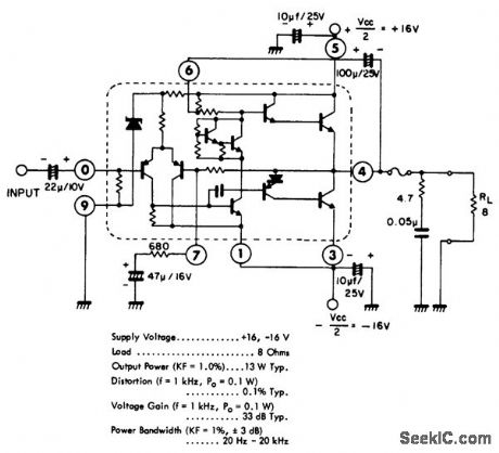
13-watt AF power amplifier using an ECG1139 module and powered by two 16-volt supplies. Use a 2-ampere fuse in the output. Voltage gain is 33 dB (courtesy GTE Sylvania Incorporated). (View)
View full Circuit Diagram | Comments | Reading(728)
600_mW_AF_power_amplifier_for_a_20_ohm_load
Published:2009/7/20 4:59:00 Author:Jessie
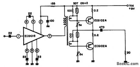
600 mW AF power amplifier for a 20-ohm load. The driver transformer can be purchased locally at Radio Shack (courtesy GTE Sylvania Incorporated). (View)
View full Circuit Diagram | Comments | Reading(652)
13_watt_AF_power_amplifier_using_an_ECG1137_10_pin_TO_99
Published:2009/7/20 4:58:00 Author:Jessie
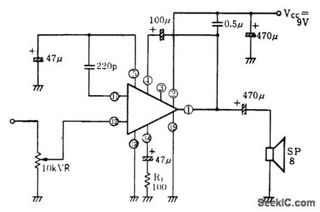
1.3-watt AF power amplifier using an ECG1137 10-pin TO-99. Recommended supply voltage is 10 volts and is to be applied across the 470 μF capacitor. Suggested load for the 1.3-watt output is 8 ohms (courtesy GTE Sylvania Incorporated). (View)
View full Circuit Diagram | Comments | Reading(664)
1_watt_OTL_audio_power_amplifier_with_grounded_load
Published:2009/7/20 4:47:00 Author:Jessie
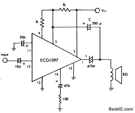
1-watt OTL audio power amplifier with grounded load. The ECG1097 is a 14-pin DIP with tab (courtesy GTE Sylvania Incorporated). (View)
View full Circuit Diagram | Comments | Reading(727)
1__watt_OTL_audio_power_amplifier
Published:2009/7/20 4:47:00 Author:Jessie
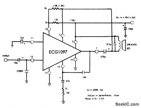
1 -watt OTL audio power amplifier. This amplifier can be operated on 6 volts at a reduced audio output level. Values in parentheses are for 6-volt operation (courtesy GTE Sylvania Incorporated). (View)
View full Circuit Diagram | Comments | Reading(642)
Complete_cassette_record_playback_circuitry_for_low_cost_devices_using_an_ECG1093_14_pin_DIP_with_tab
Published:2009/7/20 4:45:00 Author:Jessie
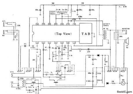
Complete cassette record/playback circuitry for low-cost devices using an ECG1093 14-pin DIP with tab. Typical power output is 1 watt. No signal current drain is 12 mA (courtesy GTE Sylvania Incorporated). (View)
View full Circuit Diagram | Comments | Reading(745)
2_watt_AF_power_amplifier_with_8_ohm_load_connected_to_ground
Published:2009/7/20 4:43:00 Author:Jessie
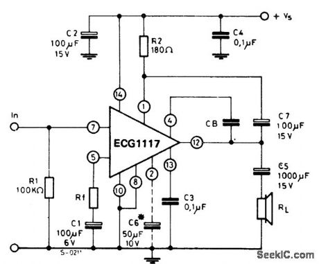
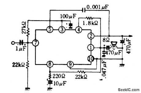
2-watt AF power amplifier with 8-ohm load connected to ground. Rated output of 2 watts is obtained with a power supply voltage of 12 volts. At 9 volts with the same load a rated output of 1.2 watts is obtained. With a 4-ohm load at 9 volts 1.6 watts is obtained. Capacitor C6 must be used when high ripple rejection is required. The ECG1117 is a 14-pin QIP (courtesy GTE Sylvania Incorporated). (View)
View full Circuit Diagram | Comments | Reading(717)
THREE_STAGE_OPAMP
Published:2009/7/9 5:51:00 Author:May
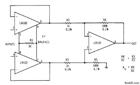
Responds to difference between two applied signals. Differential output voltage of LM102 pair is applied to balanced differential input of LM107 opamp. 0utput can be metered or used in any other desired manner. Voltage gain is equal to ratio R4/R2 and is 100 for values shown.-E. M. Nol!, Linear IC Principles, Experiments, and Projects, Howard W. Sams, Indianapolis, IN, 1974, p 126. (View)
View full Circuit Diagram | Comments | Reading(1017)
45_wad_AF_power_amplifier_using_an_ECG1081
Published:2009/7/20 4:52:00 Author:Jessie
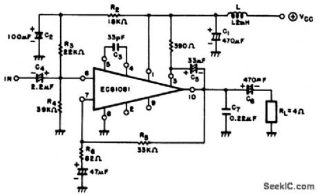
4.5-wad AF power amplifier using an ECG1081. Recommended supply voltage is 13.2 volts, which makes it ideal for automotive applications. Voltage gain at 400 hertz is 50 dB (courtesy GTE Sylvania Incorporated). (View)
View full Circuit Diagram | Comments | Reading(624)
HODOSCOPE_AMPLIFIER
Published:2009/7/9 5:41:00 Author:May
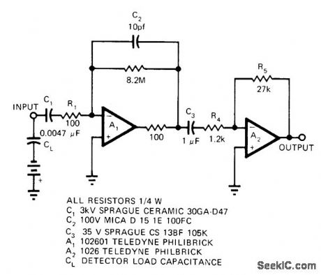
Charge amplifier using Teledyne Philbrick 102601 opamp was developed for use with each Geiger counter of 132-counter array for ionization hodoscope used in tracing paths of cosmic rays. Charge-sensitive stage A1 converts input charge pulse tovoltage pulse significantly larger than noise of second stage. With 616-pF load capacitor, output is 12 V for input of 10 mV. Cost of charge amplifier is about $50.-H. C. Carpenter, Low Cost Charge Amplifier, EDN Magazine, May 20, 1973, p 83 and 85. (View)
View full Circuit Diagram | Comments | Reading(4103)
35_watt_OTL_audio_power_amplifier_using_an_ECG1029
Published:2009/7/20 4:39:00 Author:Jessie
3.5-watt OTL audio power amplifier using an ECG1029. Voltage gain at 1 kHz is 44 dB (courtesy GTE Sylvania Incorporated). (View)
View full Circuit Diagram | Comments | Reading(693)
| Pages:100/250 At 2081828384858687888990919293949596979899100Under 20 |
Circuit Categories
power supply circuit
Amplifier Circuit
Basic Circuit
LED and Light Circuit
Sensor Circuit
Signal Processing
Electrical Equipment Circuit
Control Circuit
Remote Control Circuit
A/D-D/A Converter Circuit
Audio Circuit
Measuring and Test Circuit
Communication Circuit
Computer-Related Circuit
555 Circuit
Automotive Circuit
Repairing Circuit