
Control Circuit
Index 47
MotorCycle Alarms 5 & 6
Published:2012/11/19 1:30:00 Author:muriel | Keyword: MotorCycle Alarms
These are two - easy to build - relay-based alarms. You can use them to protect your motorcycle - but they have many more applications. If you use relays with 6-volt coils - they'll protect your Classic Bike . Both alarms are very small. The completed boards occupy about half a cubic-inch - 8 cc. The standby current is zero - so they won't drain your battery. (View)
View full Circuit Diagram | Comments | Reading(784)
Simple Motorcycle Alarm
Published:2012/11/19 1:29:00 Author:muriel | Keyword: Simple, Motorcycle Alarm
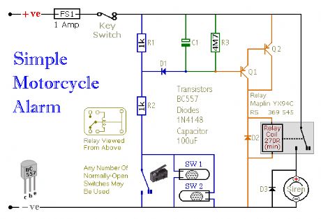
This is a simple - easy to build - transistor based motorcycle alarm. It's designed to work at 12-volts. But - if you change the relay for one with a 6-volt coil - it'll protect your Classic Bike . The standby current is virtually zero - so it won't drain your battery. (View)
View full Circuit Diagram | Comments | Reading(922)
Motorcycle Alarm No. 3
Published:2012/11/19 1:28:00 Author:muriel | Keyword: Motorcycle Alarm
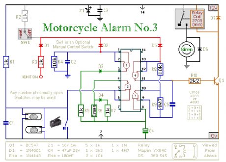
This circuit features an intermittent siren output and automatic reset. It can be operated manually using a key-switch or a hidden switch; but it can also be wired to set itself automatically when you turn-off the ignition. By adding external relays you can immobilize the bike, flash the lights etc. (View)
View full Circuit Diagram | Comments | Reading(1318)
Motorcycle Alarm No. 2
Published:2012/11/19 1:26:00 Author:muriel | Keyword: Motorcycle Alarm
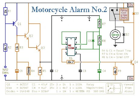
This circuit features an intermittent siren output and automatic reset. It can be operated manually using a key-switch or a hidden switch; but it can also be wired to set itself automatically when you turn-off the ignition. By adding external relays you can immobilize the bike, flash the lights etc. Ron has used my Asymmetric Timer as the basis for his design. (View)
View full Circuit Diagram | Comments | Reading(912)
Snore Alarm
Published:2012/11/19 1:25:00 Author:muriel | Keyword: Snore Alarm
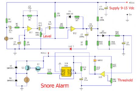
View full Circuit Diagram | Comments | Reading(848)
Hijack Alarm
Published:2012/11/19 1:25:00 Author:muriel | Keyword: Hijack Alarm
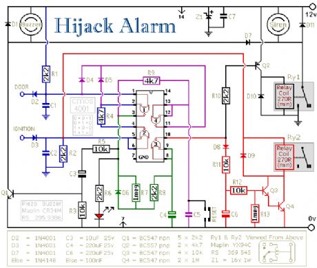
View full Circuit Diagram | Comments | Reading(753)
Car Alarm and Immobilizer
Published:2012/11/19 1:24:00 Author:muriel | Keyword: Car Alarm , Immobilizer
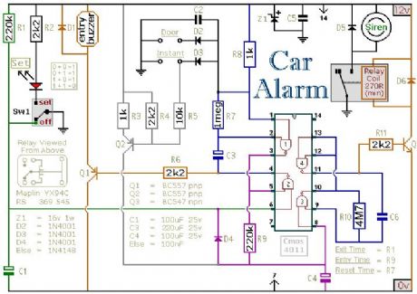
The alarm is set by opening Sw1. It can be any small 1-amp single-pole change-over switch - but for added security you could use a key-switch. Once Sw1 is opened you have about 10 to 15 seconds to get out of the vehicle and close the door behind you. When you return and open the door the buzzer will sound. You have 10 to 15 seconds to move Sw1 to the off position. If you fail to do so, the siren will sound. The output to the siren is intermittent - it switches on and off. The speed at which it switches on and off is set by C6 and R10. While any trigger-switch remains closed, the siren will continue to sound. About 2 to 3 minutes after all of the switches have been opened, the circuit will reset. One of the inputs is connected to the vehicle's existing door-switches. This provides the necessary exit and entry delays. It's usually sufficient to connect a SINGLE wire to just ONE of the door switches - they're generally all connected in parallel with the return through the chassis. You can add extra normally-open switches to the door-circuit if you wish; but note that any additional switches will have to be able to carry the current required by your vehicle's interior light. Any number of normally-open switches may be connected - in parallel - to the Instant input. Since they don't have to carry the current for the interior light, you can use any type of switch you like. You may want an instant alarm on the bonnet, the boot, the rear-hatch, the rear-doors etc. It doesn't matter if these already have switches connected to the door-circuit. Simply fit a second switch and connect it to the instant input. It will override the delay circuit. You can use the chassis for the return. However, a ground terminal is provided if - for any reason - you need to run a separate return wire for either zone. If you're not using the instant zone then leave out Q2, R3, R4, R5 & D3. The exit delay is set by R1 & C1, the entry delay by R9 & C4, and the reset time by R7 & C3. The precise length of any time period depends on the characteristics of the actual components used - especially the tolerance of the capacitors and the exact switching points of the Cmos Gates. However, for this type of application really accurate time periods are unnecessary. The circuit board and switches must be protected from the elements. Dampness or condensation will cause malfunction. Fit a 1-amp in-line fuse AS CLOSE AS POSSIBLE to your power source. This is VERY IMPORTANT. The fuse is there to protect the wiring - not the alarm. Exactly how the system is fitted will depend on the make of your particular vehicle. Consequently, I CANNOT give any further advice on installation. (View)
View full Circuit Diagram | Comments | Reading(1270)
Mini Alarms
Published:2012/11/19 1:23:00 Author:muriel | Keyword: Mini Alarms
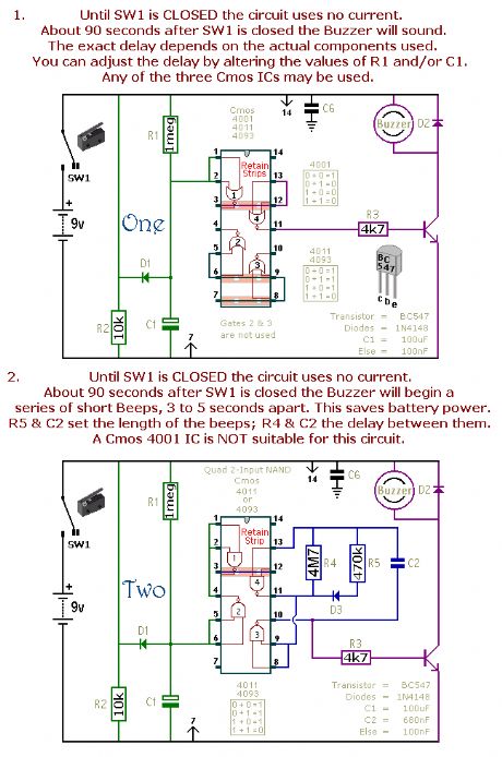
Sw1 is drawn as either a micro-switch or a magnetic-reed contact; but so long as it does the job you can use whatever type of switch you like. Use more than one switch if it suits your application. The output device is a piezo buzzer, requiring a current of about 10mA. Provided the buzzer's voltage is suitable, the circuits will work from 5 to 15-volts. The main features of each alarm are described on the circuit diagram itself. Each pair of circuits will print out on an A4 sheet.The Cmos 4093 is the Schmidt-trigger version of the Cmos 4011. For present purposes the two are interchangeable. However, the 4093 has an improved switching performance that is most noticeable if the time periods are substantially extended.The precise length of any time period will depend on the characteristics of the actual components used; especially the tolerance of the capacitors and the exact switching points of the Cmos Gates.In the case of circuits 11 & 12, treat the values of R6 & R7 as a rough guide. The switching point of Gate 3 and the characteristics of the thermistor will determine the actual temperature range available. Changing the value of R6 will allow you to access different areas of the temperature scale; while changing the value of R7 will allow you to alter the width of adjustment available.Although they are described as alarm circuits, they will have other applications. The buzzer may be replaced by a small relay or an optical isolator; and the timing components may be changed to produce the required output performance. Any relay should have a coil resistance of at least 270 ohms; but for battery operation, the higher the better. If you're using an optical isolator, connect a 1k resistor in series with its LED. (View)
View full Circuit Diagram | Comments | Reading(988)
Single Zone CMOS Alarm
Published:2012/11/19 1:21:00 Author:muriel | Keyword: Single Zone, CMOS Alarm
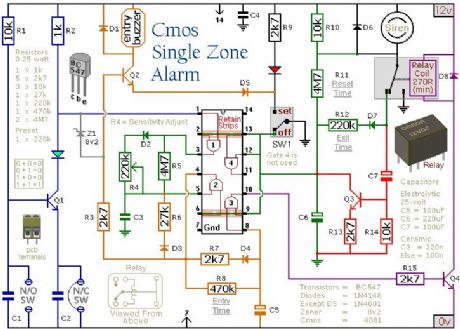
The green Led should be lighting before you set the alarm. When you open SW1 The red Led will light and the Exit delay will begin. You have about 30 to 40 seconds to leave the building. As you do so the buzzer will sound. It should stop sounding when you close the door behind you; indicating that the trigger circuit has been successfully restored within the time allowed. On returning, when you open the door the buzzer will sound again. You then have about 30 to 40 seconds to move SW1 to the off position. If you fail to do so, the siren will sound. After about 15 to 20 minutes, when the relay drops out, the alarm will attempt a Reset by using Q3 to switch itself off briefly. If the trigger circuit has been restored the alarm will reset. If not, the attempt will fail and the alarm will reactivate. It will go on trying to reset itself every 15 to 20 minutes until the trigger circuits are restored; or the alarm is switched off.The Exit delay, Entry delay and Bell Cut-off times may be changed by altering the values of R12, R8 & R11 respectively. The sensitivity of the Inertia Sensors is adjusted by R4. Set to minimum value, a light tap will activate the alarm. Set to maximum value, a heavy blow is required. If you are not using Inertia Sensors then replace R4 with a 220k fixed resistor. If you are not using normally open switches then leave out R1, C1 & Q1 and fit a link between the green Led and C2. (View)
View full Circuit Diagram | Comments | Reading(904)
Single Zone Alarm
Published:2012/11/19 1:20:00 Author:muriel | Keyword: Single Zone, Alarm
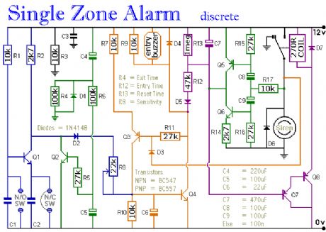
The circuit features automatic exit and entry delays, timed bell cut-off and system reset. It has provision for normally open and normally closed switches and will suit the usual input devices (Pressure Mats, Magnetic Reed contacts, Foil Tape, PIRs and Inertia Sensors). When the power is applied, if there's a fault the buzzer will sound and you should switch off again and check for open doors, windows, etc. If everything is in order the buzzer will NOT sound and the exit delay will begin. You have about 30 seconds to leave the building. When you return the buzzer will sound. You then have about 30 seconds to switch off; otherwise the siren will sound. It will go on sounding indefinitely. However, if the building is re-secured the siren will switch off after about 10 minutes and the alarm will reset.The Exit delay, Entry delay and Bell Cut-off times can be changed by altering the values of R4, R12 & R13 respectively. Q5 and Q6 ensure that the Entry delay and Bell cut-off timers always start with C7 either fully charged or fully discharged as required. If you can live with slightly less precise time intervals then leave out Q5, Q6, R14, R15, R16, R17, C8 & C9. If you don't want a Bell Cut-off at all then leave out D3 as well.The sensitivity of the Inertia Sensors is adjusted by R8. Set to minimum value, a light tap will activate the alarm. Set to maximum value, a heavy blow is required. If you are not using Inertia Sensors then replace R8 with a 27k fixed resistor. If you are not using normally open switches then leave out R1, C1 & Q1 and fit a link between R2 and C2. (View)
View full Circuit Diagram | Comments | Reading(818)
Water Level Alarm
Published:2012/11/19 1:18:00 Author:muriel | Keyword: Water Level , Alarm
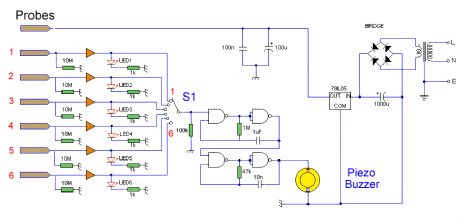
The Conductance of FluidsConductance is the reciprocal of resistance. The conductance of fluids vary with temperature, volume and separation distance ofthe measurement probes. Tap water has a conductance of about 50 uS / cm measured at 25°C. This is 20k/cm at 25°C. See this site for more details about the conductance of fluids.Circuit NotesThis circuit will trigger with any fluid with a resistance under 900K between the maximum separation distance of the probes. Let me explain further. The circuit uses a 4050B CMOS hex buffer working on a 5 volt supply. All gates are biased off by the 10M resistors connected between ground and buffer input. The common probe the topmost probe above probe 1 in the diagram above is onnected to the positive 5 volt supply. If probe 1 is spaced 1 cm away from the common probe and tap water at 25 C is detected between the probes (a resistance of 20k) then the top gate is activated and the LED 1 will light. Similarly if probe 2 at 2 cm distance from the common probe detects water, LED 2 will light and so on. Switch 1 is used to select which output from the hex buffer will trigger the audible oscillator made from the gates of a CMOS 4011B IC. (View)
View full Circuit Diagram | Comments | Reading(2347)
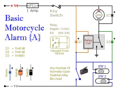
Motorcycle Alarm
Published:2012/11/19 1:18:00 Author:muriel | Keyword: Motorcycle Alarm
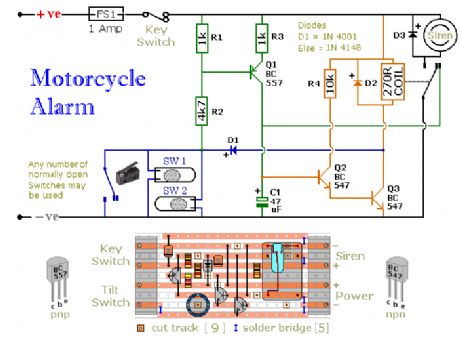
Any number of normally open switches may be used. Fit the mercury switches so that they close when the steering is moved or when the bike is lifted off its side-stand or pushed forward off its centre-stand. Use micro-switches to protect removable panels and the lids of panniers etc. While at least one switch remains closed, the siren will sound. About two minutes after the switches have been opened again, the alarm will reset. How long it takes to switch off depends on the characteristics of the actual components used. But, up to a point, you can adjust the time to suit your requirements by changing the value of C1.The circuit board and switches must be protected from the elements. Dampness or condensation will cause malfunction. Without its terminal blocks, the board is small. Ideally, you should try to find a siren with enough spare space inside to accommodate it. Fit a 1-amp in-line fuse close to the power source. This protects the wiring. Instead of using a key-switch you can use a hidden switch; or you could use the normally closed contacts of a small relay. Wire the relay coil so that it is energized while the ignition is on. Then every time you turn the ignition off, the alarm will set itself.When it's not sounding, the circuit uses virtually no current. This should make it useful in other circumstances. For example, powered by dry batteries and with the relay and siren voltages to suit, it could be fitted inside a computer or anything else that's in danger of being picked up and carried away. The low standby current and automatic reset means that for this sort of application an external on/off switch may not be necessary. (View)
View full Circuit Diagram | Comments | Reading(2508)
4 Digit Alarm Keypad
Published:2012/11/19 1:16:00 Author:muriel | Keyword: 4 Digit, Alarm Keypad
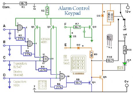
The Keypad must be the kind with a common terminal and a separate connection for each key. On a 12-key pad, look for 13 terminals. The matrix type with 7 terminals will NOT do. The Alarm is set by pressing a single key. Choose the key you want to use and wire it to 'E'. Choose the four keys you want to use to switch the alarm off, and connect them to 'A B C & D'. Your code can include the non-numeric symbols. With a 12-key pad, over 10 000 different codes are available. Wire the common to R1 and all the remaining keys to 'F'. When 'E' is pressed, current through D2 and R9 switches Q5 on. The relay energises, and then holds itself on by providing base current for Q5 through R10. The 12-volt output is switched from the off to the set terminal, and the LED lights. To switch the Alarm off again it is necessary to press A, B, C & D in the right order. The IC is a quad 2-input AND gate, a Cmos 4081. These gates only produce a high output when both inputs are high. Pin 1 is held high by R5. This 'enables' gate 1, so that when 'A' is pressed, the output at pin 3 will go high. This output does two jobs. It locks itself high using R2 and it enables gate 2 by taking pin 5 high. The remaining gates operate in the same way, each locking itself on through a resistor and enabling its successor. If the correct code is entered, pin 10 will switch Q4 on and so connect the base of Q5 to ground. This causes Q5 to switch off and the relay to drop out. Any keys not wired to 'A B C D or E' are connected to the base of Q3 by R7. Whenever one of these 'wrong' keys is pressed, Q3 takes pin 1 low. This removes the 'enable' from gate 1, and the code entry process fails. If 'C' or 'D' is pressed out of sequence, Q1 or Q2 will also take pin 1 low, with the same result. You can change the code by altering the keypad connections. If you need a more secure code use a bigger keypad with more 'wrong' keys wired to 'F'. A 16-key pad gives over 40 000 different codes. All components are shown lying flat on the board; but some are actually mounted upright. The links are bare copper wires on the component side. Two of the links must be fitted before the IC. (View)
View full Circuit Diagram | Comments | Reading(1010)
5 Digit Alarm Keypad
Published:2012/11/19 1:15:00 Author:muriel | Keyword: 5 Digit , Alarm Keypad
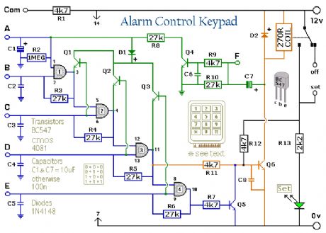
This is an enhanced 5 digit keypad which may be used with the Modular Alarm System.
Circuit NotesThis switch will suit the Modular Burglar Alarm circuit. However, it also has other applications. The Keypad must be the kind with a common terminal and a separate connection for each key. On a 12-key pad, look for 13 terminals. The matrix type with 7 terminals will NOT do. Choose the five keys you want as your code, and connect them to 'A, B, C, D & E'. Wire the common to R1 and all the remaining keys to 'F'. Because your choice can include the non-numeric symbols, almost 100 000 different codes are available. The Alarm is set using the first four of your five chosen keys. When 'A, B, C & D' are pressed in the right order and within the time set by C1 and R2 (about 10 seconds), current through R11 switches Q6 on. The relay energizes, and then holds itself on by providing base current for Q6 through R12. The 12-volt output switches from the off to the set terminal, and the LED lights. To switch the Alarm off again it is necessary to press A, B, C, D & E in the right order. The IC is a quad 2-input AND gate, a Cmos 4081. These gates only produce a high output when both inputs are high. Pressing 'A' takes pin 1 high for a period of time set by C1 and R2. This 'enables' gate 1, so that when 'B' is pressed, the output at pin 3 will go high. This output does two jobs. It locks itself high using R3 and it enables gate 2 by taking pin 5 high. The remaining gates operate in the same way, each locking itself on through a resistor and enabling its successor. If the correct code is entered within the time allowed, pin 10 will switch Q5 on and so connect the base of Q6 to ground. This causes Q6 to switch off and the relay to drop out. Any keys not wired to 'A, B, C, D or E ' are connected to the base of Q4 by R9. Whenever one of these 'wrong' keys is pressed, Q4 takes pin 1 low. This removes the 'enable' from gate 1, and the code entry process fails. If C, D or E is pressed out of sequence, Q1, Q2 or Q3 will also take pin 1 low, with the same result. You can change the code by altering the keypad connections. If you make a mistake entering the code, just start again. If you need a more secure code you can use a bigger keypad with more 'wrong' keys wired to 'F'. A 16-key pad gives over half a million different codes. All components are shown lying flat on the board; but some are actually mounted upright. The links are bare copper wires on the component side. Two of the links must be fitted before the IC. (View)
View full Circuit Diagram | Comments | Reading(643)
Radio Wave Alarm
Published:2012/11/19 1:14:00 Author:muriel | Keyword: Radio Wave , Alarm
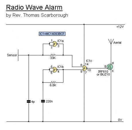
This simple circuit is sure to have the police beating a path to your door- however, it has the added advantage of alerting you to their presence even before their footsteps fall on the doormat.Circuit NotesThe circuit transmits on Medium Wave (this is the small problem with the police). IC1a, together with a sensor (try a 20cm x 20cm sheet of tin foil) oscillates at just over 1MHz. This is modulated by an audio frequency (a continuous beep) produced by IC1b. When a hand or a foot approaches the sensor, the frequency of the transmitter (IC1a) drops appreciably. Suppose now that the circuit transmits at 1MHz. Suppose also that your radio is tuned to a frequency just below this. The 1MHz transmission will therefore not be heard by the radio. But bring a hand or a foot near to the sensor, and the transmitter's frequency will drop, and a beep will be heard from the radio. Attach the antenna to a multiplug adapter that is plugged into the mains, and you will find that the Medium Wave transmission radiates from every wire in your house. Now place a suitably tuned Medium Wave radio near some wires or a plug point in your house, and an early-warning system is set up. Instead of using the sheet of tin foil as the sensor, you could use a doorknob, or burglar bars. Or you could use a pushbutton and series resistor (wired in series with the 33K resistor - the pushbutton would short it out) to decrease the frequency of IC1a, so activating the system by means of a pushbutton switch. In this case, the radio would be tuned to a frequency just below that of the transmitter. (View)
View full Circuit Diagram | Comments | Reading(919)
Water Activated Alarm circuit
Published:2012/11/19 1:13:00 Author:muriel | Keyword: Water , Activated, Alarm circuit
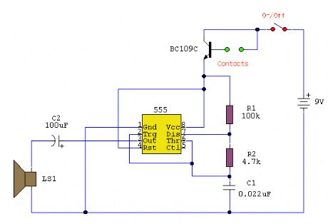
Circuit NotesThe circuit uses a 555 timer wired as an astable oscillator and powered by the emitter current of the BC109C. Under dry conditions, the transistor will have no bias current and be fully off. As the probes get wet, a small current flows between base and emitter and the transistor switches on. A larger current flows in the collector circuit enabling the 555 osillator to sound. An On/Off switch is provided and remember to use a non-reactive metal for the probe contacts. Gold or silver plated contacts from an old relay may be used, however a cheap alternative is to wire alternate copper strips from a piece of veroboard. These will eventually oxidize over but as very little current is flowing in the base circuit, the higher impedance caused by oxidization is not important. No base resistor is necessary as the transistor is in emitter follower, current limit being the impedance at the emitter (the oscillator circuit).
(View)
View full Circuit Diagram | Comments | Reading(1145)
Modular Burglar Alarm
Published:2012/11/19 1:11:00 Author:muriel | Keyword: Modular, Burglar Alarm
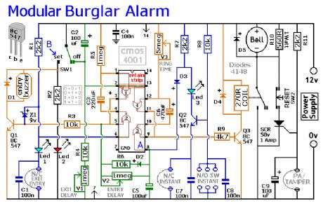
Circuit NotesThis circuit features automatic Exit and Entry delays and a timed Bell Cut-off. It has provision for both normally-closed and normally-open contacts, and a 24-hour Personal Attack/Tamper zone. It is connected permanently to the 12-volt supply and its operation is enabled by opening SW1. By using the expansion modules, you can add as many zones as you require; some or all of which may be the inertia (shock) sensor type. All the green LEDs should be lighting before you open SW1. You then have up to about a minute to leave the building. As you do so, the Buzzer will sound. It should stop sounding when you shut the door behind you. This indicates that the Exit/Entry loop has been successfully restored within the time allowed. When you re-enter the building you have up to about a minute to move SW1 to the off position. If SW1 is not switched off in time, the relay will energise and sound the main bell. It will ring for up to about 40 minutes. But it can be turned off at any time by SW1. The Instant zone has no Entry Delay. If you don't want to use N/O switches, leave out R8, C8 and Q2; and fit a link between Led 3 and C7. The 24 Hour PA/Tamper protection is provided by the SCR/Thyristor. If any of the switches in the N/C loop is opened, R11 will trigger the SCR and the bell will ring. In this case the bell has no time limit. Once the loop is closed again, the SCR may be reset by pressing SW2 and temporarily interrupting the current flow. The basic circuit will be satisfactory in many situations. However, it's much easier to find a fault when the alarm is divided into zones and the control panel can remember which zone has caused the activation. The expansion modules are designed to do this. Although they will work with the existing instant zone, they are intended to replace it. When a zone is activated, its red LED will light and remain lit until the reset button is pressed. All the modules can share a single reset button. (View)
View full Circuit Diagram | Comments | Reading(774)
Miniature Loop Alarm
Published:2012/11/19 1:11:00 Author:muriel | Keyword: Miniature, Loop Alarm
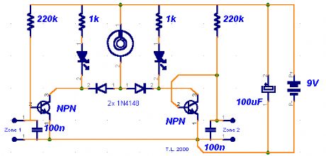
A few months ago, I decided to build a compact, yet effective alarm. My demands were:- simple construction, reliable operation, very small power consumption, and, most of all, small size. I started with CMOS logic gates, but was soon forced to abandon the concept after a few unsuccessful (and far too complicated) attempts. Then I suddenly realized that a simple transistor switch might do the job and I was right.
Circuit Notes:As you can clearly see from the schematics, the circuit is utterly primitive and consists of two identical transistor switches. Each has its own alarm LED and they're coupled to a neat 82dB buzzer. The two 1N4148 diodes are used to prevent a signal from one sensor from triggering both LEDs. The sensors used are either wire loops or normally closed reed switches or even a combination of both. You could, for example, tie a wire loop to your suitcase and place a reed switch to the door of your hotel room.
Since this little alarm is intended to be kept in arms reach at all times, there aren't any provisions for automatic shutdown after a certain period of time. The buzzer will sound until you turn the whole circuit off or connect the wire loop back to the jumpers. The same goes for the two LEDs, each indicating its own zone.
Construction is not critical and there aren't any traps for the novice. The two 100n capacitors aren't really necessary, I just included them to make sure that there is no noise interference coming from the long wire loops. For transistors, you can use any NPN general-purpose audio amplifiers/switches (BC 107/108/109, BC 237/238, 2N2222, 2N3904...). Assemble the circuit on perf board. Together with the buzzer and a 9V battery, it should easily fit in a pocket-sized plastic box smaller than a pack of cigarettes. A fresh battery should suffice for weeks of continuous operation.
(View)
View full Circuit Diagram | Comments | Reading(697)
5 Zone Alarm System
Published:2012/11/19 1:10:00 Author:muriel | Keyword: 5 Zone, Alarm System

This is a complete alarm system with 5 independent zones suitable for a small office or home environment. It uses just 3 CMOS IC's and features a timed entry / exit zone, 4 immediate zones and a panic button. There are indicators for each zone a system armed indicator.
Circuit NotesEach zone uses a normally closed contact. These can be micro switches or standard alarm contacts (usually reed switches). Suitable switches can be bought from alarm shops and concealed in door frames, or window ledges.Zone 1 is a timed zone which must be used as the entry and exit point of the building. Zones 2 - 5 are immediate zones, which will trigger the alarm with no delay. Some RF immunity is provided for long wiring runs by the input capacitors, C1-C5. C7 and R14 also form a transient suppressor. The key switch acts as the Set/Unset and Reset switch. For good security this should be the metal type with a key.OperationAt switch on, C6 will charge via R11, this acts as the exit delay and is set to around 30 seconds. This can be altered by varying either C6 or R11. Once the timing period has elapsed, LED6 will light, meaning the system is armed. LED6 may be mounted externally (at the bell box for example) and provides visual indication that the system has set. Once set any contact that opens will trigger the alarm, including Zone 1. To prevent triggering the alarm on entry to the building, the concealed re-entry switch must be operated. This will discharge C6 and start the entry timer. The re-entry switch could be a concealed reed switch, located anywhere in a door frame, but invisible to the eye. The panic switch, when pressed, will trigger the alarm when set. Relay contacts RLA1 provide the latch, RLA2 operate the siren or buzzer. (View)
View full Circuit Diagram | Comments | Reading(846)
The fishponds hot days hypoxia automatic oxygen control circuit
Published:2012/11/16 2:14:00 Author:Ecco | Keyword: fishponds, hot days, hypoxia , automatic oxygen, control
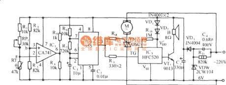
In the hot days, fishponds water temperature also will increase, there is a sharp decline about the oxygen content in water. It is extremely detrimental to the growth of hypoxia on fish, and the added oxygen control circuit will automatically start when the water temperature is higher ( 28 ℃), the water plus oxygen machine is driven by the motor for agitation. The control circuit is composed of thermostat voltage comparing circuit, multivibrator circuit, thyristor motor control circuit, audio sounding circuit and AC buck rectifier circuit and other components, and it is shown in figure.
(View)
View full Circuit Diagram | Comments | Reading(795)
| Pages:47/312 At 204142434445464748495051525354555657585960Under 20 |
Circuit Categories
power supply circuit
Amplifier Circuit
Basic Circuit
LED and Light Circuit
Sensor Circuit
Signal Processing
Electrical Equipment Circuit
Control Circuit
Remote Control Circuit
A/D-D/A Converter Circuit
Audio Circuit
Measuring and Test Circuit
Communication Circuit
Computer-Related Circuit
555 Circuit
Automotive Circuit
Repairing Circuit