
Control Circuit
Index 58
Relay Driver circuit
Published:2012/9/24 4:24:00 Author:muriel | Keyword: Relay,Driver
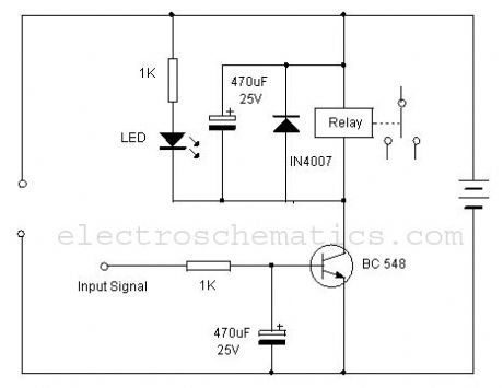
One of the serious problems in relay operated circuits is the relay clicking or chattering during the on/off of the relay driver transistor. This problem is severe if the input circuit is a light / temperature sensor. During the transition of light / temperature levels, the relay clicks which may cause sparking of contacts. By using a simple tip, this problem can be avoided.Below is the circuit of a Relay driver using the NPN transistor BC 548. The relay is connected between the positive rail and the collector of the transistor. When the input signal passes through the I K resistor to the base of the transistor, it conducts and pulls the relay. By adding a 470 uF electrolytic capacitor at the base of the relay driver transistor, a short lag can be induced so that the transistor switches on only if the input signal is persisting. Again,even if the input signal ceases, the transistor remains conducting till the capacitor discharges completely. This avoids relay clicking and the offers clean switching of the relay.
Relay Driver Circuit
(View)
View full Circuit Diagram | Comments | Reading(3063)
Quartz Controlled Bedroom Light Switch
Published:2012/9/24 4:22:00 Author:muriel | Keyword: Quartz,Controlled, Bedroom Light, Switch

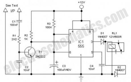
Here is an ultra simple automatic light switch circuit for bedrooms. After construction,connect the input terminals of this circuit in parallel to the internal buzzer terminals of a Quartz-Alarm Clock. When the clock alarm is activated at a time set by the user, electromagnetic relay in the circuit is energised for a short duration, controlled by the timer IC 555.Contacts of the relay can be used to switch on a bedlamp, table lamp or similar electric light loads. The circuit works off unregulated 12V.U se any12VDC/500mA rated standard ac mains adaptor.When the clock alarm rings, input pulses are fed to the trigger input point (T1+Pin2) of IC1, through an RC filter (C1,R1&C2). Here IC1 is wired as a monostable and dc voltage at its output (Pin 3) terminal goes high instantly after receiving a trigger,and remains in the condition for about10 seconds, as configured by the components values of R3 and C3.
Output from IC1 directly drives the low current relay RL1 through diode D1. Note that diode D2 is here used as a freewheeling diode to suppress the counter emf generated during relay switching.
Automatic Light Switch Circuit Schematic
?
7 Responses to “Quartz Controlled Bedroom Light Switch”
(View)
View full Circuit Diagram | Comments | Reading(1978)
Step switch selector
Published:2012/9/24 4:19:00 Author:muriel | Keyword: Step switch, selector
As the name indicates, the step switch selector circuit is intended to choose one of up to four analogue switches, which it does with the aid of some less expensive components. It works off a regulated 5 volt dc supply and draws a current of few milliamperes. It may be used for a variety of applications, such as stepped volume controller, sequential power switcher, and so on. Note that although the prototype uses an ordinary push to on type micro switch, a different kind of sensor may also be used, provided its specification is known and suits the present circuit.
how does the step switch works?
The stepping switch circuit consists basically of a key bouncer, a clock oscillator, 4 stage counter and four analog switches. When power is first applied, the RC network (R5,C4) connected to the reset input (pin15) forces the Q0 output (pin3) of IC2 to be initially active and this standby state is indicated by D2. An oscillator, wired around two gates of IC1, is connected to the clock input(pin 14) of the IC2.
Here, the frequency is near 1Hz with the component values shown (R3=10K & C2=100uF). When S1 is in off state, the counter IC2 remains inactive. If the push to on switch S1 is pressed or when input of the key bouncer circuit( pin11 of IC1) is pulled down, the clock input is enabled at pin 13 of IC2 and the IC counts up at a rate of one count per second.
Stepped switch selector circuit schematic
The counter output state determines the configuration of the four bilateral switches (1 to 4) inside IC3 (4066). When the first pulse is applied to the IC2′s clock input, the Q1 output will be high to trigger switch 1 (IC3A), for the second pulse the Q2 output will be high to trigger switch 2 (IC3B) and so on, sequentially. When the counter reaches its Q5 (pin1) position, the high level at this output resets the counter through resistor R6, switching all bilateral switches of IC3 to off. (View)
View full Circuit Diagram | Comments | Reading(1004)
Appliance Remote Control Arduino Project
Published:2012/9/24 4:16:00 Author:muriel | Keyword: Appliance Remote, Control
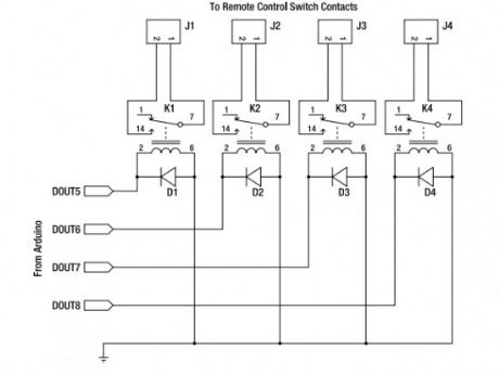
Starting from today I will try to post interesting Arduino projects from around the web. I am novice in this domain but I am giving my best to fully understant it. I must say from the begining that the projects are not developed by me and I will link the original source.
This Arduino project uses a general-purpose appliance remote control that you can buy from a hardware store. It can be modified to link it to an Arduino for software control of devices around your house, without having to touch any mains-level wiring.
Parts required:
1 Arduino Duemilanove, Arduino Pro, Seeeduino, or equivalent
1 RF appliance remote control
1 Prototyping shield
4 5V reed relays
4 1N4001 power diodes or similar
4 PCB-mount male connectors
4 line-mount female connectors
10 cm ribbon cable
Source: http://www.practicalarduino.com/projects/appliance-remote-control
?
One Response to “Appliance Remote Control Arduino Project”
(View)
View full Circuit Diagram | Comments | Reading(2030)
Solar panel to battery switch circuit
Published:2012/9/24 4:13:00 Author:muriel | Keyword: Solar panel, battery switch
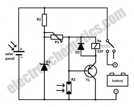
When loading a battery during the day from a solar panel it can be partially discharging through the panel after nightfall. This solar panel power switch circuit replaces the diode and connects the panel to battery through a relay contact. When the power supply voltage is to low the relay is not ON, so the battery is not connected to the solar panel.When the voltage is high enough to engage the relay and the LDR receives enough light in order to open T1, the relay will switch and the battery will charge.
The relay remains ON even when the solar panel voltage starts to decrease. A battery connected and charged can not action the relay when the light intensity decreases because R2 will block T1. The brightness at which this occurs is set by P1.
Because the power consumption is determined primarily by the relay, it is important that it should a miniature one, with high coil resistance but be capable to switch up to 10 A.
Solar panel power switch schematic
Components list for solar panel to battery switchR1 = 100ΩR2 = LDR05P1 = 25KD1 = zener diode 9.1V / 1WD2 = 1N4148T1 = BC557?
7 Responses to “Solar panel to battery switch circuit”
(View)
View full Circuit Diagram | Comments | Reading(1167)
Light sensor switch circuit
Published:2012/9/24 4:12:00 Author:muriel | Keyword: Light sensor,switch
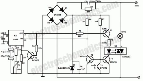
This light sensor switch circuit allows the automatic connection of a lamp when the light is low (at nightfall) and will maintain the lamp ON for a certain period of time.This time can be adjusted with P1 between 1 and 5 hours. The switch is a semiconductor relay S202DS2 and the oscillator is 4060.
Sensor light switch schematic
From the moment that T4 and T5 are opened, relay’s LED start to light and powers the lamp. As soon as one of the transistors is blocked the lamp will go OFF. The phototransistor T3 will be the one that blocks T5 if there is light that falls on T3. The T2′s base-emitter junction is connected in parallel with T3 and so will be blocked as long there is light. T2 will continuously resest IC1 whose counter outputs will be in “0″ state.
When the night falls R7 provides base current for T2 and the transistor starts to conduct. The counter can now starts to count the impulses from the internal oscillator and in this time the light will bulb will stay lit. After a time, when the output of Q13 goes in state “1″ T4 is blocked. This causes the relay’s LED to go off and the lamp too.
There is no need for external power supply because the light sensor switch is powered directly from the 220V mains. D1 … D5 diodes rectifies the voltage and C4 filters it.C5 is working as a resistor so will need to have the working voltage of minimum 400V but the 630V is preferable.
S202DS2 is a Triac-Full-Wave-Output Optocoupler produced by Sharp Electronics in a TO-220 package.
The maximum peak-to-peak voltage is 600V, max on-state current is 8 Ampere and the input trigger current is 8 mA.
Caution! This circuit is powered directly from 220V. Attention will be given for appropriate isolation of the switch block.?
7 Responses to “Light sensor switch circuit”
(View)
View full Circuit Diagram | Comments | Reading(1709)
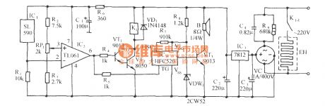
Temperature controlled relay circuit
Published:2012/9/24 4:10:00 Author:muriel | Keyword: Temperature controlled, relay
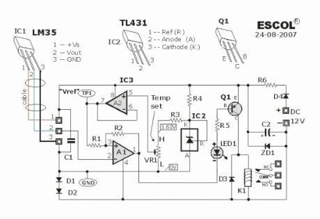
This temperature controlled relay circuit is a simple yet highly accurate thermal control circuit which can be used in applications where automatic temperature control is needed. The circuit switches a miniature relay ON or OFF according to the temperature detected by the single chip temperature sensor LM35DZ.When the LM35DZ detects a temperature higher than the preset level (set by VR1), the relay is actuated. When the temperature falls below the preset temperature, relay is de-energized. The circuit can be powered by any DC 12V supply or battery (100mA min.)
Electronic Temperature-Controlled Relay Schematic
How it works?The heart of the circuit is the LM35DZ temperature sensor which is factory-calibrated in the Celsius (or Centigrade) scale with a linear Degree->Volt conversion function. The output voltage (at pin 2) changes linearly with temperature from 0V (0oC) to 1000mV (100oC).
The preset (VR1) & resistor (R3) from a variable voltage divider which sets a reference voltage (Vref) form 0V ~ 1.62V. The op-amp (A2) buffers the reference voltage so as to avoid loading the divider network (VR1 & R3). The comparator (A1) compares the reference voltage Vref (set by VR1) with the output voltage of LM35DZ and decides whether to energize or de-energize the relay (LED1 ON or OFF respectively).
Source: http://www.escol.com.my/Projects/Project-03%28Thermostat-1%29/Proj-03.html
Components list:
IC1 : LM35DZIC2 : TL431IC3 : LM358
LED1 – 3mm or 5mm LED
Q1 – General purpose PNP transistor ( A1015,…) with E-C-B pin-out)D1, D2 — 1N4148D3, D4 — 1N400x (x=2,,,,.7)
ZD1 — Zener diode, 13V, 400mW
Preset (trim pot) : 2.2K (Temperature set point)R1 – 10KR2 – 4.7MR3 – 1.2KR4 – 1KR5 – 1KR6 – 33Ω
C1 – 0.1 μF ceramic or mylar capC2 – 470 μF or 680 μF electrolytic cap. (16V min)Miniature relay – DC12V DPDT, Coil = 400 Ω or higher ?
2 Responses to “Temperature controlled relay circuit”
(View)
View full Circuit Diagram | Comments | Reading(2156)
Fuel tank oiling liquid level automatic control circuit with frogs sound
Published:2012/9/20 21:30:00 Author:Ecco | Keyword: Fuel tank, oiling liquid level, automatic control , frogs sound
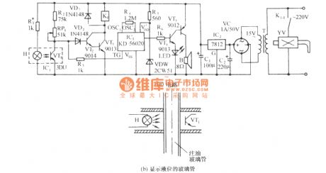
As shown in figure, the circuit is composed of optocoupler, relay control solenoid valve circuit, frogs calling circuit and AC buck rectifier circuit and other components. Typically, the side wall of the tank has a glass tube to display liquid level. If a photocoupler is mounted on the tube ( Figure b ), and it can be moved up and down on the tube, it can achieve the automatic control liquid level of oil filling. When the liquid level reaches the set height, it can also issue frog sound.
(View)
View full Circuit Diagram | Comments | Reading(1509)
Cultural treasures anti-metal closing audible and visual alarm circuit
Published:2012/9/20 21:25:00 Author:Ecco | Keyword: Cultural treasures , anti-metal closing , audible and visual alarm
As shown in the figure, the circuit consists of electromagnetic inductive proximity switch, relay control circuit, whistle analog voice circuit and AC buck rectifier circuit. This circuit can be used for prevention of burglary in museum, artifacts or treasures Collection Room. When someone uses metal artifacts to open the cabinet, the circuit will automatically send alarm whistles and start relay control circuit to turn on the light or camera equipment.
(View)
View full Circuit Diagram | Comments | Reading(1723)
Shadow Alarm Circuit
Published:2012/9/21 2:33:00 Author:Ecco | Keyword: Shadow Alarm
This shadow alarm circuit can sense a moving shadow in a confined area. It can be used to protect things from theft. When somebody approaches the unit, it will give a loud alarm to abort the attempt of theft. The circuit uses the light sensing property of the Photo diode.The circuit uses the light sensing property of the PIN Photodiode. The p-n junction of the photo diode gives light current when it is forward biased. IC1 is designed as a voltage comparator. Its non inverting input is connected to a potential divider R1 and VR. By adjusting VR, input current to pin3 can be set to a reference level. The inverting input of IC1 is connected to a photo diode. IC CA3130 is a 15 MHz BiMOS Operational amplifier with MOSFET inputs and bipolar output. The inputs contain MOSFET transistors to provide very high input impedance and very low input current as low as 10pA. It has high speed of performance and suitable for low input current applications.
CA3130A and CA3130 are op amps that combine the advantage of both CMOS and bipolar transistors. Gate-protected P-Channel MOSFET (PMOS) transistors are used in the input circuit to provide very-high-input impedance, very-low-input current and exceptional speed performance. The use of PMOS transistors in the input stage results in common-mode input-voltage capability down to 0.5V below the negative-supply terminal, an important attribute in single-supply applications.
A CMOS transistor-pair, capable of swinging the output voltage to within 10mV of either supply-voltage terminal (at very high values of load impedance), is employed as the output circuit.
The CA3130 Series circuits operate at supply voltages ranging from 5V to 16V, They can be phase compensated with a single external capacitor, and have terminals for adjustment of offset voltage for application requiring offset-null capability. Terminal provisions are also made to permit strobing of the output stage. The CA3130A offers superior input characteristics over those of the CA3130.
Normally in the light ( as set by VR) Photodiode gives voltage to pin2 of IC1.Since this voltage is higher than the voltage set by VR at pin3 ,output of IC1 remains low keeping LED and buzzer off. When a person approaches the photodiode, the shadow causes a reduction in current through the photodiode so that voltage at pin2 decreases below that of pin3. Output of IC1 then goes high and Buzzer sounds.
NoteThe circuit triggers when the light intensity changes without a shadow. It is better to keep the unit in a place where constant light is available
Shadow Alarm Circuit diagram
?
68 Responses to “Shadow Alarm Circuit”
source: electroschematics.com (View)
View full Circuit Diagram | Comments | Reading(1160)
Water sensor alarm
Published:2012/9/20 20:52:00 Author:Ecco | Keyword: Water sensor, alarm
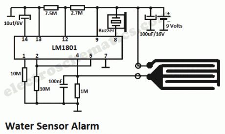
This small water sensor alarm circuit makes a loud warning sound when a humidity sensor detects a quantity of water. This circuit assembly is an application of low power comparator LM1801 made by National Semiconductor. The reference voltage for the integrated circuit is fixed with the help of R2.When pin 4 of the LM1801 voltage exceeds preset threshold, because the moisture sensor noticed a smaller or larger chip will command the active piezoelectric buzzer with a current of over 24 mA.
In the surveillance state, the water sensor alarm circuit has a current consumption of 10 microAmps so you can use a 9V battery for almost one year. We can connect many sensors simultaneously.
Water sensor alarm circuit diagram
?
3 Responses to “Water sensor alarm”
Source: electroschematics.com (View)
View full Circuit Diagram | Comments | Reading(3120)
Timer with alarm circuit
Published:2012/9/20 20:52:00 Author:Ecco | Keyword: Timer , alarm
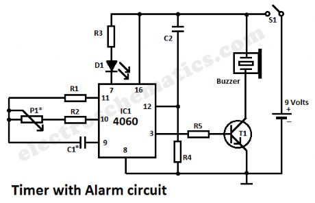
This simple alarm timer circuit is made with 4060 which has an integrated oscillator with a good stability with a relatively wide frequency range. In the circuit diagram the oscillator frequency is set by the RC network that is connected at pins 9, 10 and 11.When the timer with alarm circuit is connected with S1, the pulse from R4 and C2 common point will reset the counter and will start the counting. When it reaches 14 bit, the 13 pin passes in state H and the auto oscillating buzzer is powered by the control transistor T1.
The time interval is adjusted with P1. In order to get intervals ranging from one minute to two hours we should do a proper sizing of the oscillator components:
1 to 30 minutes: C1=220nF; P1=500KΩ
1 to 60 minutes: C1=470nf; P1=500KΩ
1 to 120 minutes: C1=470nF; P1=1MΩ
The power supply of the timer alarm is from a 9V battery. D1 led does not does not affect the operation of the circuit and was included only to show that it works. So, R3 and D1 are optional components.
S1 can be a tilt-sensitive switch with mercury if that will be used as a kitchen clock. With the buzzer on the power consumption of the timer alarm will be around 10 mA.
Timer Alarm circuit diagram
Components valuesP1 = 500kΩ (* read the list above)R1 = 2.2MΩR2 = 18kΩR3 = R5 = 1kΩR4 = 1MΩC1 = 220nF (* read the list above)C2 = 10nFT1 = BC547IC1 = 4060?
4 Responses to “Timer with alarm circuit”
Source: electroschematics.com
(View)
View full Circuit Diagram | Comments | Reading(1608)
Voice control music outlet circuit 1 using NJM2072D
Published:2012/9/19 2:26:00 Author:Ecco | Keyword: Voice control , music outlet
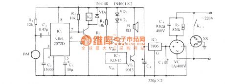
As shown in the figure, the circuit consists of acoustic sensor, voice integrated circuit, relay control circuit, songs sound circuit and AC buck rectifier circuit and other components, it can be used for the voice automatic lights, voice control musical fountain, voice barricades indicator and voice-activated automatic doors. ICl uses voice ASIC NJM2072D, it is the core of the circuit devices, and its functional block diagram is shown in the following figure.
(View)
View full Circuit Diagram | Comments | Reading(1905)
Acousto-optic control lantern with music sound circuit using SH805
Published:2012/9/19 2:18:00 Author:Ecco | Keyword: Acousto-optic control lantern , music sound circuit
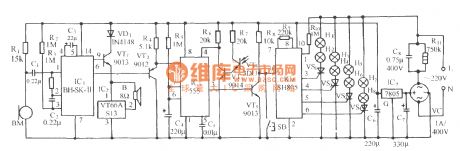
As shown in the figure, the circuit consists of voice switch, light control switch, monostable timing circuit lantern control circuit and music sound circuit. The lamp control circuit has 16 functions of program which can automatically transform colorful light, and its control method is sound and light double control, and it won't be lit during the day, and lit at night. When the the lantern flashes, it is also accompanied by the melodious waltz music.
(View)
View full Circuit Diagram | Comments | Reading(871)
The barn ventilation cooling device circuit using TC626
Published:2012/9/19 2:02:00 Author:Ecco | Keyword: barn , ventilation, cooling device
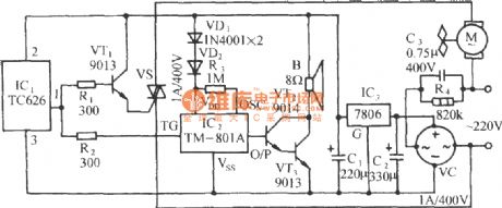
As shown in Figure, the circuit consists of thermostat switch, thyristor control circuit, analog utterance circuit and AC buck rectifier circuit and other components. When the ambient temperature exceeds the set temperature, the circuit can be automatically ventilate and cooling with 3 sound animal sounds.
(View)
View full Circuit Diagram | Comments | Reading(1082)
Gree programmed box fan circuit
Published:2012/9/19 1:40:00 Author:Ecco | Keyword: Gree, programmed , box fan
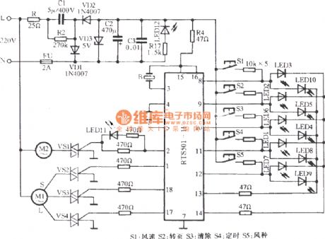
Gree programmed box fan circuit uses monolithic Manifold RTS501-1B and peripheral circuits, and it has a weak, medium, strong wind speeds; ordinary wind, natural wind and sleep wind. It can choose any 9 wind patterns by the combination of wind speed and wind patterns key. The 7.5-hour timing control is set by 0.5 hoursunit accumulating. It is set key beep and self- diagnostic input situation, and each function is corresponding to the light-emitting diode display. The circuit is shown as the figure.
(View)
View full Circuit Diagram | Comments | Reading(1495)
The precious flower greenhouse thermostat control circuit with birdsong sound
Published:2012/9/19 3:36:00 Author:Ecco | Keyword: precious flower, greenhouse , thermostat control , birdsong sound
The circuit is shown as the figure. It consists of a temperature sensor, temperature control circuit, relay control heating circuit, birdsong sound circuit and AC buck rectifier circuit and other components. It enables flowers glasshouse to maintain the set temperature; when it is heating, it can also issue several crisp birdsong.
(View)
View full Circuit Diagram | Comments | Reading(1628)
Smart Heater Controller
Published:2012/9/19 21:51:00 Author:Ecco | Keyword: Smart , Heater Controller
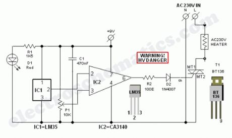
Minuscule circuit of the electronic heater controller presented here is built around the renowned 3-Pin Integrated Temperature Sensor LM35 (IC1) from NSC. Besides, a popular BiMos Op-amp CA3140 (IC2) is used to sense the status of the temperature sensor IC1, which also controls a solid-state switch formed by a high power Triac BT136(T1). Resistive type electric heater at the output of T1 turns to ON and to OFF states as instructed by the control circuit. This gadget can be used as an efficient and safe heater in living rooms, incubators, heavy electric/electronic instrument etc.Normally, when the temperature is below a set value (Decided by multi-turn preset pot P1), voltage at the inverting input (pin2) of IC1 is lower than the level at the non-inverting terminal (pin3). So, the comparator output (at pin 6) of IC1 goes high and T1 is triggered to supply mains power to the desired heater element.When the temperature increases above the set value, say 50-60 degree centigrade, the inverting pin of IC1 also goes above the non-inverting pin and hence the comparator output falls. This stops triggering of T1 preventing the mains supply from reaching the heater element. Forunately, the threshold value is user-controllable and can be set anywhere between 0 to 100 Degree centigrade.The circuit works off stable 9Volt dc supply, which may be derived from the mains supply using a standard ac mains adaptor (100mA at 9V) or using a traditional capacitive voltage divider assembly. You can find such power circuits elsewhere in this website.
Note:CA3140 (IC2) is highly sensitive to electrostatic discharge (ESD). Please follow proper IC Handling Procedures.
Electronic Heater Controller Circuit Schematic
?
2 Responses to “Smart Heater Controller”
Source: electroschematic.com
(View)
View full Circuit Diagram | Comments | Reading(1750)
Warning Alarm circuit with CD4001
Published:2012/9/19 21:49:00 Author:Ecco | Keyword: Warning Alarm
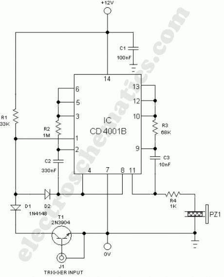
Unorthodox warning alarm circuit presented here is infact a single chip based general purpose sounder, which produces a pulsed alert tone when its input receives a valid trigger signal. The circuit can be easily interfaced with a number of electronic gadgets and sensors and it requires only 12V dc supply input for proper working. A positive level input at trigger point (J1) activates the warning alarm unit.At the heart of the circuit is a popular quad – two input NOR gate IC CD4001, here wired as two independent gated astable multivibrators. Initially, in standby mode, T1 is off and the tone generators are inactive. When T1 is enabled by a proper +ve level trigger signal, pin 1 of CD4001 is pulled low through switching diode D1 first astable block enters in active mode and then activates the second astable block, which is configured as an acoustic alarm. A large piezo-ceramic element (acoustic transducer) at the output of (pin 11) CD4001 will give superb results.
Warning Alarm Circuit Schematic
?
3 Responses to “Warning Alarm circuit with CD4001”
Source: electroschematic.com
(View)
View full Circuit Diagram | Comments | Reading(1387)
Step Alarm Circuit
Published:2012/9/19 21:41:00 Author:Ecco | Keyword: Step Alarm
This Circuit can monitor the door steps or Staircase. When a person crosses the steps, the alarm sounds indicating the entry. The circuit is too sensitive and operates in day light.The circuit uses an NPN Darlington phototransistor L14F1. It senses the intensity of light through its exposed base and passes current in the collector- emitter path. When there is light, the phototransistor conducts and C1 charges up to its full voltage level. The alarm circuit uses a Monostable timer built around IC NE555. The triggering threshold of IC1 is adjusted using VR1. So normally the trigger pin 2 of IC1 remains high as set by VR1. When the shadow of the moving person masks the phototransistor, it turns off allowing C1 to discharge through R1. This momentarily makes the trigger pin 2 of IC1 low and the timing cycle starts. With the given values of R2 and C2, Buzzer sounds for two minutes.
Step Alarm Circuit
SettingThe circuit can be constructed on a small piece of Perf board. The circuit is designed to operate in day light. Switch off the circuit in the evening to avoid false alarm. If a lamp is provided opposite to the phototransistor on the opposite wall of staircase, the circuit can be used as day and night alarm. Align the lamp in the line – of – sight of Phototransistor. Adjust VR1 till the circuit becomes silent.?
8 Responses to “Step Alarm Circuit”
Source: electroschematic.com
(View)
View full Circuit Diagram | Comments | Reading(881)
| Pages:58/312 At 204142434445464748495051525354555657585960Under 20 |
Circuit Categories
power supply circuit
Amplifier Circuit
Basic Circuit
LED and Light Circuit
Sensor Circuit
Signal Processing
Electrical Equipment Circuit
Control Circuit
Remote Control Circuit
A/D-D/A Converter Circuit
Audio Circuit
Measuring and Test Circuit
Communication Circuit
Computer-Related Circuit
555 Circuit
Automotive Circuit
Repairing Circuit