
Control Circuit
Index 53
Single MOSFET Relay Toggle Circuit
Published:2012/10/23 20:16:00 Author:muriel | Keyword: Single MOSFET, Relay , Toggle Circuit
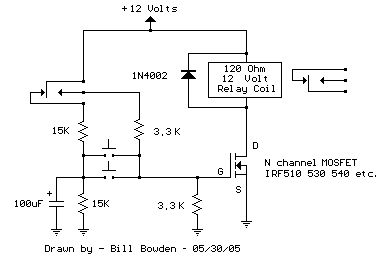
This circuit is similar to the one above, but uses a N channel mosfet such as IRF530, 540, 640, etc. in place of the NPN transistor. Smaller mosfets could be used, but I don't know the part numbers. I tested the circuit with a IRF640, IRFZ44, IRFZ34 and REP50N06.
The circuit has the same three advantages, it requires only a few parts, always comes up with the relay deactivated, and doesn't need any switch debouncing.
In operation, when the relay is deactivated, the 100uF capacitor will charge to 6 volts. When the button is pressed, the capacitor will apply 6 volts to the MOSFET gate turning it on. The capacitor voltage (and gate voltage) will fall from 6 to 3 volts in about 200 mS which should be enough time for the relay contacts to move. For very slow relays, a larger capacitor may be needed.
When the relay energizes, the contacts will apply 12 volts to the 3.3K resistor producing 6 volts at the gate, which will keep the relay energized indefinetly. The capacitor will now discharge to zero since the +12 relay contact is no longer connected to the 15K resistor.
When the button is again pressed, the capacitor will apply zero volts to the gate turning off the relay. There should be no problem holding down the button causing the relay to re-engage since the gate voltage will be only about 1.8 volts when the button is held down and the mosfet requires about 3.5 volts or more to start conducting. But you do need to wait about 1 second or longer between button presses, so the capacitor has time to charge or discharge. Two push buttons are shown, but you could have several more in parallel to control the relay from several different locations. (View)
View full Circuit Diagram | Comments | Reading(1908)
Single Transistor Relay Toggle Circuit
Published:2012/10/23 20:15:00 Author:muriel | Keyword: Single Transistor , Relay , Toggle Circuit

The circuit below requires a double pole, double throw relay in conjunction with a single transistor to allow toggling the relay with a momentary push button. One set of relay contacts is used to control the load, while the other is used to provide feedback to keep the relay activated or deactivated. Several push buttons can be wired in parallel to allow toggling the relay from different locations.
In the deactivated state, the relay contacts are arranged so the 1000 uF capacitor will charge to about 2.7 volts. When the switch is closed, the capacitor voltage is applied to the transistor base through a 560 resistor causing the transistor to turn on and activate the relay. In the activated state, the relay contacts are arranged so the 3.3K resistor and 560 ohm resistor provide a continous current to the transistor base maintaining the activated state. While in the activated state, the capacitor is allowed to discharge to zero through the 1K resistor. When the switch is again closed, the capacitor will cause the transistor base to move toward ground deactivating the relay.
The circuit has three distinct advantages, it requires only a few parts, always comes up with the relay deactivated, and doesn't need any switch debouncing. However since the capacitor will begin charging as soon as the button is depressed, the button cannot remain depressed too long to avoid re-engaging the relay. This problem can be minimized with an additional resistor connected from the transistor base to ground so that the base voltage is close to 0.7 volts with the button depressed and the transistor is biased in the linear region. With the button held down, the relay coil voltage should be somewhere between the pull in and drop out voltages so that the relay will maintain the last toggled state. This worked out to about 820 ohms for the circuit I built using a 12 volt, 120 ohm relay coil and 2N3053 transistor. Temperature changes will effect the situation but the operation is still greatly improved. I heated the transistor with a hair dryer and found that the relay will re-engage with the button held down for approximately 1 second, but this is not much of a problem under normal operation. (View)
View full Circuit Diagram | Comments | Reading(1621)
Relay Toggle Circuit Using a 556 Timer
Published:2012/10/23 20:15:00 Author:muriel | Keyword: Relay Toggle Circuit, 556 Timer
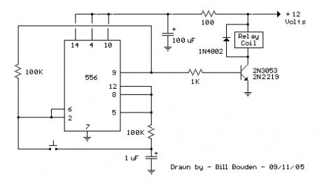
This toggle circuit operates by using a couple 555 timers wired as inverters. Pins 2 and 6 are the threshold and trigger inputs to the first timer and pin 5 is the output. The output at pin 5 will always be the inverse of the input at pins 2 and 6. Likewise, the output at pin 9 of the second timer will always be the inverse of the input at pins 8 and 12. A 100K resistor connects the output of one inverter to the input of the other so the state of one will be the opposite of the other.
In operation, the 1uF capacitor will charge to whatever voltage is present at the output on pin 5. When the button is pressed, the capacitor voltage will be applied to the input of the other timer which will reverse the state of both timers and toggle the relay, either on or off.
To follow it more closely, assume the output at pin 5 is +12 volts and the second output at pin 9 is zero volts. The 1uF cap will be charged to 12 volts. When the button is pressed, the cap will apply +12 to the inputs at pin 2 and 6 which will cause the output at pin 9 to go to zero, turning off the relay. When the button is released, the cap will discharge to zero, since the voltage at pin 5 is now zero. When the button is again pressed, the capacitor will apply zero to pins 2 and 6 causing the output at pin 9 to switch positive and engage the relay, and the cycle repeats.
The advantage of this circuit is the large hystersis range on the inputs. The button can be held closed indefinetly without upsetting the state of the outputs since the input voltage will be 1/2 the supply due to the equal value 100K resistors. The switching points are 1/3 and 2/3 of the supply so that a voltage of 50% has no effect. The circuit will also toggle very fast and needs no switch debouncing. One disadvantage is that it may turn on with the relay either engaged or disengaged. To solve that problem, you could use a resistor in series with one of the reset lines (4 or 10) and add a capacitor from the reset line to ground.
The 100 ohm resistor and 100uF capacitor serve to filter noise on the supply line if the circuit is used in a automotive application. They may not be necessary. The circuit may work well without those parts.
(View)
View full Circuit Diagram | Comments | Reading(2949)
Relay Toggle Circuit Using a 555 Timer
Published:2012/10/23 20:14:00 Author:muriel | Keyword: Relay Toggle Circuit, 555 Timer
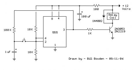
This 555 timer circuit below toggles a relay when a button is pressed. Pins 2 and 6, the threshold and trigger inputs, are held at 1/2 the supply voltage by the two 10K resistors. When the output is high, the capacitor charges through the 100K resistor, and discharges when the output is low. When the button is pressed, the capacitor voltage is applied to pins 2 and 6 which causes the output to change to the opposite state. When the button is released, the capacitor will charge or discharge to the new level at the output (pin 3). The parts are not critical, the resistors can be somewhat higher or lower, but the 2 resistors at pins 2 and 6 should be equal values, and the resistor connected to the cap should be 10 times greater or more.
Advantages of this circuit are the large hystersis range at the input which avoids false triggering, and only a few parts are needed for construction. One disadvantage is the relay may be engaged when power is first applied. To solve this problem, you could tie the reset line (pin 4) to another resistor/capacitor combination with the capacitor at ground and the resistor at the +V point. This will cause pin 4 to be held near ground for a short period which will reset the output when power is applied.
The 100 ohm resistor and 100uF capacitor serve to filter noise on the supply line if the circuit is used in a automotive application. They may not be necessary. The circuit may work well without those parts. (View)
View full Circuit Diagram | Comments | Reading(1874)
Whistle On - Whistle Off
Published:2012/10/22 21:57:00 Author:muriel | Keyword: Whistle On , Whistle Off
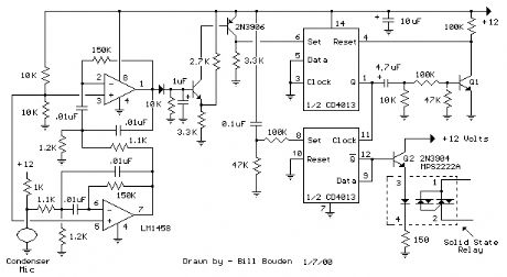
This is an extension of the CMOS toggle flip flop circuit shown in the Circuits controlling relays section with the addition of two bandpass filters and condenser microphone so the relay can be toggled by whistling at it. The condender mic used is a PC board mount Radio Shack #270-090C. The filters are tuned to about 1700 Hz, or the third Ab above middle C on a piano keyboard which is a fairly easy note for me to whistle. Resistor values for the filter can be computed using the three formulas below but we need to assume a gain and Q factor for the filter and the Q of the circuit must be greater than the square root of (Gain/2). The microphone produces only a couple millivolts so the overall gain needs to be around 4000 or around 65 for each filter. The Q or quality factor is the ratio of the center frequency to the bandwidth (-3dB points) and was chosen to be 8 which is greater than 5.7 which is the minimum value for a gain of 65. Both capacitor values need to be the same for easy computation of the resistor values and were chosen to be 0.01uF which is a common value and usable at audio frequencies. From those assumptions, the resistor values can be worked out from the following formulas. (View)
View full Circuit Diagram | Comments | Reading(911)
Quartz Crystal Synchronizer for Pendulum Windup Wall Clock
Published:2012/10/22 21:51:00 Author:muriel | Keyword: Quartz Crystal Synchronizer, Pendulum Windup, Wall Clock
Mechanical Clock Project:Last year, I found a 31 day pendulum wall clock (dissambled) in a box ofparts at a swap meet and decided to try and put it together and regulateit with a quartz crystal oscillator. The escapement part that rocks backand forth and drives the pendulum was missing and had to be made froma couple razor blade pieces and heavy copper wire. The razor blade escapementworked well but only allowed the movement to advance as the pendulum swung,and would not sustain the pendulum motion by itself. But this wasn't aproblem since the quartz crystal divider circuit provides energy to thependulum with an electromagnet to keep it swinging with only a 5 seconderror per day. The 31 day mainspring was included, but I wanted to use aweight and drive wheel in place of the spring.The clock movement is made in Korea by Sau Jin LTD Dae Woo CO LTD and has no jewels. It measures 4.5 inches diameter by 1.5 inchesdeep plus 1.5 inches for the hands and drive wheel shafts, so the clockface and hands are about 3 inches from the wall. The pendulum periodis close to 53.4 complete swings per minute. Can't figure out why thatparticular period was used. I have seen similar movements on ebay.The clock pendulum was made using a 10 inch, 3/16 wooden dowel with astrong magnet attached to the bottom and a small weight near the topto adjust the period close to 53 beats per minute. The circuit boardand electromagnet to drive the pendulum are located on a small shelf(not shown) and positioned so the pendulum magnet swings close to thestationary electromagnet and receives a small pulse on each swing tosustain oscillation. The pulse duration is about 5% of the pendulumperiod and a LED is used to indicate the pulse output. The clock startsfairly easily by releasing the pendulum near the magnet when theLED flash is observed. (View)
View full Circuit Diagram | Comments | Reading(1502)
Light Level Indicator Using a Window Comparator
Published:2012/10/22 21:50:00 Author:muriel | Keyword: Light Level , Indicator, Window Comparator
The second example below uses a LDR (light dependent resistor) to indicatesome desired light level. The LDR has a large dynimic range and varies inresistance from less than 100 ohms on a cloudy day to over a megohm in totaldarkness. A 2K pot was used to adjust the window range for usual room lightconditions. This setup might also be used to indicate sunrise/sunset conditions. (View)
View full Circuit Diagram | Comments | Reading(1727)
Temperature Range Indicator Using a Window Comparator
Published:2012/10/22 21:49:00 Author:muriel | Keyword: Temperature Range , Indicator, Window Comparator
A window comparator usually employs 2 comparators with one output indicatingthe input is somewhere between two limits. In these examples, a thirdcomparator is added to display all three conditions where the input is inthe center range, or higher, or lower.The first example uses a thermistor to indicate the temperature is near68 degrees within about +/- 5 degree tollerance. The thermistor measures33K at around 68 degrees and varies about 3570 ohms over a range of 10 degrees.Using a 12 volt supply, the thermistor voltage will be 6 volts in the centerof the range. As the temperature increases 10 degrees, the total resistancefalls 3750 ohms, the current will be 12/ (66K -3750) =193uA and the thermistorvoltage will be 193u * (33k -3750) = 5.65 volts. This represents a voltagechange of (6 - 5.65) = 350 millivolts for a 10 degree change. The center resistorof the window voltage divider must then drop 350 millivolts. Using 20K resistorson the top and bottom of the window voltage divider produces a current of(6 - (.350/2)) / 20K = 291uA, and the center resistor is .350/291u = 1.2KWhen the temperature is in the center of the window range, the voltage atpins 5 and 6 will be 1/2 the supply voltage, or 6 volts in this case.The voltage divider (20K, 1.2K, 20K) produces a voltage of around 5.8 atpin 4 and 6.2 at pin 7. Since the voltage at pin 5 (6 volts) is more positivethan the voltage at pin 4 (5.8 volts), the output at pin 2 will be a highlevel. At the same time, the voltage at pin 7 (+ input) is higher thanpin 6 (- input) causing pin 1 to also be a high level. This conditionproduces a high (12 volt) level at pin 10 (- input) which produces a lowlevel at pin 13, lighting the window LED indicating the temperature is inthe window range. As the thermistor voltage moves above the upper 6.2 limit,pin 1 will switch low, extinguishing the window LED and illuminating the(Low Temp) LED. Similar action happens as the thermistor voltage moves belowthe lower 5.8 limit causing pin 2 to switch low (Over Temp LED) while theother two LEDs remain off. (View)
View full Circuit Diagram | Comments | Reading(2051)
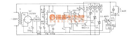
Gas smoke alarm circuit
Published:2012/10/21 20:41:00 Author:Ecco | Keyword: Gas smoke alarm
TGS308 gas sensor conductance ( Figure 5.18 ) increases in the event of combustible gas, and the voltage is got by the potentiometer RP1 slide point, and its value is increased from normal 3V rms to 20V, this elevated voltage is added to transistor VT1 by diode and 4.7kΩ resistor, so that it gets conduction, VT1 conduction makes Triacs 2N6070A get conduction. Thus, full-wave AC voltage can drive E to produce up to 90dB alarm sound. H is Deltal6003168 type 24V AC alarm. When gas disappears from the sensor, the circuit is restored to the original state, so the alarm automatically stops.
(View)
View full Circuit Diagram | Comments | Reading(1020)
Colorful circulation lantern control circuit associated with the Music Box Dance
Published:2012/10/22 2:34:00 Author:Ecco | Keyword: Colorful circulation lantern , control , Music Box Dance
It consists of a time-base pulse generator, count / divider circuit, SCR trigger control lantern circuit, songs sound circuit and AC buck rectifier circuit and other components. It will set red, green, blue three primary colors of light in a matte shade, according to the principle of three primary colors, it can control the count frequency circuit, then the tricolor lights automatically display the red, blue, green, purple, blue, yellow, white seven colors in a rolling cycle. At the same time, it also issues a beautiful music box dance. The circuit uses fewer components with low cost, and it can be used for advertising lights, ballroom lights, family Dream lamps and supplier cupboard decorative lights. The circuit uses AC buck rectifier power supply.
(View)
View full Circuit Diagram | Comments | Reading(1089)
Thermostat for 1KW Space Heater (SCR controlled)
Published:2012/10/22 1:30:00 Author:muriel | Keyword: Thermostat, 1KW, Space Heater , SCR controlled
Below is a thermostat circuit I recently built to control a 1300 watt space heater. The heater element (not shown) is connected in series with two back to back 16 amp SCRs (not shown) which are controlled with a small pulse transformer. The pulse transformer has 3 identical windings, two of which are used to supply trigger pulses to the SCRs, and the third winding is connected to a PNP transistor pair that alternately supply pulses to the transformer at the beginning of each AC half cycle. The trigger pulses are applied to both SCRs near the beginning of each AC half cycle but only one conducts depending on the AC polarity.
DC power for the circuit is shown in the lower left section of the drawing and uses a 1.25uF, 400 volt non-polarized capacitor to obtain about 50mA of current from the AC line. The current is rectified by 2 diodes and used to charge a couple larger low voltage capacitors (3300uF) which provide about 6 volts DC for the circuit. The DC voltage is regulated by the 6.2 volt zener and the 150 ohm resistor in series with the line limits the surge current when power is first applied.
The lower comparator (output at pin 13) serves as a zero crossing detector and produces a 60 Hz square wave in phase with the AC line. The phase is shifted slightly by the 0.33 uF, 220K and 1K network so that the SCR trigger pulse arrives when the line voltage is a few volts above or below zero. The SCRs will not trigger at exactly zero since there will be no voltage to maintain conduction.
The upper two comparators operate in same manner as described in the Electronic thermostat and relay circuit. A low level at pin 2 is produced when the temperature is above the desired level and inhibits the square wave at pin 13 and prevents triggering of the SCRs. When the temperature drops below the desired level, pin 2 will move to an open circuit condition allowing the square wave at pin 13 to trigger the SCRs.
The comparator near the center of the drawing (pins 8,9,14) is used to allow the heater to be manually run for a few minutes and automatically shut off. A momentary toggle switch (shown connected to a 51 ohm resistor) is used to discharge the 1000uF capacitor so that pin 2 of the upper comparator moves to a open circuit state allowing the 60 Hz square wave to trigger the SCRs and power the heater. When the capacitor reaches about 4 volts the circuit returns to normal operation where the thermistor controls the operation. The momentary switch can also be toggled so that the capacitor charges above 4 volts and shuts off the heater if the temperature is above the setting of the pot. (View)
View full Circuit Diagram | Comments | Reading(1802)
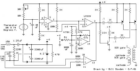
Electronic Thermostat and Relay Circuit
Published:2012/10/22 1:30:00 Author:muriel | Keyword: Electronic Thermostat, Relay Circuit
Here is a simple thermostat circuit that can be used to control a relay and supply power to a small space heater through the relay contacts. The relay contacts should be rated above the current requirements for the heater. Temperature changes are detected by a (1.7K @ 70F) thermistor placed in series with a 5K potentiometer which produces about 50 millivolts per degree F at the input of the LM339 voltage comparator. The two 1K resistors connected to pin 7 set the reference voltage at half the supply voltage and the hysteresis range to about 3 degrees or 150 millivolts. The hysteresis range (temperature range where the relay engages and disengages) can be adjusted with the 10K resistor between pins 1 and 7. A higher value will narrow the range. In operation, the series resistor is adjusted so that the relay just toggles off at the desired temperature. A three degree drop in temperature should cause the relay to toggle back on and remain on until the temperature again rises to the preset level. The relay action can be reversed so it toggles off at the lower end of the range by reversing the locations of the 5K potentiometer and thermistor. The 5.1 volt zener diode regulates the circuit voltage so that small changes in the 12 volt supply will not effect operation. The voltage across the thermistor should be half the supply or about 2.6 volts when the temperature is within the 3 degree range set by the potentiometer. Most any thermistor can be used, but the resistance should be above 1K ohm at the temperature of interest. The series resistor selected should be about twice the resistance of the thermistor so the adjustment ends up near the center of the control. (View)
View full Circuit Diagram | Comments | Reading(1186)
9 Second Digital Readout Countdown Timer
Published:2012/10/22 1:29:00 Author:muriel | Keyword: 9 Second, Digital Readout Countdown, Timer
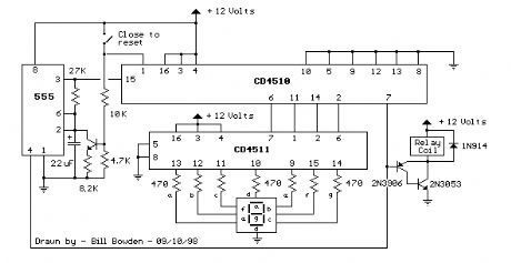
This circuit provides a visual 9 second delay using a 7 segment digital readout LED. When the switch is closed, the CD4010 up/down counter is preset to 9 and the 555 timer is disabled with the output held high. When the switch is opened, the timer produces an approximate 1 second clock signal, decrementing the counter until the 0 count is reached. When the zero count is reached, the 'carry out' signal at pin 7 of the counter moves low, energizing the 12 volt relay and stopping the clock with a low signal on the reset line (pin 4). The relay will remain energized until the switch is again closed, resetting the counter to 9. The 1 second clock signal from the 555 timer can be adjusted slightly longer or shorter by increasing or decreasing the resistor value at pin 3 of the timer.
The CD4510 is a CMOS Presettable BCD Up/Down counter which can be preset to any number between 0 and 9 with a high level on the PRESET ENABLE line, (pin 1) or reset to 0 with a high level on the RESET line (pin 9). Inputs for presetting the counter (P1, P2, P3, P4) are on pins (4, 12, 13, 3) respectively. The counter advances up or down on each positive-going clock transition (pin 15) and the counting direction (up or down) is controlled by the logic level on the UP/DOWN input (pin 10, high=up, low=down). The CARRY-IN signal (pin 5) disables the counter with a high logic level. (View)
View full Circuit Diagram | Comments | Reading(2802)
9 Second LED Timer and Relay Circuit
Published:2012/10/22 1:28:00 Author:muriel | Keyword: 9 Second , LED Timer, Relay Circuit
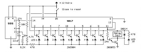
This circuit provides a visual 9 second delay using 10 LEDs before closing a 12 volt relay. When the reset switch is closed, the 4017 decade counter will be reset to the 0 count which illuminates the LED driven from pin 3. The 555 timer output at pin 3 will be high and the voltage at pins 6 and 2 of the timer will be a little less than the lower trigger point, or about 3 volts. When the switch is opened, the transistor in parallel with the timing capacitor (22uF) is shut off allowing the capacitor to begin charging and the 555 timer circuit to produce an approximate 1 second clock signal to the decade counter. The counter advances on each positive going change at pin 14 and is enabled with pin 13 terminated low. When the 9th count is reached, pin 11 and 13 will be high, stopping the counter and energizing the relay. Longer delay times can be obtained with a larger capacitor or larger resistor at pins 2 and 6 of the 555 timer. (View)
View full Circuit Diagram | Comments | Reading(1799)
Power-Off Time Delay Relay
Published:2012/10/22 1:28:00 Author:muriel | Keyword: Power-Off Time, Delay Relay
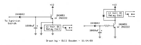
The two circuits below illustrate opening a relay contact a short time after the ignition or ligh switch is turned off. The capacitor is charged and the relay is closed when the voltage at the diode anode rises to +12 volts. The circuit on the left is a common collector or emitter follower and has the advantage of one less part since a resistor is not needed in series with the transistor base. However the voltage across the relay coil will be two diode drops less than the supply voltage, or about 11 volts for a 12.5 volt input. The common emitter configuration on the right offers the advantage of the full supply voltage across the load for most of the delay time, which makes the relay pull-in and drop-out voltages less of a concern but requires an extra resistor in series with transistor base. The common emitter (circuit on the right) is the better circuit since the series base resistor can be selected to obtain the desired delay time whereas the capacitor must be selected for the common collector (or an additional resistor used in parallel with the capacitor). The time delay for the common emitter will be approximately 3 time constants or 3*R*C. The capacitor/resistor values can be worked out from the relay coil current and transistor gain. For example a 120 ohm relay coil will draw 100 mA at 12 volts and assumming a transistor gain of 30, the base current will be 100/30 = 3 mA. The voltage across the resistor will be the supply voltage minus two diode drops or 12-1.4 = 10.6. The resistor value will be the voltage/current = 10.6/0.003 = 3533 or about 3.6K. The capacitor value for a 15 second delay will be 15/3R = 1327 uF. We can use a standard 1000 uF capacitor and increase the resistor proportionally to get 15 seconds. (View)
View full Circuit Diagram | Comments | Reading(1464)
Power-On Time Delay Relay
Published:2012/10/22 1:27:00 Author:muriel | Keyword: Power-On Time, Delay Relay
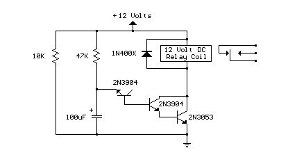
Here's a power-on time delay relay circuit that takes advantage of the emitter/base breakdown voltage of an ordinary bi-polar transistor. The reverse connected emitter/base junction of a 2N3904 transistor is used as an 8 volt zener diode which creates a higher turn-on voltage for the Darlington connected transistor pair. Most any bi-polar transistor may be used, but the zener voltage will vary from about 6 to 9 volts depending on the particular transistor used. Time delay is roughly 7 seconds using a 47K resistor and 100uF capacitor and can be reduced by reducing the R or C values. Longer delays can be obtained with a larger capacitor, the timing resistor probably shouldn't be increased past 47K. The circuit should work with most any 12 volt DC relay that has a coil resistance of 75 ohms or more. The 10K resistor connected across the supply provides a discharge path for the capacitor when power is turned off and is not needed if the power supply already has a bleeder resistor. (View)
View full Circuit Diagram | Comments | Reading(3525)
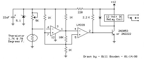
Low Voltage, High Current Time Delay Circuit
Published:2012/10/22 1:26:00 Author:muriel | Keyword: Low Voltage, High Current , Time Delay Circuit
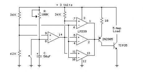
In this circuit a LM339 quad voltage comparator is used to generate a time delay and control a high current output at low voltage. Approximatey 5 amps of current can be obtained using a couple fresh alkaline D batteries. Three of the comparators are wired in parallel to drive a medium power PNP transistor (2N2905 or similar) which in turn drives a high current NPN transistor (TIP35 or similar). The 4th comparator is used to generate a time delay after the normally closed switch is opened. Two resistors (36K and 62K) are used as a voltage divider which applies about two-thirds of the battery voltage to the (+) comparator input, or about 2 volts. The delay time after the switch is opened will be around one time constant using a 50uF capacitor and 100K variable resistor, or about (50u * 100K) = 5 seconds. The time can be reduced by adjusting the resistor to a lower value or using a smaller capacitor. Longer times can be obtained with a larger resistor or capacitor. To operate the circuit on higher voltages, the 10 ohm resistor should be increased proportionally, (4.5 volts = 15 ohms). (View)
View full Circuit Diagram | Comments | Reading(970)
Clock Timer Circuit
Published:2012/10/22 1:22:00 Author:muriel | Keyword: Clock Timer
View full Circuit Diagram | Comments | Reading(904)
Digital Clock with Timer and Solar Panel Regulator
Published:2012/10/22 1:21:00 Author:muriel | Keyword: Digital Clock, Timer, Solar Panel Regulator
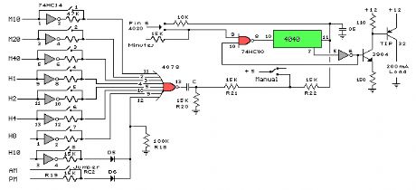
This is a combination digital clock timer and solar panel charge controller used to maintain a deep cycle battery from a solar panel. The timer output is used to control a 12 volt load for a 32 minute time interval each day. Start time is set using 9 dip switches and ends 32 minutes later. The 32 minute duration is set by selecting the 5th bit (2^5 = 32) of a 4040 binary counter (pin 2). The timer also has a manual toggle switch so the load can be manually switched on or off and automatically shuts off after 32 minutes. The time duration can be longer or shorter (8,16,32,64,128,256 minutes etc.) by selecting the appropriate bit of the counter. The timer circuit is shown in the lower schematic just above the regulator.
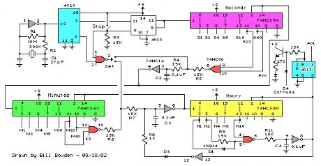
The basic clock circuit (top schematic below) is similar to the binary clock (on another page) and uses 7 ICs to produce the 20 digital bits for 12 hour time, plus AM and PM. A standard watch crystal oscillator (32,768) is used as the time base and is divided down to 1/2 half second by the 4020 binary counter. One half of a 4013 data latch is used to divide the 1/2 second signal by 2 and produce a one second pulse that drives the seconds counter (74HC390 colored purple). The minutes are advanced by decoding 60 seconds (40 + 20) and then resetting the seconds counter to 0 and at the same time advancing the minutes counter. The same procedure is used to advance the hours. The second half of the 4013 latch is used to indicate AM or PM and is toggled by decoding 13 hours and resetting the hours to 0 and then advancing the hours to one . (View)
View full Circuit Diagram | Comments | Reading(2205)
Binary Coded Decimal (BCD) Clock
Published:2012/10/22 1:20:00 Author:muriel | Keyword: Binary Coded Decimal (BCD), Clock
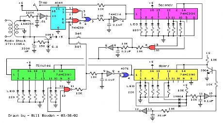
The clock circuit above uses seven ICs and 19 LEDs to indicate binary coded decimal time. The LEDs can be arranged (as shown in example above) so that each horizontal group of 3 or 4 LEDs represents a decimal digit between 0 and 9 and each individual LED represents a single bit or (binary digit) of the value. Binary digits have only two values (0 and 1) so a number written in binary would be something like 1001 or 0011, which represents decimal numbers 9 and 3 respectively. From right to left, each binary (1) represents increasing powers of 2, so that a 1 in the right hand place represents 2^0=1 and the next place to the left is 2^1=2 and then 2^2=4, and so forth. This makes binary counting fairly easy since each digit has a value of twice the one before or 1,2,4,8,16,32,64,etc. Thus the decimal value can be found by simply adding the values of each illuminated LED in the same row, (the total is shown in the box to the right). For example, the binary number 1001 would have a decimal value of 8+0+0+1 = 9. But this is actually a binary coded decimal 9 since only values from 0 to 9 are used 0000 to 1001. A true binary clock indicating minutes of the hour would display values from 0 to 59, or 000000 to 111011. But this would be more difficult to read since adding values 32 + 16 + 8 + 2 + 1 = 59 is not as easy as 8 + 0 + 0 + 1 = 9.
The circuit is powered by a small 12.6 VAC transformer which also provides a low voltage 60 Hz signal for a very accurate time base. The transformer is connected with the secondary center tap at ground which produces about 8 volts DC across the 3300uF filter capacitor. DC power for the circuit is regulated at about 5.5 using a NPN transistor (2N3053) and 6.2 volt zener diode. The 2N3053 gets a little warm when several LEDs are on, and may require a little (top hat type) heat sink. (View)
View full Circuit Diagram | Comments | Reading(1846)
| Pages:53/312 At 204142434445464748495051525354555657585960Under 20 |
Circuit Categories
power supply circuit
Amplifier Circuit
Basic Circuit
LED and Light Circuit
Sensor Circuit
Signal Processing
Electrical Equipment Circuit
Control Circuit
Remote Control Circuit
A/D-D/A Converter Circuit
Audio Circuit
Measuring and Test Circuit
Communication Circuit
Computer-Related Circuit
555 Circuit
Automotive Circuit
Repairing Circuit