
Control Circuit
Index 56
Traffic Alert Project
Published:2012/10/8 2:43:00 Author:muriel | Keyword: Traffic, Alert Project
This Solar based LED flasher can Alert vehicles in heavy traffic areas or places where road work is going on. It is fully automatic and turns on in the evening. During day time it remains off and charge the battery using solar energy.The circuit has two sections. A battery charger and a Flasher circuit. The battery charger uses 6 volt solar panel to convert light energy into electrical energy. During day time, the fully illuminated solar panel provides 6 volts DC through diode D1 to charge battery. When current flows through D1, base of the PNP Darlington transistor T1 remains positive to keep it off. So the flasher section will not get current and it remains off. When the light falling on the solar panel reduces, current flow through D1 ceases and it reverse biases. T1 then conducts as its base becomes negative. This provides current to the flasher circuit.
Flasher circuit is built around the popular binary counter IC HEF4060. A CMOS version is used to reduce the power consumption. When the IC gets battery power supply from the collector of T1, it resets through C1 and R2 and starts oscillations using R4 and C2. Out put pulses will be available from the Q3 output (pin7) causing T2 to turn on/off alternately. This makes the LED string flashing.
Modifications
The circuit is designed for six LEDs using a miniature 4.8 volt rechargeable battery. If more LEDs are required, increase the value of solar panel to 12 volts and the capacity of battery to 6 volt 4.5Ah. Use High bright transparent yellow LEDs for more visibility. For portable use, fix a switch in the battery positive.
Traffic Alert Circuit diagram
IC HEF4060
(View)
View full Circuit Diagram | Comments | Reading(760)
Display Driver circuit
Published:2012/10/8 2:35:00 Author:muriel | Keyword: Display Driver
This display driver circuit shows how a Seven Segment Display is driving with the help of the 5 stage Johnson decade counter IC CD4033.The IC has counter and decoder in one package. It converts the Johnson codes into Seven Segment Decoder output to drive the common cathode display. The display shows the counts in the form of numerical display. The display driver circuit is powered from a 9 volt DC supply and the outputs of IC are connected to the Common Cathode Seven Segment display LT 543. The IC counts continuously up to 9 if the Clock Enable, Strobe and Reset pins are grounded. The cycle repeats till the Reset pin gets a High pulse. The input of CD 4033 is a sensitive Schmitt trigger and readily accepts positive to negative transition pulses to starts the counting.
The counter advances and the signals are available at the outputs as decoded signals which can drive the numerical display. CD 4033 can be Cascaded to connect many displays to count 100, 1000 etc. If the Carry Out pin 5 of one IC is connected to the Clock Input pin 1 of the second IC, counter continues and the second IC starts counting when the first IC completes 9 counts. In such a way many ICs can be cascaded.
Display Driver Circuit diagram
CD4033 Datasheet
CD4033 Cascading circuit
Seven Segment Display – Common Cathode
(View)
View full Circuit Diagram | Comments | Reading(827)
Servo Motor Controller
Published:2012/10/8 2:34:00 Author:muriel | Keyword: Servo Motor, Controller
This is the simple basic design of Servo pulse generator. It uses the CMOS IC 7555 in the Astable mode to generate pulses to drive the servo motor. The circuit can be suitably modified to get pulses of sufficient length.A Servo is a small device that has an output shaft. This shaft can be positioned to specific angular positions by sending the servo a coded signal. As long as the coded signal exists on the input line, the servo will maintain the angular position of the shaft. The angular position of the shaft is determined by the duration of a pulse that is applied to the control wire. This is called Pulse Coded Modulation.
The servo typically requires pulse every 20 milliseconds (.02 seconds). The length of the pulse will determine how far the motor turns. Generally, 1.5 millisecond pulse will make the motor turn to the 90 degree position. This is called the Neutral Position. If the pulse is shorter than 1.5 ms, the motor will turn the shaft to close to 0 degrees. If the pulse is longer than 1.5ms, the shaft turns closer to 180 degrees.
Servo Motor Controller Circuit diagram
The circuit is designed to give control signals to the Servo.IC1 is designed as an Astable multi vibrator which can give pulses for the operation of the Servo. The 10KPot VR2, R1 and capacitor C1 determines the High and Low time of pulses. Since VR2 is variable, High time varies from 2.07 mS to 1.03 mS. The low time will be 40.5 mS. By adjusting VR1, it is easy to get exact timing.VR3 adjust the control voltage of 1.6 volts to the control pin 5 of IC1.
Servo Motor
A control voltage can also be supplied from outside. Then VR3 should be omitted. The control volt can be provided from a variable power supply that gives output of 0-10 volts. The control voltage will control the position of the servo motor connected to the output. When the control voltage changes, the servo will move to the new position corresponding to the new control voltage value. 0 volt causes the servo to remain at one end and 10 volts to other end. If the control volt is 5 volts the servo remains in the center position. (View)
View full Circuit Diagram | Comments | Reading(1784)
The high power control circuit with 3 different driving ways
Published:2012/9/28 22:51:00 Author:Ecco | Keyword: high power, control circuit, 3 , different driving ways
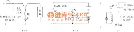
Flashing light-emitting diode can be used as the core component of high-power multi- load control circuit to drive various incandescent flashing lights. Figure (a) shows a high - power transistor driving circuit; Figure (b) shows a bidirectional thyristor-controlled with high-power drive circuit ; The circuit shown in Figure (C) uses a relay to control load. VT can use 3AD, 3CD high power PNP transistor. Transistor can also use one - way , but the load current is the pulsating DC current. The loads of 3 kinds of circuits can intermittently work under the control of flashing light-emitting diode.
(View)
View full Circuit Diagram | Comments | Reading(1081)
Motion detector alarm circuit
Published:2012/9/28 21:02:00 Author:muriel | Keyword: Motion detector, alarm
This motion detector alarm circuit can detect a moving person from a distance of 1 meter. It uses a Dual IR Transmitter-Receiver module HOA1405. When the sensor detects the reflected IR rays, Alarm will sound for 2 minutes. The circuit can be modified for various applications including AC operated alarm systems.
Motion Detector Circuit Schematic
The main element in the motion detector circuit is the Dual IR reflective sensor HOA 1405. It has a built in IR diode and an NPN Photo transistor. The black covering of the module filters visible light rays and allow IR rays to fall on the Photo transistor. When the Photo transistor receives IR rays, it conducts. The collector of the Photo transistor is connected to the trigger pin2 of a short duration Monostable timer built around IC NE 555.
With the given values of R4 and C2, output of IC1 remains high for two minutes to light LED and to activate the buzzer. In the standby state, the photo transistor inside the Dual Reflector module remains non conducting since its base is not getting IR rays. When a person comes in front of the module, the reflected IR rays will trigger the Photo transistor and its Collector goes to ground potential. This triggers the Monostable and Alarm sounds.
IR Dual Reflective Sensors
(View)
View full Circuit Diagram | Comments | Reading(1559)
Three State Voltage Indicator circuit
Published:2012/9/28 21:02:00 Author:muriel | Keyword: Three State, Voltage Indicator
This is an ideal circuit to monitor the Voltage level in 12 volt Lead Acid batteries used in Inverters .For the perfect operation of Inverters, the battery voltage should be between 12 and 13.5 volts. A fully charged battery shows 13.5 volts. If the voltage reduces below 10 volts, the Inverter will not give back up. Moreover, if the Inverter is continuously charging without attaining 13.5 volts, it indicates that the battery is not accepting and holding charge.The circuit is too simple and uses only a few components. It shows three indications.
1. If the battery has 13.5 volts, Green half of the bicolor LED lights.2. If the battery has 12 volts(Normal) LED will be Off3. If the battery voltage reduces below 10 volts, Red half of bicolour LED lights.
About the Semiconductors
The important components of the circuit are a two lead type bicolour LED and the Operational Amplifier CA3140.
Bicolour LED
The Bicolour LED used in the circuit is a Two Lead type. That is, it can give Red or Green lights based on the polarity of the leads. If the leads are connected in one direction, it gives one colour and if the leads are reversed, it gives the second colour. Thus there is no Anode- Cathode arrangement. Both the leads can function as Anode and Cathode. The internal arrangement of the LED automatically changes the direction of current based on the polarity. Here the LED used gives Red and Green colours.
BIcolour LED Datasheet
CA3140This Operational Amplifier is a 4.5 MHz BiMOS Op Amp with gate protected MOSFET inputs and Bipolar output. Its inputs have very high input impedance (1.5T Ohms).It require very low input current (10pA) and hasvery high speed of performance. The IC can operate between 4 – 36 volts with single or dual power supply.CA3140 is internally phase compensated for stable operation
(View)
View full Circuit Diagram | Comments | Reading(884)
Battery Guard for Emergency Lights
Published:2012/9/28 21:01:00 Author:muriel | Keyword: Battery Guard, Emergency Lights
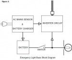
As the name implies,emergency light is a source of light available during an emergency.It is an automatic system in which a rechargeable battery operated light source turns on as soon as the ac mains fail.When the grid supply is restored,the lamp is turned off. An emergency light essentially consists of a source of electricity – a rechargeable battery pack and an automatic sensing circuit to check the presence(or absence) of mains supply.The sensing circuit connects a lamp (or a compact fluorescent tube inverter) circuit in the event of mains failure and disconnects it when the mains supply is restored.When ac mains supply is available,a charger circuit charges the battery pack to keep it in top condition(fig 2).
Emergency Lights Guard Circuit Diagram
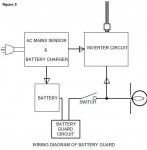
Over the years,emergency lights have become better designed and more reliable. However, they retain a few weak facilities. Usually 6 volt sealed maintenance free (SMF) batteries are used in portable emergency lights. Unfortunately, many low cost lights give no indication when the battery has gone flat, so that there is a risk of the battery failure. Only high-end systems have built in electronic deep discharge protection circuitry to disconnect the output load in case the battery voltage happens to fall below a safe value.
(View)
View full Circuit Diagram | Comments | Reading(1846)
Smart smoke sensor alarm circuit
Published:2012/9/28 20:59:00 Author:muriel | Keyword: Smart smoke, sensor, alarm
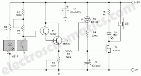
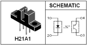
At the heart of this ultra simple smoke sensor or detector alarm is H21A1, which is a photo-interrupter module consists of a gallium-arsenide infrared LED coupled to a silicon phototransistor in a plastic housing. The slot between the infrared sender(LED) and receiver (phototransistor) allows interruption of the signal with smoke, switching the module output from ‘on’ to ‘off’.When the smoke enters the slot, the infrared beam falling on the phototransistor is obstructed. As a result, the phototransistor stops working and the transistors (T1&T2), wired as a simple darlington pair, conduct to activate the rest of the circuit.
When the darlington pair conducts, the gate voltage of SCR BT169 (T3) goes high and the SCR is fired. Consequently, the gate terminal of mosfet BS170 (T4) receives positive voltage through resistor R4 and the active piezo-sounder (BZ1) energises to latch! Visual indicator LED (D1) lights up instantly. The buzzer sounds to indicate the presence of smoke, unless you switch off the circuit by disconnecting the 9 volt dc input supply. For optimum performance, adjust trimpots P1, P2 and the value of resistor R1.
Smoke detector alarm circuit diagram
H21A1 schematic
(View)
View full Circuit Diagram | Comments | Reading(3303)
Entry Alarm circuit
Published:2012/9/28 20:58:00 Author:muriel | Keyword: Entry, Alarm circuit
This is an Infrared based Brocken beam alarm to protect doors and entry passages. It gives a loud alarm when somebody crosses the Invisible Infrared barrier. It can protect the doors both day and night and is free from false triggering. The circuit is too simple and can be a good evening project for the hobbyists. The circuit uses Infrared diodes to emit continuous IR rays which are not pulsed as in the case of remote handsets. The NPN Darlington Photo transistor is used as a light sensor. L14F1 is the ultra sensitive Darlington photo transistor with high gain. Its collector is connected to the positive rail through VR1 and the Emitter has a Green LED to indicate standby mode. The base of T1 is left free without connecting anywhere. This base junction is exposed through the window of T1 so that light photons will bias the base.
The degree of biasing depends on the intensity of photons.T2 is the alarm driver and its base is connected to the collector of T1.So that the base bias of T2 depends on the conduction of T1. When the Infrared rays illuminate the photo transistor, it conducts pulling the base of T1 to ground level so that it remains off. Red LED and Buzzer connected to the emitter of T2 remains off in this condition. When a person crosses the IR beam, T1 turns off and its collector voltage becomes high. T2 then conducts and activates Red LED and buzzer.L14F1 DatasheetBC547 Datasheet
Entry Alarm Circuit diagram
The circuit can be constructed on a small piece of Perf board. Assemble R1 and IR LEDs on a separate board. Fix IR LEDs on one side of the entry and the Phototransistor on the opposite side. Carefully align IR beam on the Phototransistor so that buzzer will be silent in the standby mode. Move hand across the beam, buzzer should sound.VR1 adjust the base bias of T2 to keep the buzzer off in the standby mode.
L14F1 Phototransitor
L14F1 and BC547 Pins
(View)
View full Circuit Diagram | Comments | Reading(1048)
Timer light switch circuit
Published:2012/9/28 20:57:00 Author:muriel | Keyword: Timer, light, switch
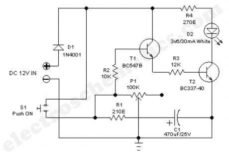
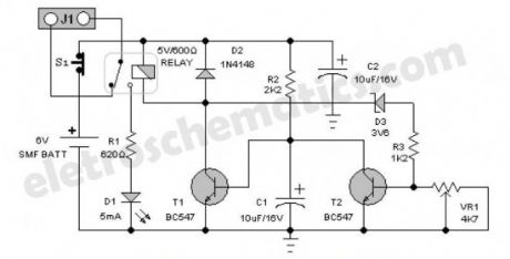
Tiny Timer Light Switch presented here is a simple transistorised electronic timer which drives a high efficiency white LED for a finite time out. This circuit is very useful for in-car reading etc. The circuit works off 12 volt dc supply. After construction, fit the unit at a suitable location inside your car and power the circuit from the in-dash standard cigar lighter socket. The timer light switch is ultra simple, economic, straight forward and self explanatory. How the timer light switch works?Normally T1 is turned off by P1 and R2. When the trigger switch S1 is pressed the base of T1 is connected to the +12V supply via R2. Now T1 turns on and this action turns on the next transistor T2 which in turn energises the white LED (D2). Resistor R4 limits the operating current of white LED (D2).
When the switch is pressed is current also flows into capacitor C1 (through R1) and charges it. So when the switch S1 is released the charge in the capacitor C1 keeps T1 turned on until the charge has decayed away through R2 and P1. You can easily increase the ouput on time by increasing the resistance of the potentiometer P1.
Timer Light Switch Circuit Diagram
(View)
View full Circuit Diagram | Comments | Reading(1978)
Short Circuit Indicator
Published:2012/9/28 20:57:00 Author:muriel | Keyword: Short Circuit, Indicator
Here is a valuable Add on circuit to save electronic components in the assembled board from damage. It gives warning beep if there is a short circuit in the assembled board. Thus it helps to switch off the power supply immediately to save valuable components. If the circuit board is OK, Green LED lights indicating that power supply is normal. If there is a short in the PCB tracks or pins of components, Green LED turns off and Buzzer sounds indicating the short circuit. The circuit uses two NPN transistors BC 547 to sense the short circuit. If the assembled board is normal, current flows from the power supply through polarity protecting diode D1. The Assembled board gets power and Green LED lights. At the same time T2 forward bias and its collector goes to ground potential. This makes T1 off due the absence of base bias. Buzzer and Red LED connected to the collector of T1 remains off. If there is a short circuit in the board under test, D2 reverse biases and T2 turns off. Now the base of T1 becomes high and it conducts. This turns on Buzzer and Red LED to indicate short circuit.
Short Circuit Indicator Circuit diagram
Connect the circuit to the output of the Power supply observing polarity.Output of the circuit is used to power the circuit board under test. (View)
View full Circuit Diagram | Comments | Reading(842)
Multiplexer Switch circuit with 4066
Published:2012/9/28 20:56:00 Author:muriel | Keyword: Multiplexer, Switch circuit,4066

This multiplexer switch circuit is built with the IC 4066 and was designed to switch multiple signal sources into a single common output and can be used as a replacement for the conventional mechanical switches.Conventional multiplexer switches hava an annoying disadvantage that the video signals mix over when the source is changed but this circuit avoids this problem by disabling the inactive signal line.The heart of the switch is a digitally controlled analog switch 4066. The switches are ES1 … ES8 and each 4066 contains 4 switches. When channel 1 is selected, ES1 and ES2 are closed and ES3 is open. Channel is suppressed at this moment since ES5 and ES6 are open and ES7 prevents cross-over between the two channels by grounding the channel 2 line.
The bandwidth of the multiplexer sw circuit is around 8 MHz. The current consumption is 1 mA. A high level power supply voltage level is required since the input impedance level of the circuit drops with higher voltage levels.
When the multiplexer circuit is connected to a 75 Ω impedance load, some signal losses will result due to the internal resistance of the switches. This can be compensated by connecting a video amplifier at the output.Article submitted by Michael Gregory – Romania.
Multiplexer Switch Circuit Diagram
(View)
View full Circuit Diagram | Comments | Reading(2526)
Infrared Switch circuit
Published:2012/9/28 20:50:00 Author:muriel | Keyword: Infrared, Switch
Here is a Simple Infrared controlled Switch. It can be operated using the TV remote handset.The Load can be any AC operated device which can be connected to the relay. The load turns on for three minutes then goes off. It can be used to switch on the lamp in the TV roomThe circuit uses the popular IR sensor module TSOP 1738 and the precision Monostable / Astable IC CD4538. TSOP 1738 IR sensor accepts 38 KHz infrared pulses from the remote. Its output is high at power on and gives 5 volts. When it senses pulsed IR rays, its output becomes low.
IR Switch Circuit diagram
CD4538 is the Precision Monostable /Astable Multivibrator IC that is free from false triggering. It is more reliable than the popular timer IC 555. Here the IC1 is wired as a short duration monostable timer using R3 and C1 as timing components. With the given values, output of IC1 remains low for three minutes. By changing the value of C1 or R3 various time intervals can be obtained. Unlike 555 IC in the monostable mode, here in CD4530, output of IC becomes high at power on and becomes low when the trigger pin5 gets a low-to-high transition pulse. (View)
View full Circuit Diagram | Comments | Reading(1060)
Telephone Guard circuit
Published:2012/9/28 20:46:00 Author:muriel | Keyword: Telephone Guard

Here is a simple circuit to protect your Telephone, EPBAX, Telephone Modem etc from lightning discharge or line spikes. It uses a safety capacitor and Gas Tube Arrester to prevent damage of the devices
The circuit is too simple but its use is great. The main elements of the circuit are a Gas Discharge Tube (GDT) and a safety capacitor.
Gas Discharge Tube
The GDT used in the circuit is NS2R – 230 A1 – N make 2 pole Arrester. It is a 2 electrode Ceramic Gas Tube Arrester rated 5KA / 5A. GDT is a surge protection device do the same job as an MOV. GDT divert the extra current from the hot line to the ground line using an inert gas as the conductor between the two lines.
When the voltage is at a certain level, the gas inside the GDT remains non conducting. When the voltage surges above that level occurs, the electrical power is strong enough to ionize the gas, making the gas a very effective conductor. It then passes current to the ground line until the voltage reaches normal level. Then again GDT becomes a poor conductor.
2 Electrode GDT
Safety Capacitor
Safety Capacitors are designed to withstand high impulse voltages in applications where human beings might be exposed to voltage surges. These capacitors will shunt the energy from the impulse to ground, protecting the circuit from the surge. Safety capacitors are available in ceramic disc and metalized film or paper. The film type are made of self-healing metalized polyester, polypropylene or paper and usually come in a “box” style casing as the capacitor is encased is a flame retardant or flame-proof case. The safety capacitor used in the circuit is 220 K 250Volt DC
220K 250 V DC Capacitor
The circuit is self explanatory and easy to make on a piece of Perf board.You can also do lead-to-lead soldering. Enclose the circuit in a small box and connect to the telephones lines and phone / modem as shown in the diagram.
Telephone Guard Circuit Diagram
(View)
View full Circuit Diagram | Comments | Reading(872)
Atmospheric Charge Monitor circuit
Published:2012/9/27 21:41:00 Author:muriel | Keyword: Atmospheric, Charge Monitor
This circuit is designed to monitor the atmospheric charge. By observing the increase in the atmospheric charge, it is possible to predict a nearby lightning. The sudden electric discharge during a lightning may cause the flow of excessive current to earth which may be detrimental to the appliances connected to mains lines.Normal atmospheric charge on a sunny day will be around 100 milli volts with negligible current and may increase to many volts as the clouds accumulate in the sky. This may go up to thousands of volts before the lightning strikes. The circuit described here monitors the atmospheric condition and display the same through LED indications.
The front end of the Atmospheric Charge circuit has a Op Amp comparator built around IC TL071. It is a JFET input op amp with an open loop voltage gain of 100dB.Its inverting input is connected to the positive rail through two presets VR1 and VR2 while the non inverting input is connected to the antenna. Resistor R2 protects the input of IC from excessive charge while R1 keeps the non inverting input stable. TL071 has very high gain, so R3 is provided to give some negative feedback.
Output from IC1 is around 2.5 to 5 volts which passes to the input pin5 of IC2 through VR3. Resistor R4 protects VR3 if its wiper is turned fully. IC2 LM3914 is a monolithic integrated circuit< that can sense analogue voltage levels to drive the LEDs and provide a linear analogue display. Current through the LEDs is self regulated by the IC eliminating the need of current limiting LED resistors. Its low bias current input pin5 receives signals down to 0.5 volts and its outputs 18 to 10 sinks current one by one as its input receives an increment of 125 milli volts. The LEDs can give a DOT mode display if pin 9 of IC2 is unconnected. If it is connected to positive rail, bar mode display can be obtained.D1 lights when the input pin 5 gets 1.7 volts andD5 light up when the input gets 4.2 volts.
Atmospheric Charge Monitor Circuit diagram
Adjustments
Before applying power to the circuit, turn the wiper of VR1 to the extreme anti clock position and keep the wiper of VR3 in the middle position. When the wiper of VR2 turns to clock wise direction, D2 to D5 light up one by one. Adjust VR3 till D4 turns on. Wait for some time and see that D5 is glowing. This shows that the circuit is responding to changes in atmospheric charge. It is necessary to make adjustments on a sunny day with clear sky. Adjust VR2 till D1 glows. This indicates normal atmospheric charge. As the charge in the atmosphere increases due to the accumulation of clouds, D2 through D5 lights.
Antenna can be 3 meters plastic wire. The negative rail of the circuit should be earth grounded since the circuit is monitoring the atmospheric potential with reference to ground. Earth grounding can be done by piling an iron rod into the earth. Connect the circuits negative to this iron rod. Keep the unit inside the room near the window. Do not try adjustments if there is lighting. (View)
View full Circuit Diagram | Comments | Reading(1082)
Power Supply Guard circuit
Published:2012/9/27 21:37:00 Author:muriel | Keyword: Power Supply, Guard
Here is a Power Supply Guard circuit that can be used as a protective device in power supply boxes. This type of Spike protection circuit is present in the multi socket switch boards used to connect computer peripherals. This circuit is useful to guard the electronic or electrical devices from mains transients and spikes. If heavy transients develop in the mains, the MOV in the circuit short circuit the lines and the fuse will blow out.
The Power Supply Guard circuit uses a Metal Oxide Varistor 431KD14, a 0.1 uF X2 rated AC capacitor, a Toroidal transformer and two 2KV disc capacitors.Components:
Metal Oxide Varistor
Metal Oxide Varistor (MOV) contains a ceramic mass of zinc oxide grains, in a matrix of other metal oxides such as small amounts of bismuth, cobalt, manganese etc. sandwiched between two metal plates which forms the electrodes. The boundary between each grain and its neighbour forms a diode junction, which allows current to flow in only one direction. When a small or moderate voltage is applied across the electrodes, only a tiny current flows, caused by reverse leakage through the diode junctions. When a large voltage is applied, the diode junction breaks down due to a combination of thermionic emission and electron tunneling, and large current flows. Varistors can absorb part of a surge.The effect depends on the equipment and details of the selected varistor.
MOV
A varistor remains non-conductive as a shunt mode device during normal operation when voltage remains well below its “clamping voltage”. If a transient pulse is too high, the device may melt, burn, vaporize, or otherwise be damaged or destroyed.
Toroidal TransformerToroidal transformers are built around a ring-shaped core. The primary and secondary coils are often wound concentrically to cover the entire surface of the core. This minimizes the length of wire needed, and also provides screening to minimize the core’s magnetic field from generating electromagnetic interference. In the circuit, the toroidal transformer is made using primary and secondary winding each having 20 turns of 22 SWG enameled copper wire. The core can be procured from the damaged power supply boards of UPS or SMPS.
Power Supply Guard Circuit
Toroidal transformer
Toroid Core
2 KV Capacitor 0.1 uF X rated AC Cap 250 volt
Power supply Guard – Assembled Board
(View)
View full Circuit Diagram | Comments | Reading(980)
LED VoltMeter circuit
Published:2012/9/27 21:36:00 Author:muriel | Keyword: LED, VoltMeter
Here is a Simple LED Voltmeter to Monitor the charge level in Lead Acid Battery or Tubular battery. The terminal voltage of the battery is indicated through a four level LED indicators.The nominal terminal voltage of a Lead Acid battery is 13.8 volts and that of a Tubular battery is 14.8 volts when fully charged. The LED voltmeter uses four Zener diodes to light the LEDs at the precise breakdown voltage of the Zener diodes. Usually the Zener diode requires 1.6 volts in excess than its prescribed value to reach the breakdown threshold level. When the battery holds 13.6 volts or more, all the Zener breakdown and all LEDs light up. When the battery is discharged below 10.6 volts, all the LEDs remain dark. So depending on the terminal voltage of the battery, LEDs light up one by one or turns off.
LED VoltMeter Circuit Schematic
(View)
View full Circuit Diagram | Comments | Reading(968)
Battery Self discharge Indicator
Published:2012/9/27 21:36:00 Author:muriel | Keyword: Battery, Self discharge, Indicator
If the lead acid battery is not using for long time, self discharge takes place at the rate of 4 % per week at 27 degree. For example, a 125 Ah tubular battery self discharge at the rate of 5 Amps current per week if it is not in charge / discharge cycles. This add on circuit can be used to detect the self discharge of the 12 volt lead acid battery below the safe level of 11.6 volts. It is ideal to monitor the charge level in the battery, it the battery is not using for long period.The Battery Self discharge Indicator circuit uses only a few components and its working is simple. A PNP transistor T1 act as a switch to light the LED, if the battery voltage drops below the safe level. The base bias of T1 is controlled by a Zener diode ZD. Its rating is 10 volt 1 W. The Zener diodes usually requires 1.6 volts excess than its rated value to enter into the “Avalanche state”.
Battery Self discharge Indicator Circuit
So, as long as the battery voltage is above 11.6 (10+1.6), Zener conducts and keeps the base of T1 high. Since T1 is a PNP transistor, it will not conduct till its base becomes negative. So LED remains dark. When the voltage in the battery reduces below 11 volts, Zener turns off and the base of T1 becomes negative. T1 then conducts and LED lights. So the battery can be charged again to keep it in top condition. Preset VR can be used to set the exact point at which LED turns on. (View)
View full Circuit Diagram | Comments | Reading(906)
Heatsink temperature monitor circuit
Published:2012/9/27 21:33:00 Author:muriel | Keyword: Heatsink, temperature monitor

This heatsink temperature monitor circuit signals via 3 LEDs when the temperature exceeds 2 boundary levels. When the heatsink temperature is below 50 … 60oC (122 … 140oF) the greed LED lights. The yellow one signals that the temperature is within 60 and 70oC (140 … 158oF). The red one signals that the temperature has reached beyond 70 … 80o (158 … 176oF). At this point a relay can be triggered to break the power supply or otherwise protect the electronic device by turning ON a cooling fan.
As shown in the circuit diagram the heatsink monitor is made of 2 opamps that are set as window comparators. The input voltage level is set by the thermosensor IC LM335. This voltage level increses linearly by a factor of 10mV/oC. If this voltage is below the voltage level set by P1 and P2, the opamp outputs are almost at ground potential (0V) and the green LED lights up.
To set the desired temperature levels: put the thermosensor LM355 together with a thermometer into a pot of water which is being heated slowly. Turn P1 to its lowest point and turn P2 to its maximum. The switching point from green LED to yellow (50 … 60oC) is set with P1. The switching point from yellow to red is set withh P2. Watch thermometer while the water is being heated and adjust the potentiometers accordingly. Once the desired values are set, attach the thermosensor to the heatsink.
Heatsink Monitor circuit diagram
(View)
View full Circuit Diagram | Comments | Reading(2257)
Plant Watering Monitor circuit
Published:2012/9/27 21:32:00 Author:muriel | Keyword: Plant Watering, Monitor
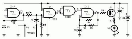
This plant watering monitor circuit is intended to signal when a plant needs water. A LED flashes at a low rate when the ground in the flower-pot is too dry, turning off when the moisture level is increasing. Adjusting R2 will allow the user to adapt the sensitivity of the circuit for different grounds, pots and probe types. IC1A and related components R1 and C1 form a 2KHz square wave oscillator feeding one gate input of IC1B through the voltage divider R2/R3 made variable by adjusting the Trimmer R2. If the resistance across the probes is low (as when there is a sufficient quantity of water into the pot) C2 diverts the square wave to ground, IC1B is blocked and its output will go steady hight. IC1C inverts the high status to low, thus keeping IC1D blocked: the LED is off.
When the ground in the flower-pot is becoming too dry the resistance across the probes will increase and C2 will be no longer able to divert the square wave to ground. Therefore, IC1B output begins to transfer the 2kHz signal to IC1C which, in turn, passes it to the oscillator built around IC1D.No longer disabled by a low level on its input, the IC1D oscillator slowly pulses Q1 base low causing the LED to flash, signalling the necessity to water the plant.
The short low pulse driving the base of Q1 is actually a burst of 2kHz pulses and therefore the LED flickers about 2,000 times per second – appearing to the human eye as if the LED was steadily on for the entire duration of the pulse.Some notes on this plant watering monitoring system
A square wave is used to avoid problems of probes oxidization.
Probes are made with two pieces of bare, stiff lighting cable of 1mm diameter and should be about 60mm long.
The probes should be driven fully in the pot’s ground about 30 – 50mm apart. Please note that all parameters regarding probes material, dimensions and spacing are not critical.
Current consumption: LED off = 150μA; LED on = 3mA for 0.1 sec. every about 2 sec. allowing the battery to last for years.
The quiescent current consumption is so low that the use of a power on/off switch was considered unnecessary. In any case, to switch the circuit completely off, you can short the probes.
Plant Watering Monitor circuit diagram
Components ValuesR1,R4 – 470K 1/4W ResistorsR2 – 47K 1/2W Trimmer Cermet or CarbonR3 – 100K 1/4W ResistorR5 – 3K3 1/4W ResistorR6 – 15K 1/4W ResistorR7 – 100R 1/4W Resistor
C1 – 1nF 63V Polyester CapacitorC2 – 330nF 63V Polyester CapacitorC3,C4 – 10μF 25V Electrolytic Capacitors
D1 – 1N4148 75V 150mA DiodeD2 – 5mm. Red LED
IC1 – 4093 Quad 2 input Schmitt NAND Gate IC
Q1 – BC557 45V 100mA PNP Transistor
P1,P2 – Probes (See Notes)
B1 – 3V Battery (2xAA, N or AAA 1.5V Cells in series) (View)
View full Circuit Diagram | Comments | Reading(907)
| Pages:56/312 At 204142434445464748495051525354555657585960Under 20 |
Circuit Categories
power supply circuit
Amplifier Circuit
Basic Circuit
LED and Light Circuit
Sensor Circuit
Signal Processing
Electrical Equipment Circuit
Control Circuit
Remote Control Circuit
A/D-D/A Converter Circuit
Audio Circuit
Measuring and Test Circuit
Communication Circuit
Computer-Related Circuit
555 Circuit
Automotive Circuit
Repairing Circuit