
Control Circuit
Index 51
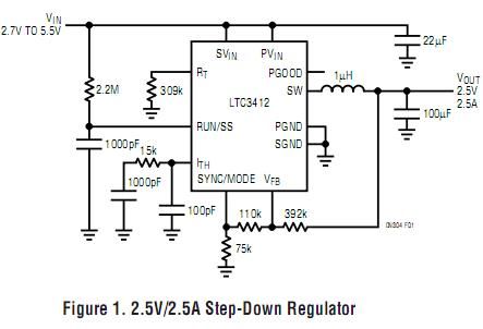
4MHz Monolithic Synchronous Step-Down Regulators
Published:2012/10/29 22:06:00 Author:muriel | Keyword: 4MHz, Monolithic Synchronous , Step-Down Regulators
View full Circuit Diagram | Comments | Reading(690)
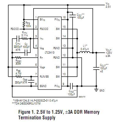
3A, 2MHz Monolithic Synchronous Step-Down Regulator
Published:2012/10/29 22:05:00 Author:muriel | Keyword: 3A, 2MHz, Monolithic Synchronous, Step-Down Regulator
View full Circuit Diagram | Comments | Reading(676)
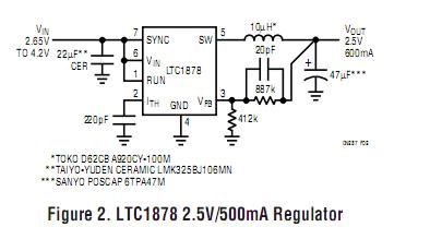
10µA Quiescent Current Step-Down Regulators
Published:2012/10/29 22:04:00 Author:muriel | Keyword: 10µA , Quiescent Current , Step-Down Regulators
View full Circuit Diagram | Comments | Reading(625)
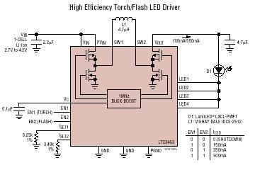
LTC3453 - Synchronous Buck-Boost High Power White LED Driver
Published:2012/10/29 22:03:00 Author:muriel | Keyword: LTC3453 , Synchronous Buck-Boost, High Power, White LED Driver
View full Circuit Diagram | Comments | Reading(1892)
No Design Switiching Regulator
Published:2012/10/29 22:01:00 Author:muriel | Keyword: No Design Switiching Regulator
View full Circuit Diagram | Comments | Reading(712)
Buck/Boost Charge-Pump Regulator Powers White LEDs from a Wide 1.6V to 5.5V Input
Published:2012/10/29 21:57:00 Author:muriel | Keyword: Buck/Boost, Charge-Pump Regulator, Powers White LEDs, Wide 1.6V to 5.5V Input
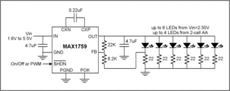
Since their invention a few years ago, white light-emitting-diodes (LEDs) have been steadily gaining in popularity. Because they offer whiter light and longer life than incandescent bulbs and are easier to use than fluorescent tubes, they have been steadily gaining market share in a variety of lighting applications, such as flashlights and display backlighting in handheld electronics. However, white LEDs present their own set of technical issues.An obvious issue for battery-powered equipment is the high forward voltage of white LEDs, which is typically 3.6V at 20mA and is usually specified as 3.0V minimum to 4.0V maximum. Once the voltage-drop of ballast resistors is added, the required bias voltage is even higher; therefore, typical battery systems require a voltage boosting DC-to-DC converter. Recently, several IC manufacturers have introduced various charge-pump and inductor-based boost converter ICs dedicated to driving white LEDs; however, at the time of this writing, none of these ICs support low-voltage operation from a two-cell stack of NiMH or alkaline batteries. Also, some of these dedicated ICs fail to regulate properly or even shutdown properly when presented with a 5V input, such as from a wall adapter. Although never intended for white LED bias applications, the MAX1759 buck/boost charge-pump is the first charge-pump to regulate white LEDs from a wide 1.6V to 5.5V input range. As implemented in the circuit of Figure 1, the MAX1759 will bias the LEDs with 15mA from inputs including two NiMH cells, two alkaline cells, three NiMH cells, three alkaline cells, a single Li+ cell, a regulated I/O voltage of 2.5V or 3.3V, a 5V wall adapter, or any combination of these for flexible systems. Unlike most charge-pumps, the IC incorporates a buck mode for proper regulation with 5V inputs, and internal circuitry fully disconnects the output in shutdown, eliminating LED leakage current and associated battery drain when off. Other features include PWM dimming via the active-low SHDN pin and fold-back current limiting for short-circuit protection. (View)
View full Circuit Diagram | Comments | Reading(835)
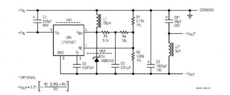
Buck Mode Switching Regulator for Solar Applications
Published:2012/10/29 21:56:00 Author:muriel | Keyword: Buck Mode, Switching Regulator , Solar Applications
View full Circuit Diagram | Comments | Reading(1335)
Voltage follower with 1G ohm input resistance
Published:2012/10/29 21:54:00 Author:muriel | Keyword: Voltage follower, 1G ohm input resistance
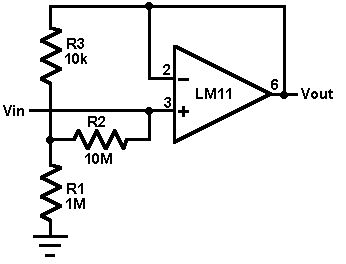
This circuit uses an LM11 to form a voltage follower with 1G ohm input resistance built using standard resistor values. With the input disconnected, the input offset voltage is multiplied by the same factor as R2; but the added error is small because the offset voltage of the LM11 is so low. When the input is connected to a source less than 1G ohm, this error is reduced. For an ac-coupled input a second 10M resistor could be connected in series with the inverting input to virtually eliminate bias current error; bypassing it would give minimal noise.
(View)
View full Circuit Diagram | Comments | Reading(943)
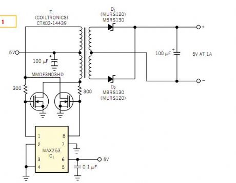
Push-pull driver provides isolated 5V at 1A
Published:2012/10/29 21:53:00 Author:muriel | Keyword: Push-pull driver , 5V , 1A
View full Circuit Diagram | Comments | Reading(2249)
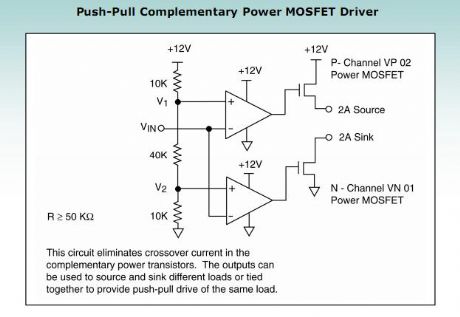
push-pull complementary power MOSFET driver
Published:2012/10/29 21:52:00 Author:muriel | Keyword: push-pull , complementary power , MOSFET driver
View full Circuit Diagram | Comments | Reading(2349)
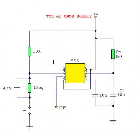
Switch De-Bouncer
Published:2012/10/29 21:49:00 Author:muriel | Keyword: Switch De-Bouncer
View full Circuit Diagram | Comments | Reading(923)
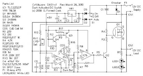
DAS1 - 12 Volt 10 Amp Dark Activated Switch
Published:2012/10/29 21:36:00 Author:muriel | Keyword: DAS1 - 12 Volt, 10 Amp, Dark Activated Switch
View full Circuit Diagram | Comments | Reading(1149)
LOW acoustic-optical siren circuit
Published:2012/10/28 21:02:00 Author:Ecco | Keyword: LOW , acoustic-optical siren
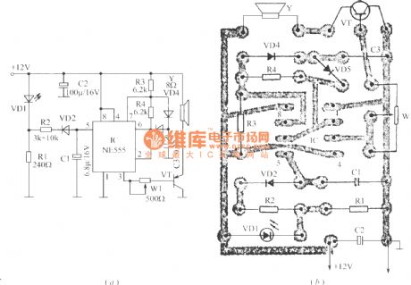
The circuit can generate high intensity warning sound, and it can be used as anti - theft siren. When power alarm system is connected, VD1 flashes and eimts light, R1 resistor outputs pulse square wave which is converted into triangle wave after passing R2, VD2 and C1 network, IC is a 555 time-base circuit to form a voltage-controlled oscillator. R3, R4 and C3 are timing elements. Under the control of the triangular wave, the output variable tone signals is amplified by VT to promote speakers, and its output power closes to l0W. Adjusting R1 can change the amplitude of the triangle wave on C1, and adjusting W1 can change the volume. Figure (b) is a printed circuit board installation diagram.
(View)
View full Circuit Diagram | Comments | Reading(1267)
PC control three-phase motor circuit for buck and starting
Published:2012/10/26 22:02:00 Author:Ecco | Keyword: PC control, three-phase motor, buck and starting
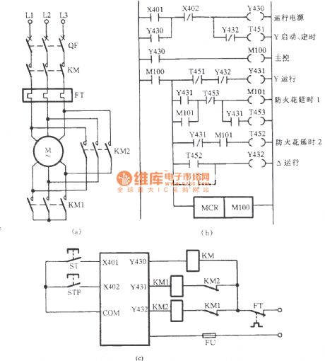
Figure (a) is the primary circuit which is a common Y-△ buck start circuit; Figure (b) is the Y-△ buck starting automatic control system circuit with FX2-40MR-Y PC design; Figure (c) shows the external wiring diagram of system.
(View)
View full Circuit Diagram | Comments | Reading(1295)
Preamp and 330 + MHz Prescaler
Published:2012/10/25 21:40:00 Author:muriel | Keyword: Prescaler, 330 + MHz
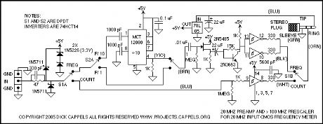
Signals applied to the input connector can be switched either through the AC path which includes the preamp and the prescaler, if switched into the circuit, or the DC path, which routes the signal to a Schmitt trigger buffer that then sends the signal on to the counter.Regardless of how the signal is routed, it must first pass through an input protection network, which includes two schottky diodes and a zener clamp. The 1N5711 schottky diodes prevent the input signal from going more than a schottky diode drop below ground or above the power supply. I used Schottky diodes because they have a lower voltage drop than the PN protection diodes on the CMOS integrated circuit they are intended to protect, and as such, they will draw much more of the current from excessive input voltages than the input protection diodes in the integrated circuits.The two 1N5226 zener diodes in series prevents the power supply from rising above 6.6 volts in case the input is accidentally connected to a low impedance source that is higher than 5 volts. The 47 Ohm resistor limits the input current in case of excessive voltage being applied to the inputs.The input of the frequency meter requires a full 5 volt CMOS logic swing, and the prescaler's output is less than 1 volt peak-to-peak, so the prescaler, when switched into the circuit, the signal goes through the prescaler, then the preamp, and the preamp drives the frequency meter through the Schmidt trigger buffers.The MCT10280 prescaler can be set to divide by 80, 40, 20, or 10, as a function of which pins are tied to the power supply. I set this one to divide by 10 since it is adequate for my needs, and the mental calculation of multiplying the meter reading by 10 is not taxing. One problem with the MCT10280 is that if it doesn't have an adequate input, the output is very noisy, which shows up as counts in the couple MHz range on the frequency meter. This noise shows up if the signal amplitude the signal frequency is too low. For this reason, I only intend to use the prescaler with inputs between 10 MHz and 300 MHz.
(View)
View full Circuit Diagram | Comments | Reading(1266)
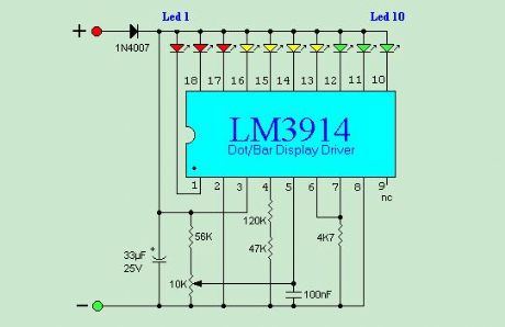
12 V LEAD-acid monitor
Published:2012/10/25 21:39:00 Author:muriel | Keyword: 12 V, LEAD-acid monitor
View full Circuit Diagram | Comments | Reading(968)
Alarm circuit diagram using op amp
Published:2012/10/25 21:29:00 Author:Ecco | Keyword: Alarm , op amp
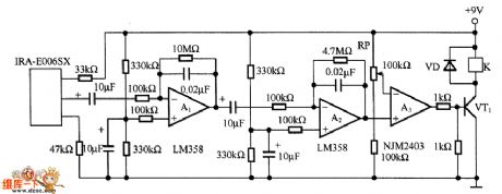
A1 and A2 form the two-stage amplifier which can amplifer output signal of pyroelectric sensor IRA-E006SX to a desired level. A3 is a comparator, and RP adds reference voltage to the inverting input terminal of A3, whe A2 output level is higher than the reference voltage, A3 outputs a high level to make VT1 conduction, relay κ action to drive the alarm.
(View)
View full Circuit Diagram | Comments | Reading(1341)
The alarm circuit diagram using DS-505 pyroelectric sensor
Published:2012/10/25 21:26:00 Author:Ecco | Keyword: alarm , pyroelectric sensor
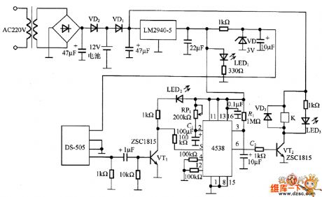
In the circuit, DS-505 receives the infrared radiation from human body and turned it into a voltage signal, then it is amplified by VT1 and added pin 5 of 4538 ( B - side) to start timer, then the pin 6 ( Q side) outputs high level, and VT2 gets conduction to drive relay K action its contacts are connected to the alarm device alarm. In the circuit, the timing time is determined by the time constant of RP1 and C1, R1 and C2 are used to prevent the erroneous operation of the timer when the power is turned on , LED1, LED2 and LED3 respectively show the power supply, sensor output and the operation of the relay.
(View)
View full Circuit Diagram | Comments | Reading(1982)
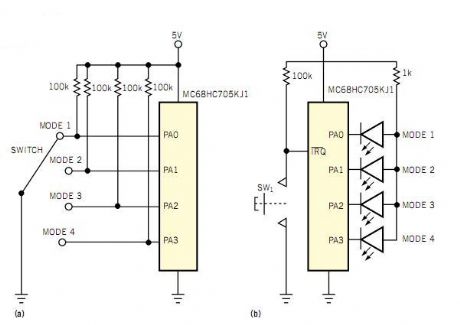
Cheap pushbutton replaces rotary switch
Published:2012/10/25 20:50:00 Author:muriel | Keyword: Cheap pushbutton, replaces , rotary switch
View full Circuit Diagram | Comments | Reading(976)
Guitar Control
Published:2012/10/25 3:08:00 Author:muriel | Keyword: Guitar Control
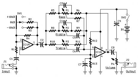
Stand-alone, 9V battery powered unit
Three-level input selector, three-band tone control (View)
View full Circuit Diagram | Comments | Reading(1488)
| Pages:51/312 At 204142434445464748495051525354555657585960Under 20 |
Circuit Categories
power supply circuit
Amplifier Circuit
Basic Circuit
LED and Light Circuit
Sensor Circuit
Signal Processing
Electrical Equipment Circuit
Control Circuit
Remote Control Circuit
A/D-D/A Converter Circuit
Audio Circuit
Measuring and Test Circuit
Communication Circuit
Computer-Related Circuit
555 Circuit
Automotive Circuit
Repairing Circuit