
Control Circuit
Index 59
Light Operated Relay circuit
Published:2012/9/19 21:26:00 Author:Ecco | Keyword: Light Operated, Relay
This Light Sensitive Circuit can operate a Relay to switch on Lamps or any AC loads when it senses darkness. It is ideal to use as switch less Night lamps driver.
LDR is used as the light sensor. Its resistance is low about 100 ohms in bright light but increases to 10 meg or more in dark. Preset VR1 set the sensitivity of the LDR. During day time LDR conducts so that the gate of T1 will not get base bias. So that relay remains de energized. When the intensity of light reduces, LDR offers more resistance and more current passes to the base of T1 and it conducts. Relay then switch on the load. Adjust VR1 to trigger relay at the particular light level. LED indicates the activation of relay.
Light Operated Relay Circuit
?
8 Responses to “Light Operated Relay circuit”
Source: electroschematic.com
(View)
View full Circuit Diagram | Comments | Reading(1248)
Tiny Door Guard with Alarm
Published:2012/9/19 21:23:00 Author:Ecco | Keyword: Tiny Door Guard , Alarm
This simple Door Chime protects the door and gives a loud Alarm tone when there is an attempt of theft. The circuit is too simple and battery operated.
A Normally Closed (NC) reed switch and magnet is used to trigger the circuit. Alarm generator is the popular ROM IC UM 3561. This 8 pin IC has an inbuilt oscillator to generate 4 siren tones like, Ambulance siren, Police siren, Fire brigade siren and Gun sound. The different tones can be selected using its pin 6 connected to VCC, Ground or not connected. Frequency of oscillation is determined by the 220K resistor connected to the pins 7 and 8 of the IC.UM 3561 is the low power IC and its maximum voltage rating is 3 volts. So Zener diode ZD is used to give 3 volts supply to IC. Medium power NPN transistor T1 amplifies the output pulses from IC1 to a loud siren.
Tiny Door Guard Circuit
Magnet can be a small sized one that is to be fixed in the door using double sided adhesive tape. Fix the circuit board in the door frame. Fix Reed switch in the door frame, very close to the door. So that, when the door is closed, the magnet will pull the contacts of the reed switch to break supply to the IC. When the door opens, contacts of the reed switch make contact and IC gets power to give alarm.?
15 Responses to “Tiny Door Guard with Alarm”
Source: electroschematic.com
(View)
View full Circuit Diagram | Comments | Reading(884)
DC Fan Controller circuit
Published:2012/9/19 21:23:00 Author:Ecco | Keyword: DC, Fan Controller
This circuit is ideal to control the cooling fan of heat generated electronic gadgets like power amplifiers. The circuit switches on a fan if it senses a temperature above the set level. The fan automatically turns off when the temperature returns to normal.The circuit uses an NTC (Negative Temperature Coefficient) Thermister to sense heat. NTC Thermister reduces its resistance when the temperature in its vicinity increases.IC1 is used as a voltage comparator with two potential dividers in its inputs. Resistor R1 and VR1 forms one potential divider connected to the non inverting input of IC1 and another potential divider comprising R2 and the 4.7K Thermister supplying a variable voltage to the inverting input of IC1. VR1 is adjusted so as to give slightly lesser voltage at the non inverting input than the inverting input at room temperature. In this state, output of IC1 will be low and the Fan remains off. When the temperature near the Thermister increases, its resistance decreases and conducts. This drops the voltage at pin 2 of IC1 and its output becomes high. T1 then triggers and fan turn on. Red LED indicates that fan is running. Capacitor C1 gives a short lag before T1 turns on to avoid false triggering and to give proper bias to T1.DC fan can be the one used in Computer SMPS.
DC Fan Controller Circuit
Keep the Thermistor near the heat sink of the Amplifier PCB and switch on the amplifier for 10 minutes. Then adjust VR1 till the Fan stop running.When the temperature rises, Fan will automatically switch on.?
4 Responses to “DC Fan Controller circuit”
Source: electroschematic.com
(View)
View full Circuit Diagram | Comments | Reading(1273)
Temperature monitor circuit
Published:2012/9/19 21:21:00 Author:Ecco | Keyword: Temperature monitor
This temperature monitor circuit is used where a continous analog display of temperature value being monitored is not necessary. A simple indication whether the temperature value exceeded a maximum level or went below the minimum level is sometimes enough. The circuit here does just that, it indicated the temperature level about +25oC (77oF) or below +20oC (68oF) by lighting one of the two LEDs. The temperature sensor is an NTC resistor coupled to two comparators. When D1 lights, the temperature is above +25oC and when D2 lights, the temperature is below +20oC.Temperature monitor calibration
Place the NTC resistor in cold water. Slowly heat the water until the desired maximum temperature level is reached, then adjust P1 until D2 lights up.
To set the minimum level, stop heating the water then slowly add cold water to it until the desired lower temperature level is reached as indicated by the thermomter. This time adjust P2 until D1 lights up.
Temperature level monitor circuit schematic
?
2 Responses to “Temperature monitor circuit”
Source: electroschematic.com (View)
View full Circuit Diagram | Comments | Reading(1208)
Kitchen Exhaust Fan Controlled by Temperature
Published:2012/9/19 21:19:00 Author:Ecco | Keyword: Kitchen Exhaust Fan, Controlled by Temperature
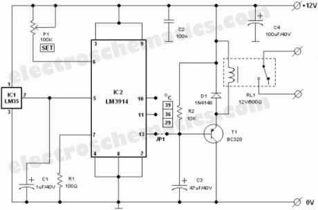
Exhaust fan is an important component in kitchens. Here is a simple circuit to control kitchen fans by monitoring the ambient temperature. It is built around the renowned precision integrated temperature sensor chip LM35 (IC1). Rest of the circuit is a non-traditional electromagnetic relay driver wired around the popular LED driver LM3914 (IC2). User can switch three presetted temperature levels using a jumper/slide switch (JP1), which determines the heat level to activate the relay and hence the electric exhaust fan wired through the relay contacts. It works off 12V DC power supply.
Kitchen Fan Controller Circuit Schematic
Only one adjustment is required in this kitchen exhaust fan controller circuit. After construction, set jumper point in its first position, ie base terminal of T1 is connected to pin 13 of IC2 and adjust the preset P1 carefully so that relay RL1 is energised when ambient temperature level reaches near 29oC. However this is not very critical as you can select any threshold level by connecting the jumper points to other unused output pins of IC2 (here only 3 outputs are used). More details about LM3914 and/or LM35 are available as pdf datasheet from NSC website.
Source: electroschematic.com (View)
View full Circuit Diagram | Comments | Reading(2175)
Polarity protection circuit
Published:2012/9/19 21:18:00 Author:Ecco | Keyword: Polarity protection
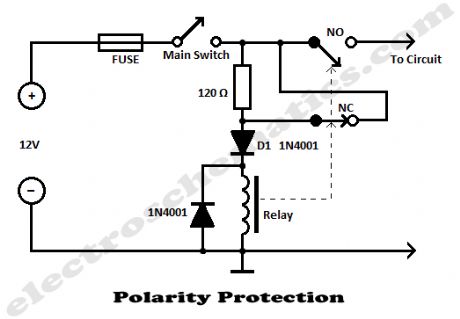
The most simple polarity protection tehnique is to connect a series diode to the power line input. The diode conducts only when the power supply protection is correct. But the incovenient is that at higher current levels, the voltage drops and power loss of the diode affects the power level adversely.This polarity protection circuit is dimensioned for 12 V power supplies and avoids the voltage and power loss problem. By correct polarity, the current flowing to the D1 and the relay coil causes the relay contacts to activate. The NO contact closes powering the electronic device. The NC contact opens and the current supplying the relay coil is reduced to a low level just enough to maintain relay activation.
Polarity protection circuit schematic
When reversed polarity occurs, the diode blocks the current and the relay cannot activate. The NO contact remains open and the electronic device is protected from the reversed polarity voltage.
3 Responses to “Polarity protection circuit”
Source: electroschematic.com (View)
View full Circuit Diagram | Comments | Reading(1383)
Temperature relay circuit
Published:2012/9/18 21:25:00 Author:Ecco | Keyword: Temperature relay
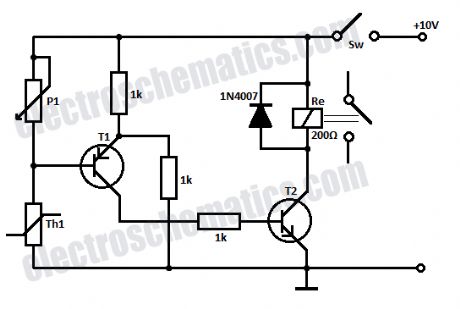
This simple temperature relay circuit can be used to signal a fire or setpoint for temperature monitoring function. You need to adjust P1 so that T1′s base voltage is 0.5V smaller than the emitter voltage at a temperature a little bit lower than the desired triggering (switching) temperature.If the temperature increases then T1 and T2 start conducting and the relay is closed (ON). If you want to use it as a cold relay or to signal an inferior temperature limit, then Th1 and P1 change places. After the relay is triggering you need to open switch S1 in order to stop the circuit. The nominal value of P1 must be choosed according to the used NTC thermistor and the switching temperature to be adjusted.
Temperature relay schematic
T1 can be BC557 and T2 BC547.
One Response to “Temperature relay circuit”
Source: electroschematics.com
(View)
View full Circuit Diagram | Comments | Reading(1764)
12V LDO Solar Charge Control
Published:2012/9/18 21:16:00 Author:Ecco | Keyword: 12V , LDO , Solar Charge Control
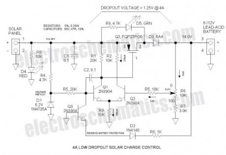
This Low Dropout Voltage (LDO) solar charge control uses a simple differential amplifier and series P channel MOSFET linear regulator—their compatibility seems like a marriage made in heaven. Voltage output is adjustable. It is mainly intended for charging 12V lead-acid batteries.Solar Charge Control Specifications
Solar panel rating: 50W (4A, 12V nominal) (open circuit voltage: 18 to 20V)
Output voltage range: 7 to 14V (adjustable) (not recommended for 6V applications)
Max power dissipation: 16W (includes power dissipation of D3)
Typical dropout voltage: 1.25V @ 4A
Maximum current: 4A (current limiting provided by solar panel characteristics)
Voltage regulation: 10mV (no load to full load)
Battery discharge: 1mA (Chinese controls discharge at typically 5mA)
LED indicators:
RED: Solar panel active
GREEN: Series regulator limiting current (fully charged or topping off)
Reverse battery protection: Control shuts down if battery is inadvertently connected reverse
12V Solar Charge Control Schematic
Bill of Materials
In Excel format (download link at the bottom)
Dropout Voltage
The input voltage exceeds the input voltage by 1.25V when charging at the maximum rate—the lower, the better. Low Dropout Voltage (LDO) is the catch phrase for anything under approximately 2V. This could potentially be reduced to below 1V by making D3 a schottky rectifier.
Current Limiting
Current limiting is provided by the solar panel—it is not a commonly understood fact that the solar panel tends to be a constant current device. For this reason, a solar panel can withstand a short circuit. Therefore, the control does not need current limiting.
Float Charge of Lead-Acid Batteries
This control charges the battery at a constant voltage and also maintains a charged battery (float charge). The float charge voltage specification is a little lower than the charge voltage, so to accommodate both voltages, a compromise is reached by simply reducing the voltage slightly—that is how ALL automotive systems operate. To obtain maximum charge in a 12V battery, set the control to 14 to 14.6V. Automotive systems further reduce voltage to 13 to 13.5V in order to accommodate high temperature operation as the battery is usually located in the hot engine compartment—battery has a negative thermal coefficient of voltage.
Voltage Adjustment
To set the voltage, disconnect the battery and connect a 1K dummy load resistor to the output. The resistor is necessary to shunt potential MOSFET leakage current as well as the green LED current.
LDO Solar Charge Control Circuit Operation
R4 and D1 form a 6V shunt zener voltage reference. Q1 & Q2 make up the classic differential amplifier that amplifies the difference between the reference voltage and the feedback voltage from the arm of potentiometer R6. The output is taken from the collector of Q2 and drives the gate of P Channel MOSFET Q3. Differential voltage gain is probably in the order of 100 to 200. For best performance, I selected Q1 & Q2 for matched hFE. As the feedback voltage increases at the arm of R6, Q2 turns on harder and steals some of the emitter current away from Q1. The collector current of Q1 follows the emitter current and drops less voltage across R1 thus reducing Vgs of Q3 and turning it off. C2 provides frequency compensation to pr
Source: electroschematics.com (View)
View full Circuit Diagram | Comments | Reading(2984)
The voice control flowing Lantern associated with many famous songs circuit ( 5G167 )
Published:2012/9/18 1:42:00 Author:Ecco | Keyword: voice control , flowing Lantern , many famous songs
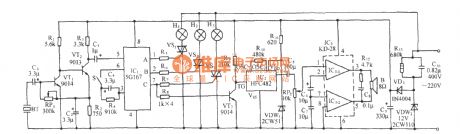
As shown in the figure, the circuit consists of acoustic / electric sensor, audio amplifier, ring count pulse distribution / driver circuit, SCR control circuit, songs sound circuit, audio amplifier circuit and AC buck rectifier circuit. IC1 uses 5G167, it is designed for ring count pulse distribution / driver ICs used in tape recorders rotary flash box, it contains the signal rectifier amplifier, voltage controlled oscillator and 3-bit ring timing counter and 3 drain output circuits and so on.
(View)
View full Circuit Diagram | Comments | Reading(833)
Triac governor circuit
Published:2012/9/18 1:48:00 Author:Ecco | Keyword: Triac governor
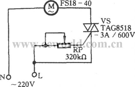
The motor M and TRIAC VS are connected in series, if changing the conduction angle of the VS, the AC voltage applied to both ends of the motor M can be changed to realize stepless speed adjust in the range of 0 ~ 220V. General Triac trigger circuit is more complex with a lot of components. The circuit shown in figure only uses a potentiometer RP to achieve speed control purposes. It uses equipotential trigger circuit , i.e. whether it is a positive trigger or a negative trigger, the control electrode G and the potential of the cathode of T2 are the same. This circuit can be used the governor in fan, incandescent dimmer or other household appliances.
(View)
View full Circuit Diagram | Comments | Reading(2879)
Bathroom door control switch circuit ( 2 )
Published:2012/9/18 2:04:00 Author:Ecco | Keyword: Bathroom , door control switch
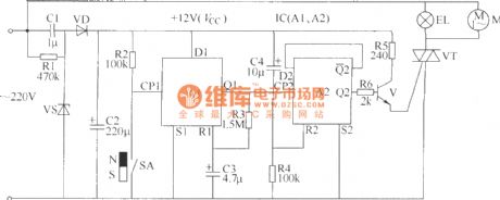
The circuit is used to control the bathroom lights and exhaust fan. When someone opens the door and comes to the bathroom, the door control switch is turned on, the bathroom light will be lit and exhaust fan is also energized; When users open the door and come out of the bathroom, the door control switch is turned off, lights will be turned off, the exhaust fan is also interrupted.The bathroom door control switch circuit inlcudes the power circuit, monostable flip-flop, flip-flop circuit and control execution, and it is shown in the figure.
(View)
View full Circuit Diagram | Comments | Reading(1393)
Speaker protection circuit
Published:2012/9/17 1:19:00 Author:Ecco | Keyword: Speaker, protection circuit
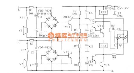
The speaker protection circuit is shown in the figure. It has the left and right channels to work independently. In the Figure ( left channel ), R2 , C4, VT2 and VT3 form a starting up delay circuit to prevent the starting up high-current impact on speaker.
Components Selection: LED can choose Φ3mm high-brightness color LED. Since LED current may be high or low, the parameters of R5, R9 can be slightly adjusted. At the same time, the LED and the current limit resistors R5, R9 are connected to two ends of relays RE1 and RE2 in parallel to inhibit the anti-peak voltage and prevent the breakdown from VT2, VT3, VT5 and VT6. C4, C9 should use low-leakage tantalum capacitors. Other components parameters are shown in the figure.
(View)
View full Circuit Diagram | Comments | Reading(4495)
Frequency shift keying modulation and demodulation circuit with XR-2207
Published:2012/9/17 1:28:00 Author:Ecco | Keyword: Frequency shift, keying modulation , demodulation
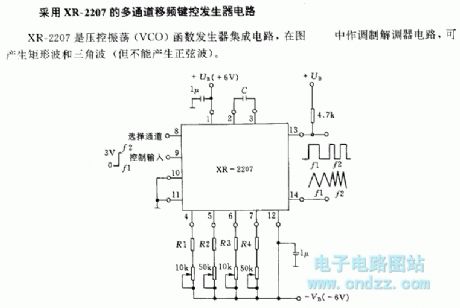
XR-2207 is a a voltage - controlled oscillation (VCO) function generator integrated circuit, and it is used as modulation and demodulation circuit to generate rectangular wave and triangular wave (but it can not generate sine wave ).
(View)
View full Circuit Diagram | Comments | Reading(2377)
DC motor start circuit controlled by counter electromotive force
Published:2012/9/17 1:39:00 Author:Ecco | Keyword: DC motor start , counter electromotive force
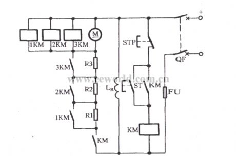
When breaker QF is closed, pressing the start button ST will make DC contactor KM pull in, the motor M connected to R1 , R2, R3 in series is started. With the speed increaseing, the counter electromotive force increases, the voltage at both ends of the motor M is increased gradually, so that 1KM, 2KM, 3KM operate in an order, the main contacts will sequentially shorting connect R1, R2, R3, and finally the motor M is put into full pressure operation. 1KM, 2KM, 3KM are DC contactors, the pull-in coil's rated voltage must meet U1KM < U2KM < U3KM.
(View)
View full Circuit Diagram | Comments | Reading(1513)
The overtemperature sprinkler cooling device circuit for menagerie building
Published:2012/9/17 1:44:00 Author:Ecco | Keyword: overtemperature sprinkler , cooling , menagerie building

The circuit is shown as the figure. It consists of temperature detecting circuit, voltage comparator circuit, power switch circuit, croak sound circuit, AC buck rectifier circuit and other components. When indoor temperature is more than 32℃ in summer, it can automatically start the sprinkler to cool temperature. When the room temperature falls below a predetermined temperature, it stops the sprinkler. The circuit is suitable for the breeding of rare birds and animals, the circuit is simple with reliable performance. When the sprinkler works, it also issued the acoustic sound of frogs calling to attract to the attention of the personnel on duty.
(View)
View full Circuit Diagram | Comments | Reading(996)
Automatic thermostat with birds sound circuit
Published:2012/9/14 2:04:00 Author:Ecco | Keyword: Automatic thermostat , birds sound
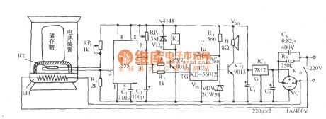
The circuit is shown in Figure, and it consists of thermal sensor head, monostable trigger circuit, birdsong sounding circuit and AC buck rectifier circuit. It enables the electric apparatus and the storage to keep in a set temperature range, when the temperature is lower than the minimum temperature because of the heat leaving from apparatus, the heater is automatically turned on for heating with several birdsong.
(View)
View full Circuit Diagram | Comments | Reading(1286)
Ed Gray Motor Generator
Published:2012/9/16 21:56:00 Author:Ecco | Keyword: Ed Gray, Motor Generator
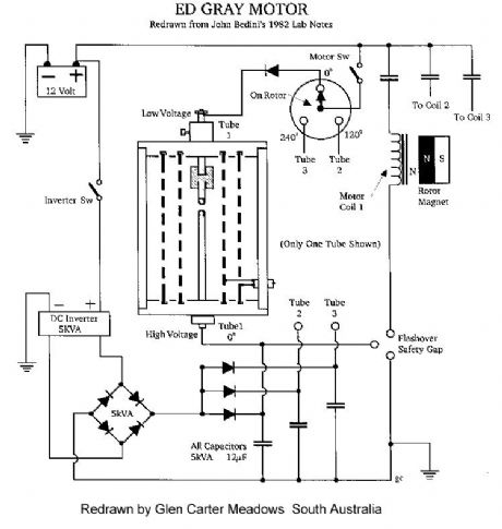
This type of design can produce a very high amperage current for a faction a second that can used to do some useful work if properly harnessed. The switching device could be a rotating spark gap as used by Nikola Tesla or some high speed electronic device, it is my belief that only glass tubes such as diodes or triode valves are really good at this and not transistors as they cannot handle the high voltage and high current produced in these devices without burning themselves out. (View)
View full Circuit Diagram | Comments | Reading(3539)
Free energy magnet motor
Published:2012/9/16 21:44:00 Author:Ecco | Keyword: Free energy , magnet motor
This invention relates to a method of producing useful energy with magnets as the driving force and represents an important improvement over known constructions and it is one which is simpler to construct, can be made to be self starting, is easier to adjust, and is less likely to get out of adjustment. The present construction is also relatively easy to control, is relatively stable and produces an amazing amount of output energy considering the source of driving energy that is used. (View)
View full Circuit Diagram | Comments | Reading(6849)
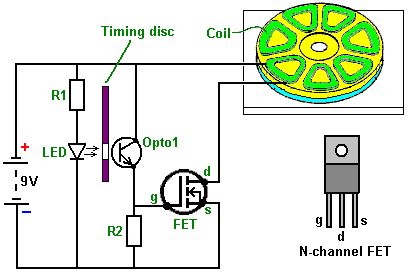
Delay circuit with NE555 timer
Published:2012/9/16 20:48:00 Author:Ecco | Keyword: Delay , timer
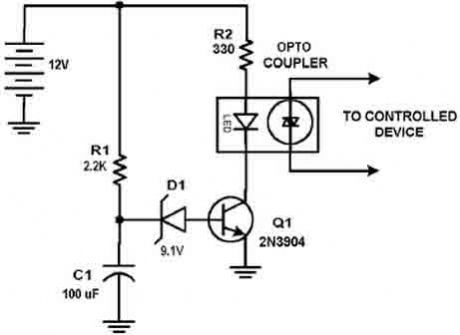
This circuit design was used to switch on device via a LED photocell arrangement (optocoupler) using components R1, C1, D1 and Q1. It produces a delay on powering up to ensure correct sequencing of certain equipment. A very simple delay timer using a single transistor and an R-C timing circuit.
(View)
View full Circuit Diagram | Comments | Reading(0)
Anti-bag-snatching alarm circuit
Published:2012/9/16 20:34:00 Author:Ecco | Keyword: Anti-bag-snatching, alarm
This circuit, enclosed in a small plastic box, can be placed into a bag or handbag. A small magnet is placed close to the reed switch and connected to the hand or the clothes of the person carrying the bag by means of a tiny cord. If the bag is snatched abruptly, the magnet looses its contact with the reed switch, SW1 opens, the circuit starts oscillating and the loudspeaker emits a loud alarm sound. (View)
View full Circuit Diagram | Comments | Reading(1183)
| Pages:59/312 At 204142434445464748495051525354555657585960Under 20 |
Circuit Categories
power supply circuit
Amplifier Circuit
Basic Circuit
LED and Light Circuit
Sensor Circuit
Signal Processing
Electrical Equipment Circuit
Control Circuit
Remote Control Circuit
A/D-D/A Converter Circuit
Audio Circuit
Measuring and Test Circuit
Communication Circuit
Computer-Related Circuit
555 Circuit
Automotive Circuit
Repairing Circuit