
Control Circuit
Index 49
Cheap 40KHz clock
Published:2012/11/9 0:30:00 Author:muriel | Keyword: Cheap , 40KHz , clock
Use a 40KHz Xtal and a 74C14 schmitt trigger:
________ <---------------- 2.2 M resistor
___| 2M2 |___
| |________| |
| |
| |
| |\ |
| | \ |
+-----| O------+--------> Output 40KHz
| | /
| |/ gate 1 of 74C14
|
|
--+--
XXX 40KHz Xtal
--+--
|
|
-----
---
-
This circuit has worked for me in many applications. (it might be an idea to buffer the signal befor using it. (There are still 5 unused gates in the 'C14.. :-) (View)
View full Circuit Diagram | Comments | Reading(755)
Building an Intel 8008 Computer "Clock"
Published:2012/11/9 0:29:00 Author:muriel | Keyword: Intel 8008 Computer, "Clock"

Be aware that I cheated this time around, at least I feel that way. In this design I use many modernly available shortcuts such as programmable logic devices and a high density ram. These devices were not available back in the 70’s. In doing so I do not believe I compromised my goal. My goal was to build a clock, not become crippled and blind, wire-wrapping two hundred IC’s. Unlike my teenage years, I don’t have unlimited time, and I now have a mortgage… I no longer mow lawns for a living, as I did at fourteen.
Please understand this is a fully operational 8008 computer. Its 16k of memory space can be configured to use several combinations or RAM and EPROM. I designed in four input and four output ports. It also has a fully functional front panel that can be used to examine or modify memory, or jam in an interrupt instruction. If you are a purest, feel free to convert the PLD algorithms to random logic to build a more authentic computer, though doing so may require modifications to compensate for timing delays. Also remember you cannot load the 8008 down with more than one TTL load. You must buffer all signal lines coming from the CPU. You should also keep in mind that adding more logic chips will increase the power requirements.
(View)
View full Circuit Diagram | Comments | Reading(1220)
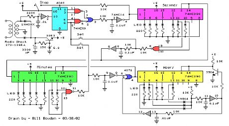
Binary Coded Decimal (BCD) Clocks
Published:2012/11/9 0:26:00 Author:muriel | Keyword: Binary Coded Decimal (BCD) , Clocks
View full Circuit Diagram | Comments | Reading(1189)
7-Segment LED Counter
Published:2012/11/9 0:22:00 Author:muriel | Keyword: 7-Segment, LED Counter
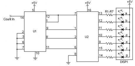
This simple counter can be used to count pulses, as the basis for a customer counter (like you see at the doors of some stores), or for anything else that may be counted. The circuit accepts any TTL compatible logic signal, and can be expanded easily (see Notes). (View)
View full Circuit Diagram | Comments | Reading(122)
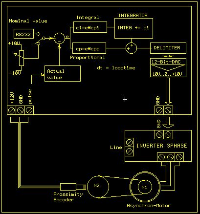
PID Motor control
Published:2012/11/9 0:21:00 Author:muriel | Keyword: PID Motor control
View full Circuit Diagram | Comments | Reading(1072)
24 Second Shot Clock
Published:2012/11/9 0:19:00 Author:muriel | Keyword: 24 Second , Shot Clock
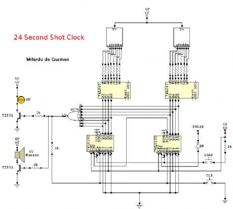
This is a circuit intended to be used in basketball shot clock.Notes:To start in 24 seconds; 24s LOAD SW and Reset SW should be push simultaneously. If not, the count will start in 99. Pulse input can be connected to 555 astable multivibrator but must be calibrated for real time clock. The PAUSE SW must have a Switch Debouncer so that the counter will count normal when counting is paused and then turn-on.When the count reach 00, the NOR gate will have an output of logic1 that will turn on the two transistor. The buzzer will rung and light will turn on. The two transistors are continuously turn-on not until LOAD SW and Reset SW is push. All have a +5v power supply. (View)
View full Circuit Diagram | Comments | Reading(1868)
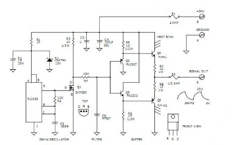
SQUARE WAVE DRIVER HAS FLEXIBLE OUTPUTS
Published:2012/11/8 23:59:00 Author:muriel | Keyword: SQUARE WAVE DRIVER, FLEXIBLE OUTPUTS
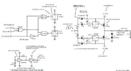
This circuit can produce an output signal ranging from DC to 100KHz. It can source a voltage ranging from 1v to 30v. It can sink a voltage ranging from zero volts to �30v. It can drive up to 200ma of current and can even be switched to a floating tristate output.
(View)
View full Circuit Diagram | Comments | Reading(1025)
Simple Methods Reduce Input Ripple for All Charge Pumps
Published:2012/11/8 23:57:00 Author:muriel | Keyword: Reduce Input Ripple, All Charge Pumps
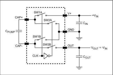
Charge pumps are a form of DC-DC converter that rely on capacitors instead of inductors for energy storage and transfer. The absence of inductors makes them attractive in situations requiring a low-power auxiliary supply (output currents up to about 150mA). They use less circuit-board area, offer minimal component height, and are easy to use.Charge pumps can have regulated or unregulated outputs. An unregulated charge pump either doubles or inverts the voltage that powers it and the output voltage is a function of the supply voltage. A regulated charge pump either boosts or inverts the supply voltage. Its output voltage is independent of the supply.Techniques that reduce capacitor size and optimize output current—fast switching speed and low-on-resistance switches—also produce noise and transient ripple at the input supply pin. Noise can propagate back along the input supply pins, creating problems for crystal-controlled oscillators, VCOs, and other sensitive circuits with poor power-supply rejection. This article focuses on methods for reducing the noise. (View)
View full Circuit Diagram | Comments | Reading(797)
Miniature, Precision Negative Reference Requires No Precision Resistors
Published:2012/11/8 23:55:00 Author:muriel | Keyword: Miniature, Precision , Negative, Reference, No Precision Resistors
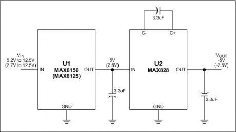
Switched-capacitor charge-pumps, which occupy less space than do their inductor-based counterparts, are popular for providing inverted voltages in small hand-held equipment. Combining a switched-capacitor charge-pump with a precision reference, for example, yields an inverted reference from a positive power supply (Figure 1). Unlike the more typical combination of a positive 3-terminal reference and an op-amp inverter, this one delivers accurate inversions without the need for precision resistors and a negative supply. The charge-pump inverter (U2) delivers -5V by inverting the output of a 5V precision reference (U1). U1 accepts inputs between 5.2V and 12.5V. Replacing it with a 2.5V reference that accepts 2.7V to 12.5V, as in the MAX6125, produces a -2.5V output. This circuit is very compact. It needs only three surface-mount capacitors, and the ICs occupy tiny SOT23 packages. (View)
View full Circuit Diagram | Comments | Reading(750)
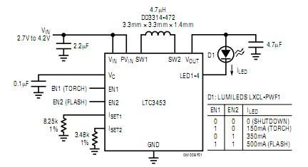
Low Noise White LED Driver with LED Current Control
Published:2012/11/8 23:53:00 Author:muriel | Keyword: Low Noise, White LED Driver , LED Current Control
View full Circuit Diagram | Comments | Reading(838)
HIGH POWER TOUCH SWITCH EXCITER CIRCUITS
Published:2012/11/8 1:34:00 Author:muriel | Keyword: HIGH POWER, TOUCH SWITCH , EXCITER CIRCUITS
View full Circuit Diagram | Comments | Reading(1160)
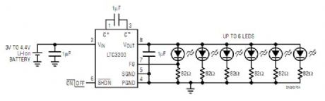
Compact, Inductor less Boost Circuit Regulates White-LED Bias Current
Published:2012/11/8 1:31:00 Author:muriel | Keyword: Compact, Inductor , less Boost Circuit, White-LED Bias Current
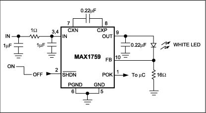
The increasing use of color LCDs in hand-held equipment is creating a need for smaller and cheaper sources of white backlight. Cold-cathode fluorescent lamps (CCFLs) and electro-luminescent (EL) panels have been used in the past, but those circuits are excessively large, expensive, and complex for today's hand-held, consumer-electronics devices. Fortunately, recent advances in LED technology have produced an LED that emits white light. White LEDs have several advantages over conventional types, including small size, low cost, low complexity, and high reliability.The typical forward-bias voltage for white LEDs is about 3.5V ±10%. To obtain white light you simply forward-bias the device, but a boost circuit is required because the white LED's forward voltage can be greater than the battery voltage. The conventional approach to this problem—a boost regulator that biases the LEDs through a ballast resistor—has two drawbacks. First, the wide variation of forward voltage in white LEDs causes a large variation in bias current and the resulting light output. Second, the conventional boost converter has a DC path between input and output (even in shutdown) that allows an inactive LED to drain the battery.The compact circuit (Figure 1) overcomes these problems. The regulated buck/boost charge pump in a small µMAX package (U1) has a 100mA output-current capability. Configured as shown, the circuit directly regulates bias current flowing through the white LED. By biasing multiple white LEDs in parallel, it can provide good light distribution. The U1's design eliminates the troublesome input-output path in shutdown, and its active-low SHDN input (Pin 2) lets the user turn the backlight on and off. The circuit also includes a power-OK output (POK) for signaling a microprocessor when the backlight is available. (View)
View full Circuit Diagram | Comments | Reading(962)
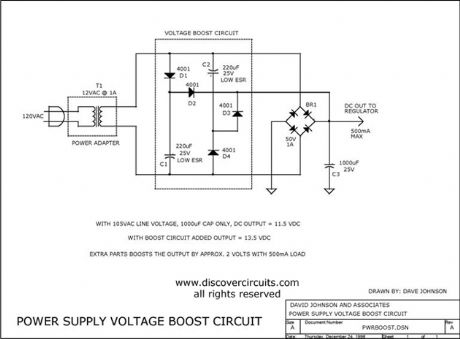
CAPS PROVIDE VOLTAGE BOOST TO SERIES REGULATORS
Published:2012/11/8 1:15:00 Author:muriel | Keyword: CAPS PROVIDE VOLTAGE , BOOST TO SERIES, REGULATORS
View full Circuit Diagram | Comments | Reading(796)
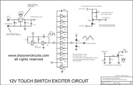
12V TOUCH SWITCH EXCITER CIRCUITS
Published:2012/11/8 1:12:00 Author:muriel | Keyword: 12V , TOUCH SWITCH, EXCITER CIRCUITS
View full Circuit Diagram | Comments | Reading(1045)
High Performance LED Flash Driver
Published:2012/11/8 1:10:00 Author:muriel | Keyword: High Performance, LED Flash, Driver
View full Circuit Diagram | Comments | Reading(778)
LD168 audio voltage-controlled flasher decorationcontrol circuit
Published:2012/11/7 19:25:00 Author:Ecco | Keyword: audio , voltage-controlled flasher, decorationcontrol circuit
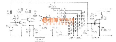
In the figure, LD168 is a tape recorders flasher ASIC for speaker sound level indication. It has four outputs which can directly drive a plurality of light-emitting diodes, and it can also drive lantern light emitting SCR devices.
(View)
View full Circuit Diagram | Comments | Reading(808)
5G167 audio voltage-controlled two-way water lantern control circuit
Published:2012/11/7 20:17:00 Author:Ecco | Keyword: audio, voltage-controlled , two-way water , lantern control
In the circuit shown in Figure, 5G167 is the recorders rotary lighting Speaker control ASIC produced by Shanghai elements factory 5; HTD is the sensor which can convert acoustic signal into a corresponding electrical signal.
(View)
View full Circuit Diagram | Comments | Reading(1201)
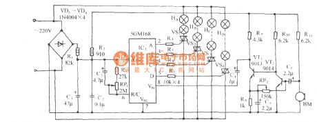
5GM168 audio voltage-controlled dance halls decorative lantern with birdsong sound circuit
Published:2012/11/7 20:14:00 Author:Ecco | Keyword: audio , voltage-controlled , dance halls , decorative lantern , birdsong sound
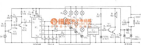
As shown in the figure, it uses the audio voltage-controlled lantern control integrated circuit 5GM168 as the core, and it is matched with birds sound and audio amp circuit to form the audio voltage-controlled lantern and birdsong sound circuit.
(View)
View full Circuit Diagram | Comments | Reading(740)
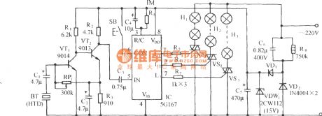
5GMl68 audio voltage-controlled holiday lights control circuit
Published:2012/11/7 20:11:00 Author:Ecco | Keyword: audio , voltage-controlled , holiday lights control
As shown in figure, it is a four-way lantern control circuit using 5GM168(chip's G- foot is vacant ), four-way outputs are added to the gate pole of VS1 ~ VS4 by current limiting resistor to control their on-off and light accordingly Road lanterns. BM is a pickup sensor.
(View)
View full Circuit Diagram | Comments | Reading(1070)
Single-phase motor reactor buck speed control Circuit
Published:2012/11/6 21:22:00 Author:Ecco | Keyword: Single-phase motor , reactor, buck, speed control
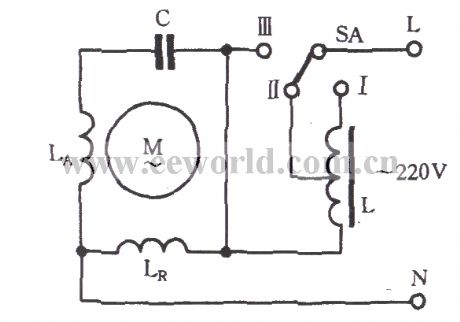
As shown in figure, the reactor is connected to the single-phase motor supply circuit in series, and the buck governor is realized by switching reactor coil tap. When the governor switch SA is set to the I , the main winding LR and reactor L is cascaded to power supply, the power supply voltage will be landed on the entire coil of the reactor L, and thus the voltage of main winding LR reduces, then the field generated by LR is weakening, the slip of the motor increases, the speed is significantly reduced; SA is set to Ⅲ , the main windingoperates under the rated voltage, the speed will be the highest; SA is set to II , it has the medium speed.
(View)
View full Circuit Diagram | Comments | Reading(1949)
| Pages:49/312 At 204142434445464748495051525354555657585960Under 20 |
Circuit Categories
power supply circuit
Amplifier Circuit
Basic Circuit
LED and Light Circuit
Sensor Circuit
Signal Processing
Electrical Equipment Circuit
Control Circuit
Remote Control Circuit
A/D-D/A Converter Circuit
Audio Circuit
Measuring and Test Circuit
Communication Circuit
Computer-Related Circuit
555 Circuit
Automotive Circuit
Repairing Circuit