
Control Circuit
Index 45
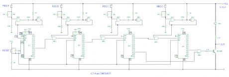
Digital Combination Lock
Published:2012/11/29 0:29:00 Author:muriel | Keyword: Digital Combination Lock
View full Circuit Diagram | Comments | Reading(882)
Electronic Doorbell with Counter
Published:2012/11/29 0:29:00 Author:muriel | Keyword: Electronic Doorbell, Counter
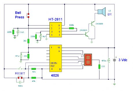
This circuit uses a synthesized sound chip from Holtek, the HT-2811. This reproduces the sound of a ding-dong chiming doorbell. Additionally, the circuit includes a CMOS 4026 counter display driver IC to count your visitors. (View)
View full Circuit Diagram | Comments | Reading(1298)
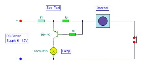
Doorbell Warning Switch
Published:2012/11/29 0:28:00 Author:muriel | Keyword: Doorbell Warning Switch
View full Circuit Diagram | Comments | Reading(729)
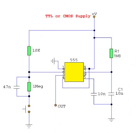
Switch De-Bouncer circuit
Published:2012/11/29 0:27:00 Author:muriel | Keyword: Switch De-Bouncer circuit
View full Circuit Diagram | Comments | Reading(762)
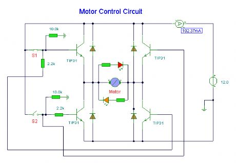
DC Motor Control
Published:2012/11/29 0:26:00 Author:muriel | Keyword: DC Motor Control
View full Circuit Diagram | Comments | Reading(0)
Electronic Door Release
Published:2012/11/29 0:25:00 Author:muriel | Keyword: Electronic Door Release
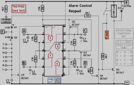
The IC is a quad 2 input AND gate, a CMOS 4081. These gates only produce a HIGH output, when BOTH the inputs are HIGH. When the key wired to 'E' is pressed, current through R1 and D1 switchs Q5 on.The relay energises; and Q5 is 'latched on' by R8. Thus, the Alarm is set by pressing a single key,say one of the two non-numeric symbols. (View)
View full Circuit Diagram | Comments | Reading(976)
Dark Activated Switch
Published:2012/11/29 0:24:00 Author:muriel | Keyword: Dark Activated Switch
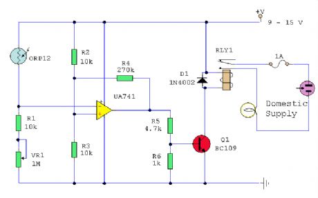
This circuit will activate a relay when light falls to a preset level. Light level can be adjusted with VR1 and the relay contacts may be used to operate an external light or buzzer. (View)
View full Circuit Diagram | Comments | Reading(1620)
Frost Alarm
Published:2012/11/29 0:24:00 Author:muriel | Keyword: Frost Alarm

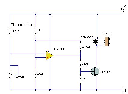
A simple thermistor triggered switch with adjustable threshold. It triggers with cold temperatures so may be used as a frost alarm or cold temperature switch. (View)
View full Circuit Diagram | Comments | Reading(1061)
Overvoltage Protection for the LM317
Published:2012/11/26 0:53:00 Author:muriel | Keyword: Overvoltage Protection, LM317
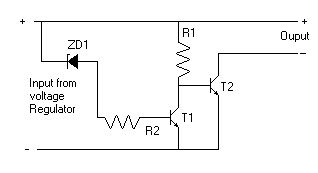
This is an add-on Over Voltage Circuit for the LM317 Regulator Circuit submitted by Matthew Hewson. (View)
View full Circuit Diagram | Comments | Reading(1171)
LM317 Voltage Regulator
Published:2012/11/26 0:51:00 Author:muriel | Keyword: LM317 , Voltage Regulator
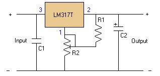
I constructed this voltage regulator to power my two way mobile radio from the car cigarette lighter circuit. It has many other uses and the voltage can easily be adjusted by the use of a potentiometer. The voltage regulator is an LM317T, and should accept up to about 14 volts without problems. It can handle up to 1 amp, but you WILL need a heatsink on the voltage regulator. (View)
View full Circuit Diagram | Comments | Reading(1582)
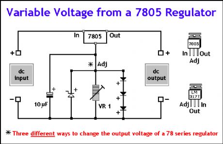
Variable Voltage Regulator
Published:2012/11/26 0:51:00 Author:muriel | Keyword: Variable Voltage , Regulator
View full Circuit Diagram | Comments | Reading(0)
Increasing Regulator Current
Published:2012/11/26 0:47:00 Author:muriel | Keyword: Increasing Regulator Current
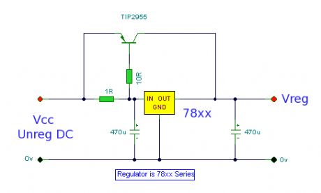
An outboard pass transistor used to increase the current output of a voltage regulator IC. (View)
View full Circuit Diagram | Comments | Reading(843)
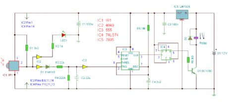
Automatic opening and closing curtain controller circuit
Published:2012/11/23 1:05:00 Author:Ecco | Keyword: Automatic opening , closing , curtain controller

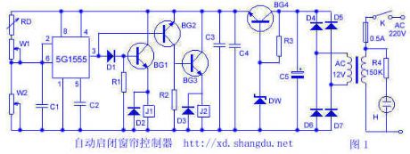

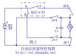
The controller can automatically identify the brightness of the room to make the curtains opening and closing with the best natural light. In Figure 1, photosensitive resistor RD and time base circuit 5G1555 form the brightness recognition part. when the it is black to a certain extent, photosensitive resistor RD's resistance increases, 5G1555 ② foot potential is less than 1/3Vcc ≈ 2.1V, ③ foot outputs a high potential, BG2 and BG3 are cut off, J2 releases. At the same time, D1, BG1 get conduction, J1 pulls in.
(View)
View full Circuit Diagram | Comments | Reading(1559)
Fuse Monitor Indicator
Published:2012/11/23 1:05:00 Author:muriel | Keyword: Fuse, Monitor, Indicator
The idea for this project may have come to me in a flash of inspiration, and its a very simple way to check if a fuse has blown without removing it from its holder. (View)
View full Circuit Diagram | Comments | Reading(901)
Refrigerator automatic protector
Published:2012/11/21 21:05:00 Author:Ecco | Keyword: Refrigerator, automatic protector


BT33 forms a delay circuit. When the power is turned on, the relay J1 does not work, contact J1-2 disconnects for five minutes, due to the charging voltage rise of the capacitor C1, BT33 gets conduction, relay J1 pulls, J1 -2 contact gets closure, then the refrigerator gets power, which is protected by J1-1 normally open contact. Under the case with normal voltage, D2, BG2 get conduction, D3, and D4, and BG3 are cutoff, relay J2 does not work.
(View)
View full Circuit Diagram | Comments | Reading(1992)
PWM Motor Control
Published:2012/11/21 2:15:00 Author:muriel | Keyword: PWM , Motor Control
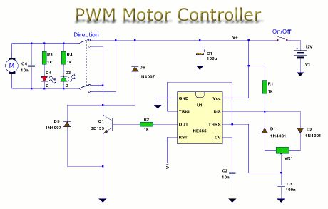
This is a circuit to control motor speed uses pulse width modulation (PWM). The PWM signal is generated by the ubiquitous 555 timer and output current amplified by a power transistor. (View)
View full Circuit Diagram | Comments | Reading(4249)
Constant Motor Speed Control
Published:2012/11/21 2:12:00 Author:muriel | Keyword: Constant Motor , Speed Control
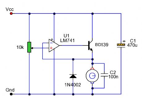
A simple op-amp feedback circuit designed to regulate the speed of a DC motor. (View)
View full Circuit Diagram | Comments | Reading(2733)
Curtain Control Circuit
Published:2012/11/21 2:07:00 Author:muriel | Keyword: Curtain, Control Circuit
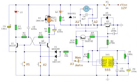
This hybrid circuit uses a mixture of transistors, an IC and a relay and is used to automatically open or close a pair of curtains. Using switch S3 also allows manual control, allowing for curtains to be left only partially open or closed. The circuit controls a motor which is attached to a simple pulley mechanism, to move the curtains. I first started this circuit over 20 years ago and apart from now using metal gears, very little has changed. (View)
View full Circuit Diagram | Comments | Reading(1362)
Model rocket launch controller
Published:2012/11/21 2:02:00 Author:muriel | Keyword: Model rocket , launch controller
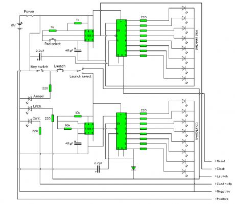

Most commercial rocket controllers available to buy are either expensive or do not have many features. After a lot of searching I found nothing that met my needs. I wanted a controller that could work multiple pads, as well as being easy to set up and pack away, so I designed my own. It has the ability to control up to 8 pads through a 6 core cable. You may want to be able to disconnect all your units. I used 6 pin DIN plugs so that all the units can be disconnected and easily transported. I wont go into details of how this works yet, although it is very useful as this type of cable is used in alarm systems and can be purchased cheaply. Each pad unit has a two sockets for signal input and output, with the input to the first pad unit coming from the controller. Any other units are then daisy chained to the first pad box. The controller also has a built in launch countdown controller, although this does have a bypass switch to use the controller in normal mode. On my controller I also added an accessory socket so that a large display can be connected to display the countdown sequence, although this is not included on the schematic to simplify the circuit. The main controller can also contain a rechargeable battery, although this does not have to be included. Not all features of my controller are shown on the circuit diagram, although you can easily add your own to suit your needs. (View)
View full Circuit Diagram | Comments | Reading(1471)
Infra Red Switch
Published:2012/11/21 2:00:00 Author:muriel | Keyword: Infra Red, Switch
This is a single channel (on / off) universal switch that may be used with any Infra Red remote control using 36-38kHz. (This is a very common remote handset frequency). In place of IR1 a TSOP1738 receiver may be used. (View)
View full Circuit Diagram | Comments | Reading(961)
| Pages:45/312 At 204142434445464748495051525354555657585960Under 20 |
Circuit Categories
power supply circuit
Amplifier Circuit
Basic Circuit
LED and Light Circuit
Sensor Circuit
Signal Processing
Electrical Equipment Circuit
Control Circuit
Remote Control Circuit
A/D-D/A Converter Circuit
Audio Circuit
Measuring and Test Circuit
Communication Circuit
Computer-Related Circuit
555 Circuit
Automotive Circuit
Repairing Circuit