
Control Circuit
Index 57
Automatic parking light switch circuit
Published:2012/9/27 21:30:00 Author:muriel | Keyword: Automatic, parking light, switch
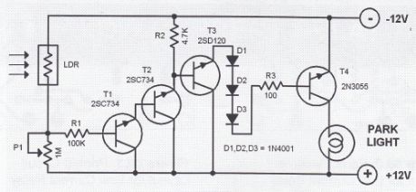
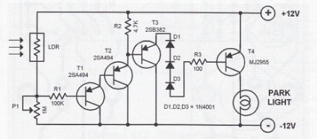
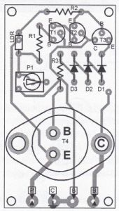
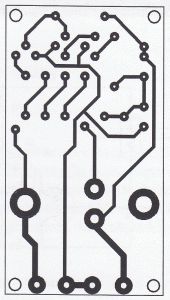
This automatic park light switch with LDR automatically turn ON the light when the surrounding light dims to a preset level. The first circuit diagram is an NPN design intended for negative grounded chassis. The second diagram is the PNP version intended for a positive grounded chasis.The dim level at which the circuit activates is set through the potentiometer P1.The printed circuit board layout can be used for both the negative and positive polarity chassis. Take note that the transistors and different for each chassis type. The connectors labeled in the parts placement diagram have the following connections:P = Power live of the carC = Car chassisB = Park light bulb
Automatic Park Light Switch Positive Ground
Automatic Park Light Switch Negative Ground
Parts Placement
Printed Circuit Board Layout
(View)
View full Circuit Diagram | Comments | Reading(1848)
Refrigerator Alarm Circuit
Published:2012/9/27 21:29:00 Author:muriel | Keyword: Refrigerator, Alarm Circuit
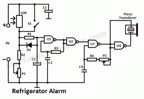
Use this refrigerator alarm circuit to prevent leaving the fridge door open by sending out an alarm signal every time the door is left open for some time.The sensor of the alarm is an LDR. After a short delay, it triggers an alarm signal and keep the signal on until the door is shut close.When the light falls on the LDR, it becomes low ohmic. The voltage at the junction of LDR/R2 charges the C2 via the R1 slowly. After about 10 seconds, the capacitor voltage reaches the input threshold of U1. Then U1 generates a square wave signal with a frequency of several Hertz. The time delay can be shortened by decreasing the value of R1 down to 220KΩ. U2 inverts the signal from U1. This inverted signal switches the U3 tone oscillator. When there is no light hitting the LDR, U3 is turned off. Finally, U4 amplifies the tone signal generated by U2 and drives the ceramic transducer. The frequency is doubled at the transducer.
The light sensitivity of the LDR can be adjusted with P1. The alarm tone freq. can be adjusted to the resonant freq. of the ceramic transducer through P2.
The maximum volume level can be reached when the tone freq. is equal to the ceramic transducer’s resonant freq..
The refrigerator alarm circuit can be powered with a small 9 volts battery. The current consumption is around 0.6 mA at standby and 5 mA when the alarm is activated.
Refrigerator Door Alarm circuit diagram
(View)
View full Circuit Diagram | Comments | Reading(2026)
Bike Guard Alarm Circuit
Published:2012/9/27 21:25:00 Author:muriel | Keyword: Bike Guard, Alarm Circuit
This Simple circuit can be used to Guard your bike from theft. It gives a loud alarm tone if somebody tries to start the bike. The alarm disables only when the hide switch S2 is opened. The circuit has little component count and can be easily fixed in the bike.Working of the circuit is simple. The alarm generator buzzer or Horn is activated by an SCR and its triggering is under the control of the transistor T1. In the Armed position, Switch S2 is closed and S1 (Key switch of the bike) is opened. In this state, T1 will not conduct and SCR and Buzzer remains idle in armed position. When somebody turns on the Key switch of the Bike using a duplicate key, Capacitor C1 charges through R1, D1 and R2. It will take a time delay of few minutes to attain full charge in C1. When C1 fully charges T1 conducts and triggers the SCR. Buzzer connected to the Anode of SCR gets electrical path and it sounds the alarm. LED also lights to indicate the theft. The time delay is added through C1 so that the alarm will sound only after the bike is started .This aborts the attempt of theft.
Bike Guard Alarm Circuit diagram
The unit should hide in a place like the Carrier Box. So that switch S2 can be protected. An additional bike horn can be connected in the place of the buzzer to get loud sound. Connection point from R1 should go to the key switch point that goes to the engine so that; the unit will be activated only if the key switch is closed. Time delay can be changed by changing the value of C1 or R2. Hide switch S2 should be kept closed for arming the bike only after removing the switch key. Power to the circuit is obtained from the 6/12 volt bike battery. High current type transistor T1 and SCR are used to handle the high power of bike battery.Use 1 watt resistors to handle high power.Note: This circuit is not sufficient if the tricky thief knows some electronics. (View)
View full Circuit Diagram | Comments | Reading(1345)
Anti-theft Car Alarm circuit
Published:2012/9/27 21:23:00 Author:muriel | Keyword: Anti-theft, Car Alarm
Here is a simple Anti theft car alarm device for your Car. It generates a loud alarm when there is an attempt of theft. When the intruder opens the door, the circuit senses the attempt of theft and after 2 minutes, the alarm will be activated. The time delay is provided to help the user to leave the car after arming with the deviceThe anti theft alarm circuit taps power supply from the car battery. Switch S1 is the on/ off switch of the alarm circuit. When the circuit is activated through S1, the flashing LED blinks indicating that the car is armed. But the alarm generator works only if the Dome lamp of the car is switched on through the door switch. This switch turns on the dome lamp, if any one of the door is opened. The user can put S1 in the on position before leaving the car.
There will be a delay of 2 minutes so that the alarm will not be generated. When the intruder opens the door, Diode D1 forward biases and capacitor C1 charges through R1. It takes around 1 minute to charge C1. When C1 fully charges, the 12 volt Zener conducts to trigger the NPN transistor T1.Zener diode switch is provided to avoid false triggering and T1 conducts only when C1 charges fully. When T1 conducts C2 charges and the voltage in C2 triggers the gate of SCR. The Horn connected to the Anode of the SCR sounds indicating the theft. The horn can be either a spare car horn or a Hooter that gives loud alarm.
Anti-theft Car Alarm Circuit diagram
Note: Before leaving the car, switch on S1 and after entering the car switch off S1. Hide S1 in a place that cannot be detected. (View)
View full Circuit Diagram | Comments | Reading(1259)
DIY LDR Switch Circuits
Published:2012/9/27 21:22:00 Author:muriel | Keyword: LDR Switch

Here are some DIY LDR switch circuits available on our website and the web. LDR switches are used to switch a relay or other device when light are present or absent. LDRs or Light Dependent Resistors are very useful especially in light/dark sensor circuits.
Normally the resistance of an LDR is very high, sometimes as high as 1000 000 ohms, but when they are illuminated with light resistance drops dramatically.
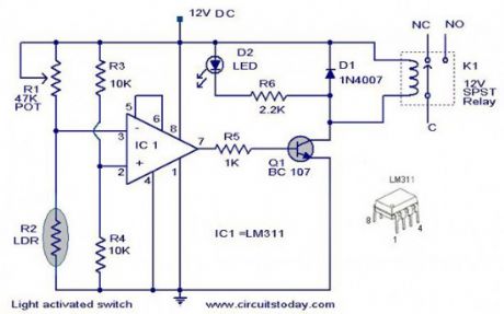
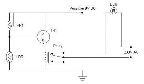
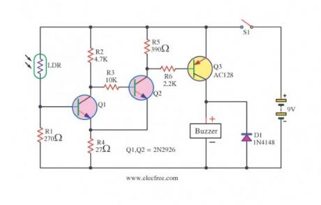
LDR switch circuit diagrams
This is a light switch or light activated relay circuit. The relay on when LDR uncoverd and relay off when LDR covered. Adjust VR1 for light sensitive. LED will turn on at the same time with relay.Source: http://www.coolcircuit.com/circuit/light_switch/
This is the circuit diagram of a light activated switch based on National Semiconductors comparator IC LM 311 and a LDR.Source: http://www.circuitstoday.com/light-activated-switch-circuit
Light sensitive switch with LDR, actually it has a buzzer which will sound an alarm…Source: http://www.eleccircuit.com/light-sensitive-switch-with-ldr-2n2926/
(View)
View full Circuit Diagram | Comments | Reading(3712)
Processor Fan Controller circuit
Published:2012/9/26 21:35:00 Author:muriel | Keyword: Processor, Fan, Controller
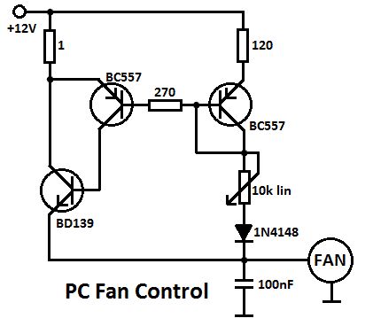
This Processor Fan Control circuit is intended to be used with relatively old PCs, since more recent models generally have a fan control circuit already integrated into the motherboard. These controllers ensure that the amount of cooling is increased if the processor becomes too warm and decreased if the processor temperature is relatively low. The circuit described here consists of only a handful of components, which you will probably already have in a drawer some-where. Transistors T1 and T2 are driven into conduction by the base current ?owing to the fan via P1 and D1. There will always be a current ?owing through R1, and it will be approximately 120 times as large as the current through R2. R3 has been added to prevent the base current of T2 from becoming too large when P2 is set to its minimum resistance. D1 ensures that even at this extreme setting, the voltage on the base-emitter junction of T3 will still be large enough to allow it to conduct.
Processor Fan Control Diagram
(View)
View full Circuit Diagram | Comments | Reading(2261)
Flame Failure Monitor
Published:2012/9/26 21:16:00 Author:muriel | Keyword: Flame Failure, Monitor
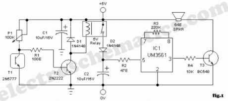
A minimum amount of hardware is needed to build a simple flame or fire failure monitor that enables you to monitor the status of the flame in a chamber/furnace. Owing to its integrated alarm generator, the interface can be easily adapted for use with a wide range of light/heat sensors. Here a readily available photo transistor 2N5777 (T1) works as the flame sensor. The 5V regulated dc supply for this circuit can be derived from a 12 V mains adaptor or a 9V rechargeable battery. In the presence of the flame, T1 conducts (resistance low) and most of the base current of relay driver transistor T2 find an alternative easy path via T1. As a result T2 remains cutoff. If flame is absent, T1 behaves almost an open circuit, and the current through P1 and R1 flows into the transistor’s (T2) base.
Next, the 5V reed relay is energised and 5V positive supply is extended to the alarm generator circuit built around the siren generator UM3561(IC1). Output signals from IC1 is amplified by transistor T2 to drive a standard 64 Ohm 1W mylar speaker.
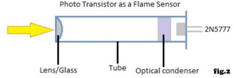
For optimum perfomance, enclose phototransistor (T1) in a suitable long tube and add an optical assembly (see fig.2). The adjustment of sensitivity set preset pot P1 is also very critical.
Flame (fire) Monitor Circuit Diagram
(View)
View full Circuit Diagram | Comments | Reading(1237)
Sound Controlled Toggle Switch
Published:2012/9/26 21:16:00 Author:muriel | Keyword: Sound Controlled, Toggle Switch
Here is a simple toggle switch that can be operated through sound signals such as whistle or clap. The output of the toggle remains either low or high until the microphone senses the next sound signal. The circuit is too sensitive and can be used to control AC loads through the relay.The sound signal received by the condenser mic will be amplified by IC1. TL071 is the high gain Operational Amplifier used in the preamplifier section of radio and tape recorder. The amplified output is used to control the JK Flip Flop IC CD4027 designed in the toggle mode. When the clock input pin 14 of IC2 gets a low to high pulse from IC1, its output turns high and remains as such. When the next pulse arrives, the output of IC2 turns low. In this way it functions as a toggle switch. Variable resistor VR adjusts the sensitivity of MIC at the particular sound level. Relay driver T1 can be used to operate the relay.
Sound Controlled Toggle Switch
(View)
View full Circuit Diagram | Comments | Reading(723)
Small power DC motor control component KCZ1 electrical schematic diagram and external wiring
Published:2012/9/25 22:08:00 Author:Ecco | Keyword: Small power, DC motor, control component , electrical schematic, external wiring
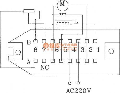
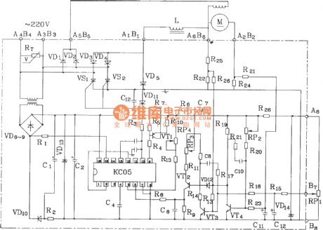
KCZ1 small power DC motor control components are suitable for small power DC motor speed control with 200V rated voltage, and it has negative feedback voltage and excitation output, and the components have small size and good speed regulation performance. The components can also be used as a DC power supply.The electrical parameters are shown as following:Grid voltage: (220 ± 10)%.Rated output voltage: DC 200V.Rated output current: 5A, the largest value is 9A (< 10ms ).Output excitation voltage: DC 220V.Output excitation current: 0.5A.External speed potentiometer : 2.2k12 multi-turn potentiometer.Speed ratio: up to 20:1.Allowing ambient temperature: - l0 ~~ +50 ℃.
(View)
View full Circuit Diagram | Comments | Reading(4858)
Car Battery Monitor 12 Volt
Published:2012/9/25 21:48:00 Author:muriel | Keyword: Car Battery, Monitor, 12 Volt
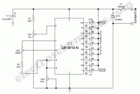

Here is an interesting Car Battery Monitor circuit of a low power electronic dc voltmeter circuit that can be used with car electric systems that run on 12 volt batteries. The voltmeter is an expanded scale type that indicates small voltage steps over the 10 to 16 volt range for 12 volt batteries.At the heart of the circuit is a ubiquitous dot-bar volt meter LM3914N (IC1). This IC is operated in the expanded-scale mode so that the circuit responds in the 10-16V range. IC1 outputs a steady voltage on pin 7 from the internal voltage reference. This is fed via voltage dividers VR2and R2 to the internal reference input pins(4&8) to set the range that the meter is sensitive to. The measured voltage is fed in on pin 5 via the voltage divider consisting of R1 and VR1. This divider scales the input voltage down to a range that is useful to IC1.
Car Battery Monitor schematic for 12V batteries
It is possible to set the meter to read equal steps across a variety of upper and lower voltages. Different colored LEDs can be used for the voltage level indicators(D1-D10). It will be necessary to have an adjustable regulated DC lab power supply and a good quality digital volt meter (DVM) to perform the calibration. Connect the external volt meter across pins 6 and 4 of IC1 and adjust VR2 for a reading of 1.2 volts. Center the settings of VR1 and VR3. If the span between the end points of VR1 is 4.5V, the circuit is ready to use as a 10.5 to 15V scale battery monitor. (View)
View full Circuit Diagram | Comments | Reading(1474)
Cashbox or Locker Alarm
Published:2012/9/25 21:48:00 Author:muriel | Keyword: Cashbox, Locker, Alarm circuit
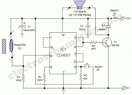
The locker alarm circuit or cashbox watcher can be used to protect a cashbox/locker from unauthorised access. This tried and tested design forms a fool-proof,remotely operated alarm/electromagnetic relay driver that receives its control signal from a standard reed switch. The circuit works off a 12V dc power supply.After construction, enclose the whole circuit, including the power supply (preferably with a backup facility) in a tamper proof metallic box and keep it in a secure location. For optimum safety, use key lock type switches for power (S3) and reset(S2) control. Now open your cashbox/locker and fix a strong permanent magnet in its door and the reed switch(S1) in the door frame so that when door is closed, the magnet is very near to S1. Now connect the terminals of reed switch to the input of the main circuit using a strong two-core cable.Operation of the locker alarm circuit, built around CD4001(IC1) is straight forward. When switch S3 is turned to ON state,the 12V supply is extended to the whole circuit.Normally, when cashbox/locker is closed, the reed switch is also closed due to the presence of bar magnet and hence the the output (at pin 10) of IC1 (Quad 2-input NOR gate pack) is in logic low state.When the cashbox/locker is opened, reed switch also opened and the output state changes to logic high level to enable the bistable latch realised using next two NOR gates (Final NOR gate is not used here). As a result, driver transistor (T1) activates to drive the output load. A ready made 12V electronic hooter or a standard 12V electromagnetic relay can be used as the output load. Push-to-on type switch (S2) is the reset switch for the bistable circuit.
Locker Alarm Circuit Diagram/Schematic
(View)
View full Circuit Diagram | Comments | Reading(2393)
Adjustable Timer circuit 1-10 minute
Published:2012/9/25 21:47:00 Author:muriel | Keyword: Adjustable, Timer circuit, 1-10 minute
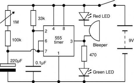
The Adjustable Timer circuit starts timing when switched on. The green LED lights to show that timing is in progress. When the time period is over the green LED turns off, the red LED turns on and the bleeper sounds. The time period is set by adjusting the variable resistor. It can be adjusted from 1 to 10 minutes (approximately) with the parts shown in the diagram. You can mark the times on a scale drawn on the box.Please note that the range of time periods is only approximate. With perfect components the maximum time period should be 4? minutes, but this is typically extended to about 10 minutes because the 220μF timing capacitor slowly leaks charge. This is a problem with all electrolytic capacitors, but some leak more than others. In addition the actual value of electrolytic capacitors can vary by as much as ±30% of their rated value.
Adjustable 10 minute timer schematic
(View)
View full Circuit Diagram | Comments | Reading(2030)
Tilt Sensor Alarm Circuit
Published:2012/9/25 21:45:00 Author:muriel | Keyword: Tilt, Sensor Alarm
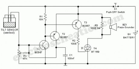
Ultra simple circuit of the tilt sensor alarm presented here can be fabricated using readily available inexpensive components. The circuit is a true transistor based design. Home made Tilt sensor for this circuit is an ordinary little glass/plastic bottle with two metal needles inserted through its cap, and a small quantity of water inside.You can also try your own ideas to make the tilt sensor. A 9V alkaline battery is enough for powering the whole circuit.
Tilt Sensor Circuit Schematic
Usually, transistor T1 is in inactive state. When the sensor assembly is tilted, both needles inside the sensor (bottle) are short circuited by the water and a positive voltage is available at the base of T1 and it becomes active. Activation of T1 causes the activation of next transistors T2 and T3. After this, T2 supplies constant bias for T1 to make it latched and T3 triggers the SCR(T4) which inturn energises the active piezo-sounder(BZ1). Once activated the circuit can be deactivated by depressing the power/reset switch S1.
Preset pot P1 is deliberately added here to adjust the circuit sensitivity. This may become necessary if you are trying a different (readymade) tilt sensor. Similarly,SCR(T4) and piezosounder (BZ1) may be replaced with near equivalent parts. Resistor R3 (100-150 Ohm) is optional. (View)
View full Circuit Diagram | Comments | Reading(1482)
Door Timer Circuit with Alarm
Published:2012/9/25 21:42:00 Author:muriel | Keyword: Door Timer, Alarm circuit
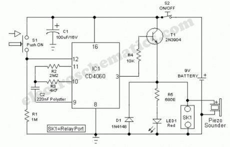
We are in a digital era! Now we can add some intelligence to our doors and gates without too much investments. Just assemble this little door timer circuit built around a few cheap and simple components and link it to any door/gate as per your requirement and taste. If the door/gate remains in open condition for a prefixed time an acoustic sounder starts beeping to raise an alert. Enough?At the heart of the circuit is CD4060, which is a 14-stage ripple-carry binary counter/divider plus oscillator. Here CD4060 is configured as an independent timer. In standy by state, ie when switch S1 is in closed condition, the reset terminal ( pin12) of CD4060 is at a high level and the timer is in inactive mode. When the door is opened, S1 also opened as per the mechanical arrangement and CD4060 gets activated.After a short period,transistor T1 conducts to power the active piezo-sounder. Red LED in parallel with the piezo-buzzer also lights up instantly. When the door(and hence S1) is closed, circuit returns to standby state automatically.The open door alarm circuit works off 9V (PP3/6F22) battery supply. Assemble the circuit on a small PCB and enclose in a plastic box of appropriate size. Mount the switch S1 in the door/gate frame and connect it to the circuit through external cable. If possible use a key-lock type switch for power on/off function (S2).
Note: Preset delay time can be changed by changing the value of timing resistor R3. SK1 is an optimised connection terminal for attaching a standard 6-9Volt electromagnetic relay.
Door Timer Circuit Schematic
(View)
View full Circuit Diagram | Comments | Reading(1405)
Motion Sensor Switch for alarm, light or water sprinkler
Published:2012/9/25 21:42:00 Author:muriel | Keyword: Motion Sensor, Switch, alarm, light, water sprinkler

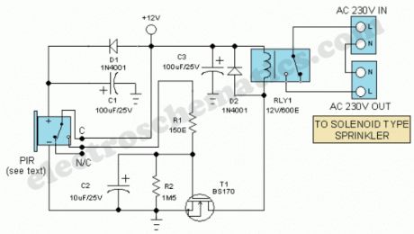
The Motion Sensor Switch circuit is a motion sensor controlled automatic water sprinkler but you can easily add an alarm/light function too. Before beginning the construction contact your nearest electronics component vendor and procure a readymade box-type Passive Infrared (PIR) Motion Sensor unit. Such units, packed in a compact enclosure with power input and relay output terminals are widely available. In prototype, an unbranded (Made in China) PIR Motion sensor with the following specifications are used.
Detection Range:10Meter Maximum
Supply Input:12V DC, <500mA
Relay Output :Common(C),Normally Closed(N/C),Normally Opened(N/O)
Relay ON time: 15 Secs (Not Adjustable)
Now install the PIR module hanging from a 3 metre high mast (to cover 10 metre radius area) and connect its supply and relay terminals to our finished and enclosed circuit, observing right polarity. A 4-core screened cable can be used for this interconnection. Power the circuit from a regulated 12VDC adaptor/solar power box.
Whenever the PIR module detect movement of a live body its relay output toggles and the switching mosfet (T1) in the circuit is switched to on via resistor R1 and related parts. As as result, the EM relay at the output of T1 is activated and the electric sprinkler gets its supply through the relay (RLY1) contacts. This contacts (or spare contacts) can also be used to activate a high-power warning alarm.
Motion Sensor Switch Circuit Schematic
(View)
View full Circuit Diagram | Comments | Reading(4364)
Electronic GateKeeper circuit
Published:2012/9/25 21:41:00 Author:muriel | Keyword: Electronic GateKeeper
This circuit can do the job of a Gatekeeper and intimates you if someone passes through the gate. The alarm can be an AC bell or a Lamp. The alarm turns on for 1 minute and stops if the light barrier is restored again.Infrared rays are used as the light barrier to activate the alarm system based on a Phototransistor. The high gain NPN Darlington phototransistor L14F1 conducts when its face is illuminated with IR rays. This brings its collector to ground potential. IC1 is used as a simple voltage comparator with a potential divider R2 and R3 connected to its inverting input. So that half supply voltage (6 volts) is available to its inverting input. Its non inverting input is connected to the collector of the phototransistor. Normally the output of IC1 will be low since T1 is conducting. When the IR beam breaks, the collector of T1 becomes high and the voltage at the non inverting input of IC1 increases above the voltage at the inverting input and output becomes high. This triggers the relay driver T2 and relay turns on. Capacitor C1 gives a short delay at the non inverting input of IC1 to prevent false triggering. Capacitor C2 keeps the base of T2 high for a short time even if the IR rays restore.
Electronic Gate Keeper Schematics
(View)
View full Circuit Diagram | Comments | Reading(836)
7805 Regulator IC Circuits
Published:2012/9/25 21:33:00 Author:muriel | Keyword: Regulator
Fixed voltage Positive and Negative regulator ICs are used in circuits to give precise regulated voltage.78 XX series regulator IC can handle maximum 1 ampere current. The Regulator ICs require minimum 1.5 higher input voltage than their voltage rating. For example 7805 IC requires minimum 6.5 volts to give 5 volt output. Here are some circuit designs of IC 7805 to monitor the output voltage.1.This is the manipulation of the Regulator IC 7805 to give 9 volt regulated output. Normally the pin2 of the regulator IC is connected to the ground. Here it is connected to a 3.9 volt Zener diode. So the output from the Regulator IC will be 9 volts.
7805 Circuit 12. This circuit can tell whether the IC 7805 is giving output or not. IC 7805 requires minimum 6.5 volt input to give 5 volt regulated output. When the input voltage is above 6.5 volts, Zener conducts and LED turns on indicating sufficient input voltage. Diffuse type Red LED requires 1.8 volts and Zener 4.7 volts .So to activate both these, input voltage should be minimum 6.5 volts. If the input voltage drops below 6.5 volts, Zener cutoff and LED turns off. This indicates the zero output from the regulator IC.
7805 Circuit 2
3. This is a simple LED monitor to tell the output voltage from 7805. If the input voltage is above 6.5 volts, LED shows full brightness. When the input voltage reduces below 6.5 volts, brightness of LED decreases.
7805 Circuit 3
(View)
View full Circuit Diagram | Comments | Reading(996)
Security Light & Switch with PIR Sensor
Published:2012/9/25 21:31:00 Author:muriel | Keyword: Security, Light, Switch, PIR Sensor
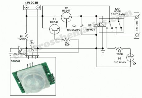
SB0061 is a pyroelectric sensor module,developed for human body detection. A PIR detector combined with a fresnel lens are mounted on a compact size PCB together with an analog IC (SB0061) and limited components to form the module. High level output (3.3V) of pre-settable variable width (5Secs -18 Minutes) is provided.
Circuit diagram of the PIR Motion Sensor Light and Switch based on SB0061 shown here can be used for security or corridor lighting in power saving mode. The 12V DC supply required for the whole circuit can be fed from any standard 12V ac mains adaptor/battery.
Working of the circuit is simple and straight forward. When any movement is detected within near 5-6 metres, around 3.3 Volt is appeared at the base of Transistor T1 and it conducts to fire the next relay driver transistor T2. As a result, the 12V DPDT relay is energised to power the White LED through current limiting resistor R3. Spare relay contacts can be used as a switch to control any suitable external load. The white LED and the relay remains ON for a duration based on the mono time setting in SB0061, ie from 5 Secs to 18 Minutes.
PIR Motion Sensor Circuit Schematic
(View)
View full Circuit Diagram | Comments | Reading(3985)
Power switch with infrared proximity sensor
Published:2012/9/25 1:04:00 Author:muriel | Keyword: Power switch,infrared,proximity sensor
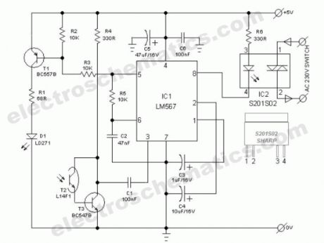

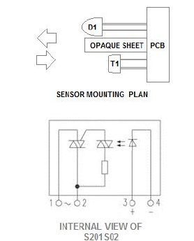
The power switch with infrared proximity sensor is intended for the recognition of obstructions at distances of a few millimetres to a few centimetres. This compact sensor switch can be used to open a water tap via a solenoid valve. In our circuit, the proximity sensor assembly is built from a discrete infrared light emiting diode (LD271-from Siemens/Osram) and a phototransitor (L14F1). A solid-state relay (S201S02-from Sharp) at the output of the circuit enables larger ac mains operated loads (for instance, the solenoid valve) to be switched.
How the infrared switch is working
At the heart the circuit is one renowned phase locked loop tone decoder chip (LM567 from NSC). When the pulsed infrared light signal from D1 is reflected by a nearby object, phototransistor T2 -through T3- provides a signal to pin 3 of IC1. If the signal frequency lies within the same band as that of the internal generator, output terminal (pin8) of IC1 is connected to earth, where upon LED in the solid-state relay (IC2) lights and the relay is energised.
Infrared Power Switch Circuit Diagram
Infrared proximity sensor compornents and parts
(View)
View full Circuit Diagram | Comments | Reading(1918)
Humidity Control Switch circuit
Published:2012/9/25 0:47:00 Author:muriel | Keyword: Humidity Control,Switch
This humidity controlled switch circuit turns on and off an electrical load (for example a heater) depending on the moisture content of the surrounding air. The moisture is “sensed” with the help of a plate capacitor C2. This capacitor is similar to the old air dielectric plate capacitors in your vintage AM radio. It uses 2 ICs: LM358 and 4001.How does the humidity controlled switch works
At a certain humidity level, the circuit switches on the load. The moisture level is converted to a voltage through R3 in the first part of the circuit.The first opamp A1 functions as a high impedance. The second opamp A2 functions as a comparator with a hysteresis of about 15%.
The variable scale of the potentiometer P1 produces voltages from 0.6V to 3 volts and proportional to moisture levels from 20 to 100%. The P1 therefore sets the moisture level where the circuit activates. Once the moisture level reaches above the set level, the triac TR1 triggers and the attached load (heater) turns on.
The current consumption of the circuit is around 13 mA while activated. If you use it to control a heater, you can plug in two 100 watt bulbs. If you use light bulbs as heating element, enclose them in a metal container.
Moisture Controlled Switch Circuit Schematic
(View)
View full Circuit Diagram | Comments | Reading(1287)
| Pages:57/312 At 204142434445464748495051525354555657585960Under 20 |
Circuit Categories
power supply circuit
Amplifier Circuit
Basic Circuit
LED and Light Circuit
Sensor Circuit
Signal Processing
Electrical Equipment Circuit
Control Circuit
Remote Control Circuit
A/D-D/A Converter Circuit
Audio Circuit
Measuring and Test Circuit
Communication Circuit
Computer-Related Circuit
555 Circuit
Automotive Circuit
Repairing Circuit