
Control Circuit
Index 60
Car Wiper-Speed Controller
Published:2012/9/13 21:22:00 Author:Ecco | Keyword: Car, Wiper-Speed Controller
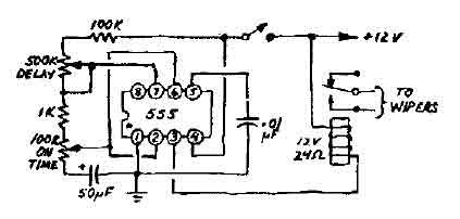
This 12V wiper speed controller circuit uses the 555 timer. And can be fitted to any car. Its one of those very easy and usefull circuits! (View)
View full Circuit Diagram | Comments | Reading(2729)
IR Motion Detector alarm
Published:2012/9/13 21:22:00 Author:Ecco | Keyword: IR Motion Detector , alarm
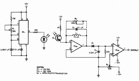
This type of motion detector uses the same basic concept as the active infrared motion detector. An interruption in a 5 kHz modulated pulsating beam that is transmitted by an infrared diode and received by an infrared transistor sets off the alarm.
Source: NEXT.GR (View)
View full Circuit Diagram | Comments | Reading(1767)
Voice-activated automatic light accompanied music sound circuit using SK-IV
Published:2012/9/12 22:42:00 Author:Ecco | Keyword: Voice-activated, automatic light , accompanied music sound
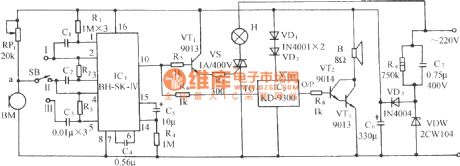
The circuit is shown in Figure, and it includes acoustic transducer, voice control circuit, SCR control circuit, music sound circuit and AC buck rectifier circuit. BH-SK-IV is the core device of the circuit.
(View)
View full Circuit Diagram | Comments | Reading(1220)
Vice control music outlet circuit using SL517A
Published:2012/9/12 22:29:00 Author:Ecco | Keyword: Vice control, music outlet
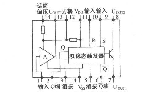
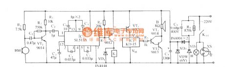
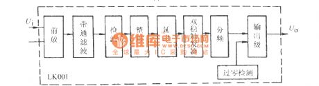
The circuit is shown in Figure, and it is composed of acoustic sensor, voice control IC, relay control circuit, song voice circuit and AC buck rectifier circuit. Voice control IC uses SL517A which contains high-gain amplifier, bistable flip-flop and buffer output level, and it has two packages of dual in-line and black ointment. Its internal functional block diagram is shown as below.
(View)
View full Circuit Diagram | Comments | Reading(1006)
Multifunction fans with birdsong control circuit using LC902
Published:2012/9/12 22:55:00 Author:Ecco | Keyword: Multifunction fans , birdsong control
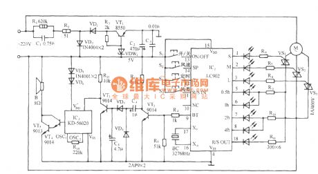
The circuit is shown as the figure. The core device of fan control circuit is LC902 which is the LC901 's improved device, and compared with LC901, LC902 increases sleeping wind output and key audio output.
(View)
View full Circuit Diagram | Comments | Reading(976)
The frequency-selecting voice control music outlet circuit with LK001
Published:2012/9/12 22:51:00 Author:Ecco | Keyword: frequency-selecting , voice control , music outlet
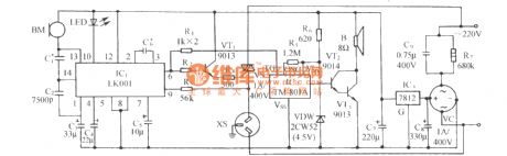
The circuit is shown as the figure. It includes acoustic sensor BM, voice control integrated circuit, SCR control circuit, imitation sound circuit and AC buck rectifier circuit and so on . Voice control ASIC LK001 is the core component of the control circuit, its internal circuit functional block diagram is shown in the following figure.
(View)
View full Circuit Diagram | Comments | Reading(1125)
Natural wind fan control circuit with cricket sounds
Published:2012/9/12 22:48:00 Author:Ecco | Keyword: Natural wind, fan control , cricket sounds

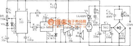
The circuit is shown as the figure. It includes multivibrator circuit, SCR control circuit, voice sound circuit, audio amplifier circuit and AC buck rectifier circuit. It enables fans to send natural wind with varying soft wind power and accompanied by autumnal cricket sounds. Time-base circuit 555 and R1 , RP1 , VD1, VD2 , C2 form a low-frequency multivibrator with adjustable duty cycle, and the oscillation frequency is:
(View)
View full Circuit Diagram | Comments | Reading(1327)
Acousto-Optic dual-controlled high - power lantern accompanied by birdsong circuit using SH805
Published:2012/9/13 2:02:00 Author:Ecco | Keyword: Acousto-Optic, dual- controlled , high - power , lantern , accompanied by birdsong
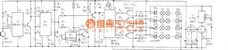
As shown in the diagram, the circuit consists of voice control circuit, Acousto-Optic dual control monostable timing circuit, SH805 lighting control circuit, birdsong voice circuit and AC buck rectifier circuit and other components. It can realize manual or automatic control of four high-power lantern with 16 kinds lantern patterns changing, but also sending sweet birdsong. BM is sound energy sensor; BH-SK-I is the voice control ASIC.
(View)
View full Circuit Diagram | Comments | Reading(818)
Computer room temperature control circuit using TC620 temperature sensor
Published:2012/9/13 1:44:00 Author:Ecco | Keyword: Computer room , temperature control , temperature sensor
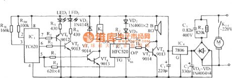
As shown in the figure, the circuit consists of the temperature sensor, control devices, the upper and lower temperature display, relay control motor circuit, waves analog voice circuit and AC buck rectifier circuit.
(View)
View full Circuit Diagram | Comments | Reading(1699)
Temperature Controller with U217B
Published:2012/9/12 21:09:00 Author:Ecco | Keyword: Temperature Controller
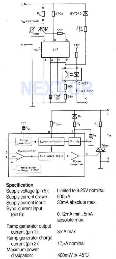
A triac controller for switching resistive loads directly from the mains supply using the zero crossing technique. The device is powered directly from the mains via a diode and dropper resistor, and the IC has its own regulator to limit its supply to 9.25V. To ensure that no switching occurs outside of the zero crossing point, full wave logic is employed to guarantee that complete mains cycles only are switched to the load.
Source: NEXT.GR (View)
View full Circuit Diagram | Comments | Reading(1617)
Fast charge Controller with MAX712 / MAX713
Published:2012/9/12 21:07:00 Author:Ecco | Keyword: Fast charge Controller
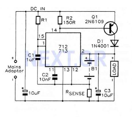
The MAX712 and MAX713 are nickel cadmium (Ni-Cd) battery fast charge controllers which will fast charge batteries from a DC source at least 1V higher than the maximum battery voltage. 1 to 16 series cells can be charged at rates up to 4C. A voltage-slope detecting analogue-to-digital converter, timer, and temperature window comparator determine charge completion. The MAX712 or 713 are powered by the DC source via an on-clip +5V shunt regulator, and draw a maximum of 5uA from the battery when not charging. A low-side current-sense resistor allows the battery charge current to be regulated while still supplying the power to the battery's load.
Source: NEXT.GR (View)
View full Circuit Diagram | Comments | Reading(2521)
Voltage Controlled Filter SSM2044P
Published:2012/9/12 21:01:00 Author:Ecco | Keyword: Voltage Controlled Filter
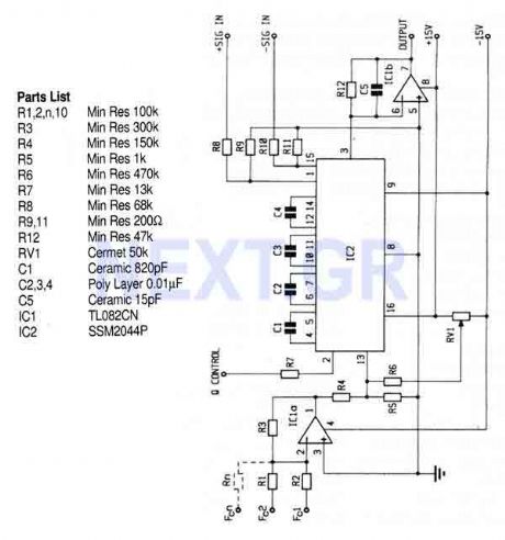
At this circuit the SSM2044 IC is used, a 4 pole voltage controlled filter designed for electronic music applications. On-chip voltage control of resonance allows direct and easy interfacing with programmers and controllers. The IC features extended control range, low noise, and high control rejection. The filter can also be used as a low distortion sinewave oscillator.
Source: NEXT.GR (View)
View full Circuit Diagram | Comments | Reading(1267)
Speech Pitch Controller (MSM6322GSK)
Published:2012/9/12 20:56:00 Author:Ecco | Keyword: Speech Pitch, Controller
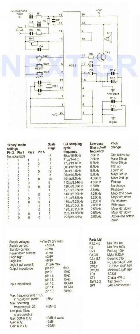
That circuit uses the MSM6322GSK which is only available in small 24 pin plastic SOP style package. A speech pitch converter IC that operates in real time and requires very few external components. It has a microphone preamplifier and line level input and the output requires only a single transistor to directly drive a loudspeaker. As well as the microphone preamplifier, the IC contains a 4th order low pass filter on input and a 3rd order low pass filter on output. In addition there is a build-in 8-bit A/D converter and 9-bit D/A converter.
Source: NEXT.GR (View)
View full Circuit Diagram | Comments | Reading(917)
0-60sec start-stop timer with 555
Published:2012/9/12 20:43:00 Author:Ecco | Keyword: 0-60sec, start-stop timer , 555
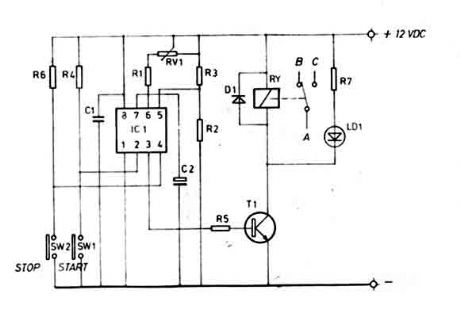
This timer is ideal for small aplications. Due to its simple structure, its usage and nevertheless its universal character, this mini timer is usable in the most current applications needing time intervals, from some seconds through approximately 60 minutes. By simple modifications it is possible to adjust the maximum time and the timing scale, as necessary. A strong output, made by a relay, permits to adapt, on the input and the output, whatever apparatus. (View)
View full Circuit Diagram | Comments | Reading(4113)
Open-phase protection circuit using three current transformers
Published:2012/9/12 2:14:00 Author:Ecco | Keyword: Open-phase protection , three current transformers
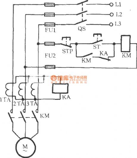
As shown in figure, 1TA, 2TA and3TAin circuit are three current transformers, andtheir secondary circuit are connetcedin parallel, then the loop is connected to a current relay KA. Duringthe motor M is in normal operation, KA does not operate. When there is a phase failure, zero-sequence current is approximately 1.73 times ofthe rated current, then KA acts tocut off the power for motor.
(View)
View full Circuit Diagram | Comments | Reading(2890)
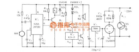
Voice-activated music outlet circuit using NJM2072D
Published:2012/9/12 2:16:00 Author:Ecco | Keyword: Voice-activated , music outlet

Asshown in the figure,the circuitusesvoice-activated ASICNJM2072D as the core component,butthe on-off ofoutletXS1 is controlled by TRIAC, and vocal circuit uses imitating animal soundIC KD- 56020 which is triggered bynegative level.
(View)
View full Circuit Diagram | Comments | Reading(1094)
Voice-activated music outlet circuit 1 using NJM2072D
Published:2012/9/12 2:26:00 Author:Ecco | Keyword: Voice-activated , music outlet

As shown in the diagram, the circuit consists of acoustic sensor, voice integrated circuit, relay control circuit, songs sound circuit and AC buck rectifier circuit and other components, and it can be used for the voice control automatic lights, voice control musical fountain, voice control barricades indicator and voice-activated automatic doors. ICl use voice control ASIC NJM2072D which is the core of the circuit device, and its internal functional block diagram is shown in the following figure.
(View)
View full Circuit Diagram | Comments | Reading(2009)
Voice-activated music outlet circuit 2 using NJM2072D
Published:2012/9/11 22:26:00 Author:Ecco | Keyword: Voice-activated, music outlet
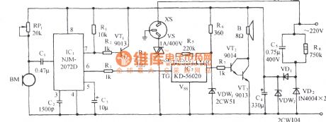
Asshown in the figure, it usesvoice-activated ASICNJM2072D as the core component,butthe on-off ofoutletXS1 is controlled by TRIAC, and vocal circuit uses imitating animal soundIC KD- 56020 which is triggered bynegative level.
(View)
View full Circuit Diagram | Comments | Reading(919)
Voice-activated music outlet circuit using SK-Ⅱ
Published:2012/9/12 2:28:00 Author:Ecco | Keyword: Voice-activated , music outlet
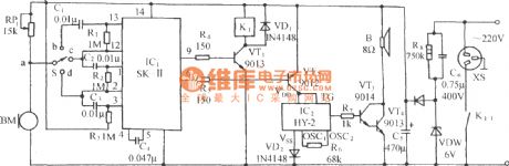
Asshown in the figure,the circuitincludes acoustic sensor , SK - II sound control circuit, relay control circuit, music sound circuit and AC buck rectifier circuit. BM is the acoustical / electrical transducer.
(View)
View full Circuit Diagram | Comments | Reading(681)
Voice-activated music outlet circuit using SL518
Published:2012/9/11 22:10:00 Author:Ecco | Keyword: Voice-activated, music outlet
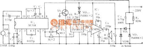
Asshown in the figure, it usesvoice-activated ASICSL518 as the core component. SL518is animproved product on the basis of SL517 withfewer external components, and its output isemitteroutput with stronger drive ability.
(View)
View full Circuit Diagram | Comments | Reading(811)
| Pages:60/312 At 204142434445464748495051525354555657585960Under 20 |
Circuit Categories
power supply circuit
Amplifier Circuit
Basic Circuit
LED and Light Circuit
Sensor Circuit
Signal Processing
Electrical Equipment Circuit
Control Circuit
Remote Control Circuit
A/D-D/A Converter Circuit
Audio Circuit
Measuring and Test Circuit
Communication Circuit
Computer-Related Circuit
555 Circuit
Automotive Circuit
Repairing Circuit