
Measuring and Test Circuit
Index 45
CAVE_MAPPING_TRANSMITTER
Published:2009/7/17 4:37:00 Author:Jessie
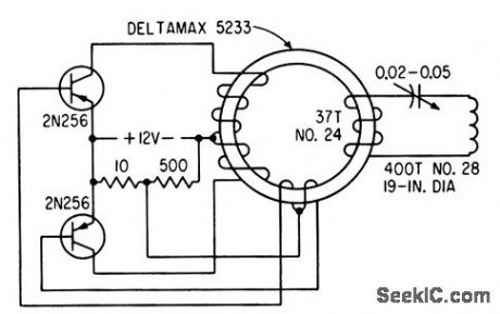
Transistorized 5-w, 2,000-cps generator of low-frequency magnetic induction fold direction finder feeds tuned loop in cave being mapped. Detector at surface locates vertical flux line over cave and also receives Morse code for communication.-E. R. Roesehlein, Mapping Caves Magnetically, Electronics, 33:39, p 61. (View)
View full Circuit Diagram | Comments | Reading(2752)
LANGMUIR_ELECTRON_DENSITY_PROBE
Published:2009/7/17 4:36:00 Author:Jessie
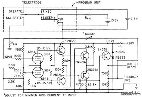
Used in Aerobee sounding rocket to measure day time sporadic-E ionization of upper atmosphere. Electrometer uses 100% feedback and Thyrite resistor to produce compressed scale on telemetry record.-M. F. Wolff, Rockets Probe Sporadic-E, Electronics, 35:211, p 18-19. (View)
View full Circuit Diagram | Comments | Reading(750)
WIND_CHILL_METER
Published:2009/7/10 21:38:00 Author:May
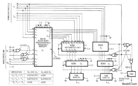
Circuit measures and displays wind-chill equivalent temperature by combining air temperature and wind speed data. PROM is programmed to act in combination with arithmetic-logic units to generate output values corresponding to those of wind-chill temperature chart adopted by National Weather Service. Article gives Iisting of PR0M contents.-V. R. Clark, PROM Converts Weather Data for Wind-Chill Index Display, Electronics, Jan. 5, 1978, p 158-159. (View)
View full Circuit Diagram | Comments | Reading(1152)
ALPHA_CUTOFF
Published:2009/7/17 4:31:00 Author:Jessie
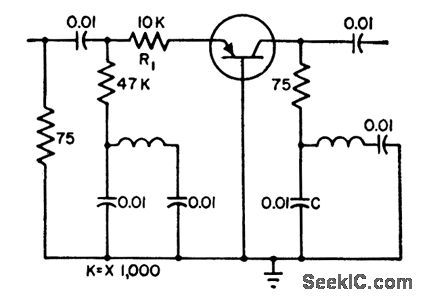
Measured with 3% accuracy up to 30 Mc and 5% up to 100Mc.Method compares transistor to short-circuit.-G. I. Turner, Measuring Transistor Alpha Cutoff, Electronics, 32:1, p 54. (View)
View full Circuit Diagram | Comments | Reading(1137)
HOT_COLD_METER
Published:2009/7/10 21:33:00 Author:May
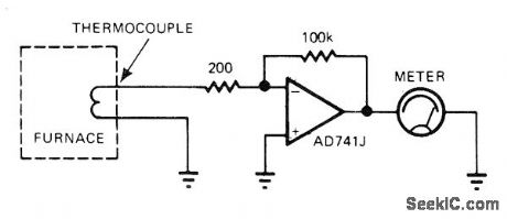
Output of unreferenced thermocouple dfives meter through opamp that provides required gain, for monitoring temperature inside furnace when exact temperature value is not required. Meter is simply calibrated in terms of hot and cold.-J. Williams, Designer's Guide to: Temperature Measurement, EDN Magazine, May 20, 1977, p 71-77. (View)
View full Circuit Diagram | Comments | Reading(1158)
MEASURING_NEGATIVE_RESISTANCE_OR_TD
Published:2009/7/17 4:30:00 Author:Jessie
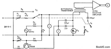
Thermistor cancels negative resistance of tunnel diode, and calibrated potentiometer that matches thermistor gives absolute value of td resistance at operating point. Q1 pro vides thermistor heating current, at level set by R6, while 5-v, 20-kc source provides ac to modulate bias of tunnel diode.-A.Ambrozy, Thermistor Measures Negative Resistance of Tunnel Diode, Electronics, 39:17, p 95-96.
(View)
View full Circuit Diagram | Comments | Reading(847)
COMPUTERIZED_METER
Published:2009/7/10 21:30:00 Author:May
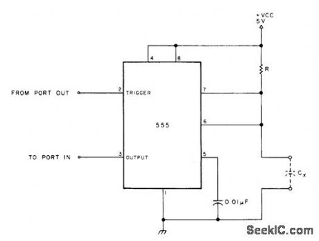
With 4.7 megohms for R, simple 555 timer circuit used in conjunction with computer measures capacitors in five ranges from below 100 pF to 0.1 μF. For larger range, resistor value can be changed. Article includes BASIC software suitable for 8080.based FROM PORT our systems, including calibration program based on known values of capacitance. 555 mono MVBR is triggered under control of computer output port bit, with count being made while mono is timing out. Count is averaged over ten triggerings, then multiplied in computer by calibration factor to give capacitance value. Any desired type of output indicator can be used.-J. Eccleston, Computerized Capacity Meter, 73 Magazine, July 1978, p 88-89. (View)
View full Circuit Diagram | Comments | Reading(891)
PLL_CAPACITANCE_METER
Published:2009/7/10 21:22:00 Author:May
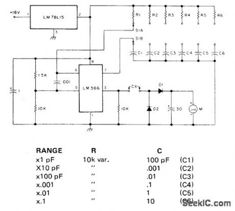
Based on fact thatalternating cument floating through capacitordepends on applied voltage, frequency,and capacitance value Circuit uses square wave forcharging capacitor to full voltage,then measures current flow as linear function of capacitance,LM78L15 provides regulated 15 V for LM566 PLL VCO. Frequency ofVCO depends on values of R and C selected by rotary switch S1,to give six linear scales:0-10 pF.10-100 pF.100-1000 pF,1000 pF to 0.01 μF,0.01-0.1μF and 0.1-1 μF Accuracy is about±5% Meter is 100 μA.Use small signal diodes,-S.Shields,How Many pF is That Capacitor,Really?, 73 Mgazine, March 1978,p 48-50.
(View)
View full Circuit Diagram | Comments | Reading(1783)
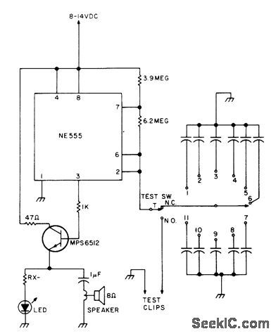
LINEAR_SCALE
Published:2009/7/10 21:11:00 Author:May
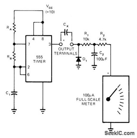
Wide frequency range and high output current of 555 timer contribute to linearity of operation as capacitance meter.Timer is connected as astable MVBR with frequency determined by values used for RA, RB, and C1. When timer output is high, unknown capacitance C1, is charged almost to VCC. When timer goes low, Cx discharges through D1. Use 100 kHz for 100-pF full-scale reading, 10kHz for 1 nF, 1 kHz for 10 nF, and down to 1 Hz for 10μF. Use regulated supply.-R. Horton, 555 Timer Makes Simple Capacitance Meter, EDN Magazine, Nov. 5, 1973, p 81. (View)
View full Circuit Diagram | Comments | Reading(6950)
MONO_AUDIO_LEVEL_METER
Published:2009/7/10 21:08:00 Author:May

This mono indicator uses both halves of a Samsung KAA2283.Levels displayes are -18 to 0dB in 2-dB steps. Sensitivity is 0.1 to 0.9mV. (View)
View full Circuit Diagram | Comments | Reading(941)
STEREO_AUDIO_LEVEL_METER
Published:2009/7/10 21:07:00 Author:May
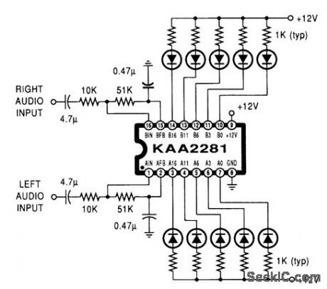
A Samsung KAA2281 and a few LEDs make up a simple stereo indicator. Levels displayed are -16, -11, -6, -3, and 0 dB. Input sensitivity is 1mV. LEDs can be any suitable types or a bar-graph display. (View)
View full Circuit Diagram | Comments | Reading(1911)
3_1_2_digit_LCD_DPM_DVM_using_the_8052_7101_A_D_pair_
Published:2009/7/19 20:46:00 Author:Jessie

31/2-digit LCD DPM/DVM using the 8052/7101 A/D pair (courtesy Intersell, Inc.). (View)
View full Circuit Diagram | Comments | Reading(2060)
Flowmeter_circuit_for_measuring_the_flow_rate_of_liquids_flowing_at_slow_speeds
Published:2009/7/19 20:42:00 Author:Jessie
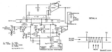
Flowmeter circuit for measuring the flow rate of liquids flowing at slow speeds. To understand the principle of operation refer to Detail A. T1 and T2 are temperature sensors. With no flow through the pipe power is dissipated into the medium symmetrically and there is no difference in temperature at T1 and T2. As flow begins T1 will take on the temperature upstream, but T2 will be influenced by the power dissipated into the moving stream. The time response of the flowmeter is in the order of 10 to 15 seconds (courtesy Analog Devices, Inc.). (View)
View full Circuit Diagram | Comments | Reading(1618)
Component_sorter_of_resistors_capacitors_and_zeners
Published:2009/7/19 20:40:00 Author:Jessie
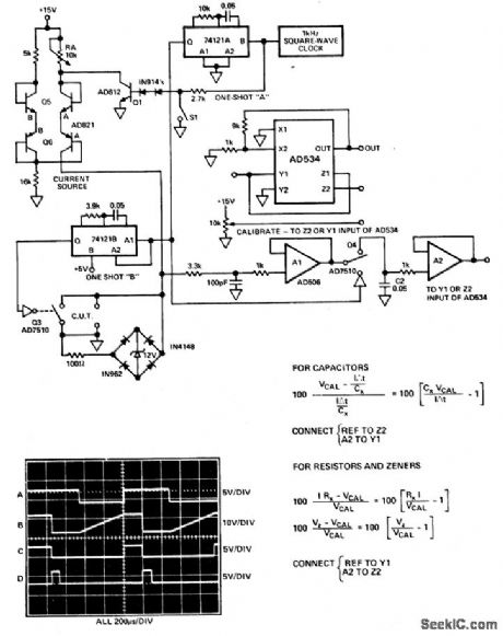
Component sorter of resistors, capacitors, and zeners. Trace A is a 1 kHz square-wave clock that is applied to Q1. The component under test (CUT) in this case is a 0.01 μF capacitor. It is allowed to charge until the clock goes high, turning of the current source (trace B). The voltage the capacitor sits at is inversely proportional to its absolute value. The AD506 follows this potential and feeds the sample-and-hold circuit Q4-C2-A2. The sample-and-hold circuit is enabled by one-shot A for 200 μs when the clock goes high (trace C). After this time one-shot A goes low triggering one-shot B on for 100 μs. This pulse drives Q3 on (trace D) and discharges the CUT. This same fixture can check resistors and zeners by closing S1. This allows the current source to run all of the time. This is necessary since resistors and zeners have no memory (courtesy Analog Devices, Inc.). (View)
View full Circuit Diagram | Comments | Reading(987)
Peak_to_peak_noise_measuring_circuit_for_frequencies_between_01_hertz_and_10_hertz
Published:2009/7/19 20:33:00 Author:Jessie
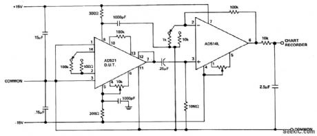
Peak-to-peak noise measuring circuit for frequencies between 0.1 hertz and 10 hertz. Typical measurements are made by reading the maximum peak-to-peak voltage noise of the device under test (DUT) for three periods for 10 seconds each (courtesy Analog Devices, Inc.). (View)
View full Circuit Diagram | Comments | Reading(1218)
Precision_analog_tachometer_using_an_MC14538B
Published:2009/7/19 20:32:00 Author:Jessie
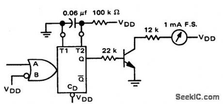
Precision analog tachometer using an MC14538B. The MC14538B operates as a monostable multivibrator with an output pulse of 6 ms. This pulse drives the transistor which in turn drives the meter. Full-scale calibration should be made at 167 hertz, which corresponds to 10,020 RPM (courtesy Motorola Semiconductor Products Inc.). (View)
View full Circuit Diagram | Comments | Reading(1309)
SOUND_LEVEL_METER_1
Published:2009/7/10 20:50:00 Author:May
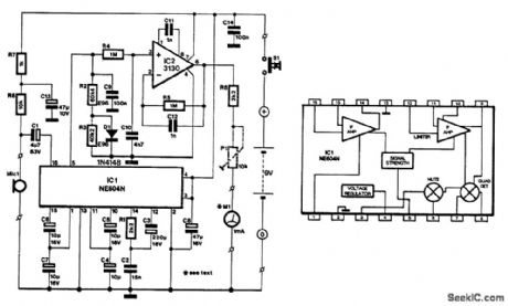
The NE604's signal-strength indicator section is used, based on an internal logarithmic converter.This enables a linear decibel scale so that the moving-coil meter (shown in the diagram) can be replaced by a digital instrument.
The signal source is assumed to be an electret microphone that converts ambient noise into an electri-cal signal. Because this type of microphone normally contains a buffer stage, R7, R8, and C13 have been included to provide the supply voltage for this stage.
The NE604 delivers an output current (at pin 5) of 0 to 50 μA, which causes a potential difference across R2+R3 of 0 to 5V. The input and output signal range is equivalent to a sound range of 70 dB. To compensate for the effects of temperature changes, the required resistance of 100 kΩ is formed by two resistors (R2 and R3) and a diode (D1).
Any ripple remaining on the output voltage is removed by R4/C9/C10 before the output is buffered by IC2. The indicating instrument, here a moving-coil meter, is connected to the output (pin 6) of IC2 via a series resistance, R6+P1. The preset is adjusted to give full-scale deflection (FSD) for an output voltage of 4V.
Calibrating the meter is a little tricky, unless you have access to an already calibrated instrument. Oth-erwise, if you know the efficiency of your loudspeaker, that is, how many decibels for 1W at 1m, you can use that as reference. The scale of the meter can then be marked with the (approximate) value. In any case, the meter deflection must at all times be seen as an indication, not as an absolute value: it was not thought to be worthwhile to add a filter to the circuit to enable absolute measurements to be made.
(View)
View full Circuit Diagram | Comments | Reading(2334)
High_precision_tachometer
Published:2009/7/19 20:32:00 Author:Jessie
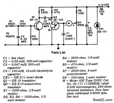
High-precision tachometer. Capacitor C1 is rated at 200 volts. The meter shown is a standard panel meter with a 0 to 500 μA range. It is available from GE with a modified faceplate. For information about the modified meter write to General Electric Company, Tube Dept., Attention R.G. Kempton, 316 East Ninth St., Owenboro, KY 42301. R7 is used to calibrate the tachometer before it is installed. Feed a 60-hertz signal to the input (to point). On four stroke engines with four cylinders adjust for 1800 RPM, with six cylinders adjust for 1200 RPM and with eight cylinders adjust for 900 RPM. On two stroke engines with three cylinders adjust for 1200 RPM and with four cylinders adjust for 900 RPM. The 60-hertz signal should be no greater than 9 volts AC (courtesy General Electric Company). (View)
View full Circuit Diagram | Comments | Reading(956)
Ratiometric_measurement_circuit_using_an_ADC171_dual_slope_integrating_
Published:2009/7/19 20:30:00 Author:Jessie
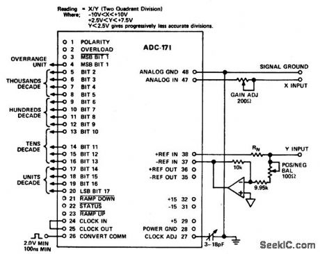
Ratiometric measurement circuit using an ADC171 dual-slope integrating A/D converter (courtesy Analog Devices, Inc.). (View)
View full Circuit Diagram | Comments | Reading(696)
Decibel_measurement_circuit_using_an_AD536_true_RMS_to_DC_converter_chip
Published:2009/7/19 20:29:00 Author:Jessie
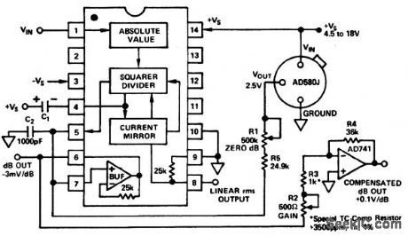
Decibel measurement circuit using an AD536 true RMS-to DC converter chip (courtesy Analog Devices, Inc.). (View)
View full Circuit Diagram | Comments | Reading(1728)
| Pages:45/101 At 204142434445464748495051525354555657585960Under 20 |
Circuit Categories
power supply circuit
Amplifier Circuit
Basic Circuit
LED and Light Circuit
Sensor Circuit
Signal Processing
Electrical Equipment Circuit
Control Circuit
Remote Control Circuit
A/D-D/A Converter Circuit
Audio Circuit
Measuring and Test Circuit
Communication Circuit
Computer-Related Circuit
555 Circuit
Automotive Circuit
Repairing Circuit