
Measuring and Test Circuit
Index 52
WATER_LEVEL_MEASUREMENT_CIRCUIT
Published:2009/7/9 3:18:00 Author:May


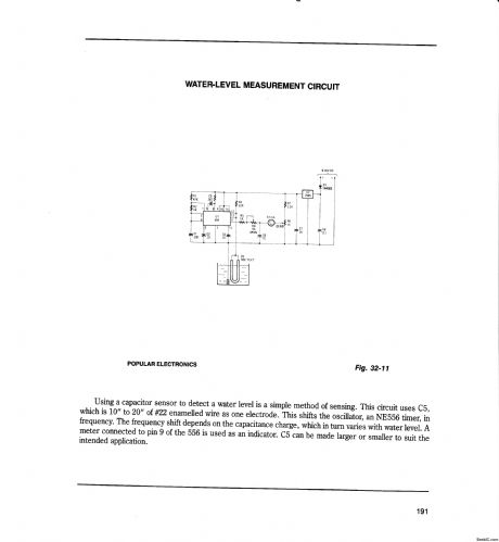


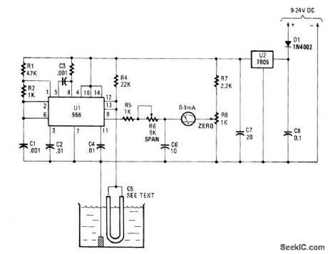
Using a capacttor sensor to detect a water level is a simple method of sensmg.This circuit uses C5,which is 10 to 20 of ﹟22 enamelled wlre as one electrode,This shifts the oscillator, an NE556 timer, infrequency..The frequency shift depends on the capacitance charge,which In turn vanes with water level.Ameter connected to pin 9 of the 556 is used as an indicator. C5 can be made larger or smaller to suit the intended application. (View)
View full Circuit Diagram | Comments | Reading(2890)
FULL_CUP_DETECTOR_FOR_THE_BLIND
Published:2009/7/9 3:03:00 Author:May
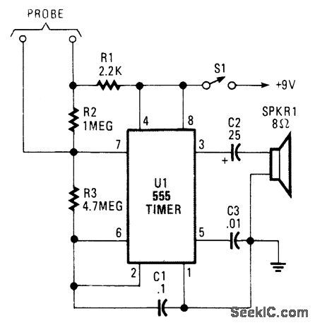
At the heart of the Full-Cup Detector is a 555-oscillator/timer conftgured to produce a 15-Hz click, until its probe contacts are bridged, at which time its output frequency goes to about 500 Hz.
This circuit can be used by the visually handicapped to determine when a cup or bowl is full of liquid (coffee, soup, etc). U1, an NE555, produces ticks at 15 Hz. A set of probes (wire, etc.) is placed in the container at the desired level. When the liquid level contacts the probes, the frequency of clicks increases to several hundred hertz, depending on its conductivity. (View)
View full Circuit Diagram | Comments | Reading(1070)
MOISTURE_DETECTOR
Published:2009/7/9 2:54:00 Author:May
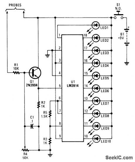
A bar-graph LED driver is used to drive 10 LEDs to give a relative indication of moisture. The mois-ture probes are connected so that electrical conductivity due to moisture tends to forward bias Q1, provid-ing a dc voltage at pin 5 of U1 that is proportional to leakage current. Ideally, the probes should be made of stainless steel. (View)
View full Circuit Diagram | Comments | Reading(0)
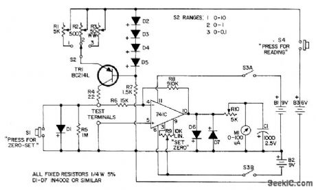
LINEAR_OHMS_MULTIMETER
Published:2009/7/20 20:36:00 Author:Jessie
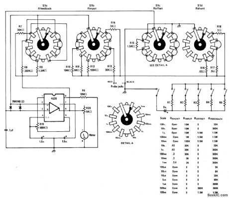
Full-scale value for each of five resistance ranges is determined by values used for R1-R5. Table gives values of resistors connected to each layer of three-gang 12-position selector switch to obtain five volt-age ranges and 12 current ranges for other multimeter functions. For dual multimeter, duplicate circuit for other section to permit measuring input and output signals simultaneously.-J. Sandier, ME's New Twin Electronic Multimeter, Modern Electronics, Oct.1978, p 58-61. (View)
View full Circuit Diagram | Comments | Reading(3202)
CONTINUITY_CHECKER
Published:2009/7/20 20:35:00 Author:Jessie
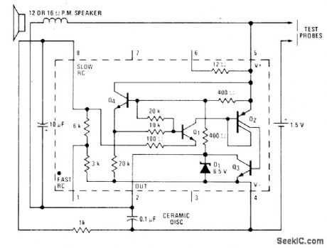
National LM3909 IC operating from 1.5-V cell provides enough audio power to drive loudspeaker when probes are shorted by resistance up to about 100 ohms. By probing two points in rapid succession, small differences in resistance can be detected by noticeable differences in tone; this feature is useful for identifying windings of transformers.- Linear Applications, Vol. 2, National Semiconductor, Santa Clara, CA, 1976, AN-154, p 4-5. (View)
View full Circuit Diagram | Comments | Reading(0)
AC_OHMMETER
Published:2009/7/20 20:33:00 Author:Jessie
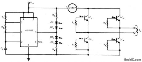
Optoisolator circuit operating from single battery develops alternating current for measuring resistance of soils and construction materials without errors due to polarization and earth-current effects. 555 IC timer controls output at frequency determined by R1, R2, and CT, R1 is made very much less than R2 but should not be below about 1 K. Frequency value is 1.44/(R1 + 2R2)CT Output switching matrix is controlled by timer so OC1 and OC4 are on for one half-cycle and OC2 and OC3, are on for other half. Output current is independent of frequency and duty cycle up to 150 Hz. With Monsanto MCT-2 optoisolators, R3 and R4, are 330 ohms and R5-R8 are each 22K.-D. J. Beckwitt, AC Ohmmeter Provides Novel Use for Opto-Isolators, EDN Magazine, July 5, 1974, p 70. (View)
View full Circuit Diagram | Comments | Reading(1129)
TWO_TRANSISTOR_CARDIAC_PACEMAKER
Published:2009/7/20 20:33:00 Author:Jessie
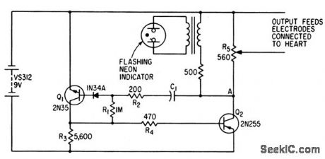
Produces triggering pulses that stimulate heartbeats during surgery. Repetition rate is determined by C1 and R1. Pulse duration is 4 millisec, with 8-V peak that sends 16 ma through 500-ohm load.-W. E. Gilson and H. F. Klinge, Cardiac Pacemaker Triggers Heartbeats, Electronics, 34;40, p 80. (View)
View full Circuit Diagram | Comments | Reading(4632)
LOW_VOLTAGE_OHMMETER
Published:2009/7/20 20:31:00 Author:Jessie
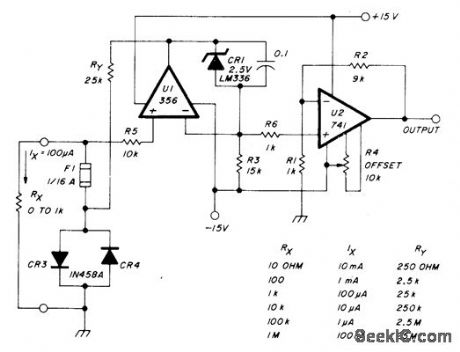
Combines stable constant-current source U1-CR1-RY with DC amplifier U2 having gain of 10 to keep applied voltage down to 0.1V. Output is linearly proportional to unknown resistance. Resistances well below 1 ohm can be measured accurately, U2 scales 0-100 mV unknown voltage to 0-1 V at output, so 1K resistor under test can be read as 1.000K on DVM scale. U2 should be offset-nulled to eliminate zero error, for best low-scale accuracy, by shorting input and adjusting R4 for 0.000 V out of U2. Full-scale calibration involves trimming individual range values ofRY for correct output, while using reference value for RX. Fuse and clamp diodes protect range resistors, and R5 protects opamp.-W. Jung, An IC Op Amp Update, Ham Radio, March 1978, p 62-69. (View)
View full Circuit Diagram | Comments | Reading(1271)
RLC_BRIDGE
Published:2009/7/20 20:29:00 Author:Jessie
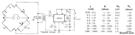
Maxwell bridge uses only one re-active element for measuring resistance, inductance, and capacitance. Wagner ground balances stray internal capacitances to ground to obtain perfect null. Measurement ranges are shown in table. 0ver fixed range, RA can be calibrated to read inductance values directly. RA and RB can be calibrated initially over their variable ranges by using standard resistors. Measurements are not affected by frequency of driving source. Circuit is set up as shown for measuring inductance. If standard inductance is used in place of Lx, unknown capacitor at CB can be measured. Signetics NE555 is connected as astable oscillator running at about 1000 Hz with values shown for R and C, drawing 6.5 mA from 9-V battery. Article covers construction and calibration and gives balance equations for all measurements.-J. Ii. Ellison, Universal L, C, R Bridge, Ham Radio, April 1976, p 54-55. (View)
View full Circuit Diagram | Comments | Reading(3834)
3_V_WATER_LEVEL_DETECTOR
Published:2009/7/9 2:31:00 Author:May
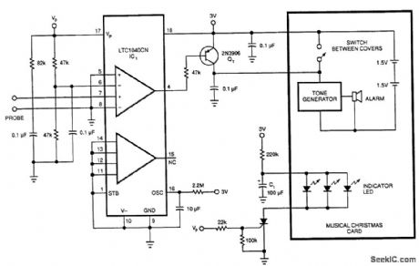
Originally, this circuit was used to sense a low-water level in a Christmas tree stand, but the circuit can be used as a water-level detector for pump controls, water sensors (for garden and lawn applications), etc.A comparator and probe setup with a Linear Technology LTC1040CN comparator drives a 2N3906, which switches a tone generator. Sampling occurs every 20 seconds, which minimizes current drain. A pair of dry cells will power the circuit for several months. (View)
View full Circuit Diagram | Comments | Reading(1224)
FET_VOM
Published:2009/7/20 20:17:00 Author:Jessie
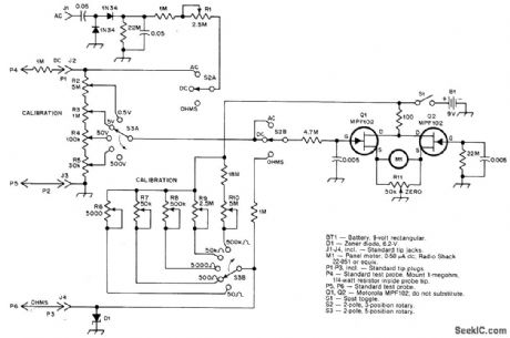
Use two FETs in balanced circuit. Meter reads zero when circuit is balanced with R11. Values being measured produce imbalance linearly proportional to output voltage of bridge. Resistance measurements use linear ohms-readout system, with single meter scale serving for all resistance and voltage measurements. In ohms position, meter will rest gently against peg at high end of scale. When ohmmeter leads are shorted, zero pot is adjusted so meter reads 0 ohms. Article covers construction and calibration.-J. Rusgrove, An FET Volt-Ohmmeter with Linear Ohms Readout, QST, March 1978, p 16-18. (View)
View full Circuit Diagram | Comments | Reading(3407)
THREE_RANGE_MILLIOHMM_ETER
Published:2009/7/20 20:16:00 Author:Jessie
Solid-state design measures resistance values accurately down to less than 0.001 ohm. Full-scale values for ranges are 10, 1, and 0.1 ohms.-Circuits, 73 Magazine, July 1974, p 80. (View)
View full Circuit Diagram | Comments | Reading(1452)
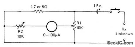
LINEAR_SCALE_OHMMETER
Published:2009/7/20 20:14:00 Author:Jessie
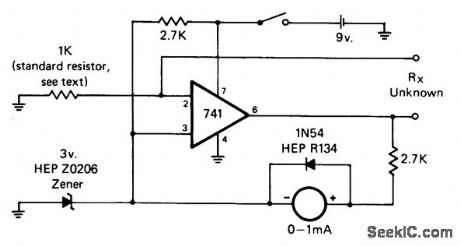
Unknown resistance value is arithmetic product of standard resistor value and current reading in milliam-peres. With 1K standard resistor, deflections from 0 to 1 A correspond to resistance readings from 0 to 1K. Requires no calibration and no zero adjustment. Can be made multirange by switching in different standard resistors.-J.Schultz, An Ohmmeter Potpourri, CQ, June 1978, p 32-33. (View)
View full Circuit Diagram | Comments | Reading(0)
WATER_SEEPAGE_ALARM
Published:2009/7/20 20:12:00 Author:Jessie
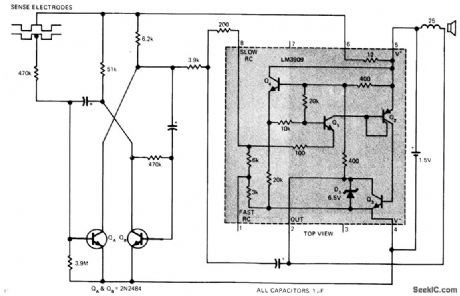
National LM3909 flasher IC operating from 1.5-V cell provides safe water-seepage alarm for potentially damp floors because there is no connection to power line, When sensing electrodes pass about 0.25μA through moisture, pair of 2N2484 transistors (QA and QB) become astable MVBR operating at rate that starts at 1 Hz and increases with leakage between electrodes. Pulse waveform applied to pin 8 of IC varies timing current of flasher, resulting in distinctively modulated tone output for loudspeaker of alarm. Sensors can be two strips of stainless steel on insulators or zigzag path in copper of printed-wiring board. Place damp finger across gap to test alarm.-P. Lefferts, Power-Miser Flasher IC Has Many Novel Applications, EDN Magazine, March 20, 1976, p 59-66. (View)
View full Circuit Diagram | Comments | Reading(0)
AUDIBLE_OHMMETER_1
Published:2009/7/20 20:11:00 Author:Jessie
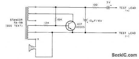
Volume and/or pitch of one-transistor audio oscillator varies with resistance across test terminals, to give audible indication of continuity and relative resistance without looking at meter. Can also be used as transistor and diode tester, signal injector, code practice oscillator, and CW monitor. Oscillator uses transistor-type transformer having center tapped windings, connected as shown to give three-winding transformer. Operates from two 1.5-V cells in series. Will respond to resistance values from short to about 100K. Volume in-creases and pitch rises as resistance is increased. For very low resistance, tone resembles croaking of frog.-Build the EI Sapo Tester, 73 Magazine, Dec. 1977, p 184-185. (View)
View full Circuit Diagram | Comments | Reading(1088)
MOISTURE_TESTER
Published:2009/7/20 20:06:00 Author:Jessie
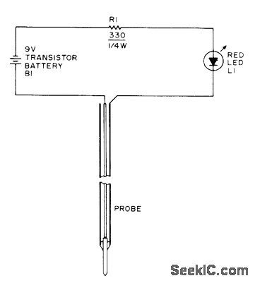
Simple probe tells when plants need watering. Amount of moisture and minerals in soil together determine current available for LED. Almost full brilliance indicates adequate moisture, and no illumination means plant needs water badly. Probe can be No. 14 wire filed to point and centered with epoxy in 3/16-inch copper tubing, or simply two stiff probe wires about 1 inch apart.-W. L. MacDowell, The Violet Tester, 73 Magazine, May 1975, p 52-53. (View)
View full Circuit Diagram | Comments | Reading(853)
BRIDGE_FOR_01_5_OHMS
Published:2009/7/20 20:05:00 Author:Jessie
Set meter reading to zero with multiturn pot R1 when test leads are shorted. Simple one-point calibration is made by using known low resistance for about midrange value and setting meter to convenient scale marking by adjusting R2. Calibration curve is then made for meter scale by using other normal resistances.-J. Schultz, An Ohmmeter Potpourri, CQ, June 1978, p 32-33. (View)
View full Circuit Diagram | Comments | Reading(835)
500_MEGOHM_LINEAR_SCALE_OHMMETER
Published:2009/7/20 19:59:00 Author:Jessie

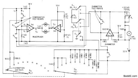
Resistance multiplier using 741 opamp reduces current drain when measuring low resistance values(below 10 ohms), LEDs indicate voltage difference between outputs of A1 and A2. as guide for minimizing difference during measurement. RS sets meter for full-scale deflection when measuring resistor value equal to standard RC.-E.H. Armanino, Extending the Range of the Linear-Scale Ohmmeter,Electronics.Dec.22.1977,p93-94. (View)
View full Circuit Diagram | Comments | Reading(2760)
AUDIBLE_OHMMETER
Published:2009/7/20 19:59:00 Author:Jessie
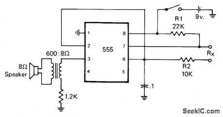
Circuit is built around 555 timer. Resistance detection range is from 0 ohms to about 10 megohms. At high end of range, output is series of clicks from loudspeaker, and at low end is high-pitched tone. Intermediate resistance values produce different tones. Current through unknown resistance is only a few microamperes, so semiconductor junctions can be checked without damage. R2 80 sets frequency for 0 ohms. Can also be used as Speaker code practice oscillator if RX terminals are shorted and ground lead of pin 1 is keyed.-J.Schultz, An Ohmmeter Potpourri, CQ, June 1978, p 32-33. (View)
View full Circuit Diagram | Comments | Reading(1006)
PHASE_DETECTOR
Published:2009/7/9 2:15:00 Author:May

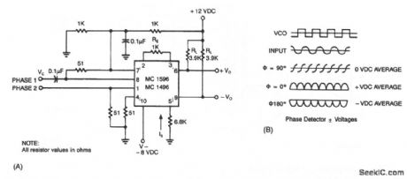
The output of the detector contains a term related to the cosine of the phase angle. Two signals of equal frequency are applied to the inputs. The frequencies are multiplied together, producing the sum and difference frequencies. Equal frequencies cause the difference component to become dc, while the undesired sum component is ftltered out. The dc component is related to the phase angle by the graph of Fig.70-2B. At 90°, the cosine becomes zero, while being at maximum positive or maximum negative at 0°and 180°, respectively. The advantage of using the balanced modulator over other types of phase comparators is the excellent conversion linearity. This configuration also provides a conversion gain, rather than a loss for greater resolution. Used in conjunction with a phase-locked loop, for instance, the balanced modulator provides a very low-distortion FM demodulator.
Correct phase sequences (ABC, BCA, or CAB) produce trains of output pulses and illuminate the LED. The output stays low and the LED remains dark for incorrect sequences (BAC, ACB, or CBA) or for phase loss (phase A, B, or C missing). (View)
View full Circuit Diagram | Comments | Reading(2144)
| Pages:52/101 At 204142434445464748495051525354555657585960Under 20 |
Circuit Categories
power supply circuit
Amplifier Circuit
Basic Circuit
LED and Light Circuit
Sensor Circuit
Signal Processing
Electrical Equipment Circuit
Control Circuit
Remote Control Circuit
A/D-D/A Converter Circuit
Audio Circuit
Measuring and Test Circuit
Communication Circuit
Computer-Related Circuit
555 Circuit
Automotive Circuit
Repairing Circuit